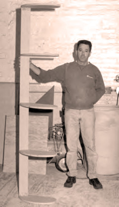
In January 2001, the first audioXPress magazine issue (Vol. 32 No.1) included a project from Thomas Perazella, highlighted in its cover, which has been considered by many one of the best DIY high-end speaker projects ever published in the publication’s history. Titled “On Angel’s Wings” and published in two parts (the second part appeared in the following issue) the articles described in detail the design and construction of a speaker using the Bohlender Graebener RD-75 planar magnetic driver, including references to previous experiments with dipole baffles. Tom’s project aimed to achieve the best of both worlds, maximizing the spacious sound of the BG RD-75 planar magnetic drivers with the dynamic range of conventional drivers, which would require a carefully designed speaker in a dipole configuration. This is the first part of the project that audioXpress is now making available online.
On Angel’s Wings, Part 1
You’ve all probably had the sensation of something visual or audible literally grabbing your attention because the effect it produces in your mind is so striking. I remember that happening to me the first time I heard an electrostatic speaker. Nothing before had ever sounded so utterly detailed or spacious. I was hooked. The sound was so glorious that it blanked out the fact that the frequency response and dynamic range of the sound was limited.
Over time, after listening to a broad range of source material, those shortcomings became all too apparent. My dynamic speakers were capable of reproducing a better physical sense of the performance, although the romance was missing. The desire persisted to have the detailed sound that electrostatics and planar magnetics can produce. I kept asking myself why there were no speakers that could produce this detail while also having the frequency range of classical dynamic speakers.
The Bohlender Driver
Enter, stage left, the Bohlender Graebener RD-75 driver. It happened while I was in Boston on a business trip. I stopped in to visit a member of the Boston Audio Society with whom I had been discussing subwoofers. As I walked into his listening room, I saw these large, thin drivers standing next to his huge subs. They were mounted in baffles and operated in dipole fashion. Hmmm, I thought. This could be interesting. I asked him what they were, and he proceeded to explain that they were planar magnetics manufactured by a company called Bohlender Graebener (BG).
As soon as the music started, it all became clear. Here were drivers that had the best of both worlds. Detail and spaciousness were wed with dynamic range. And what a marriage it was. I was hooked again. To top it off, I’m a real sucker for dipoles, and here was a pair of dipoles that could rock. I knew that things were about to change for me.
Shortly after that, one of the Prairie State Audio Construction Society meetings was held at the home of a member who had a pair of RD-75s in a monopole configuration. Although the sound was different, it was a case of same church, different pew. The basic character of the driver was still wonderful. Attending that meeting was Audio-XStream’s Rudi Blondia, (at the time) the distributor of BG products to the DIY market, and also a very knowledgeable and helpful guy. To say that he believes in these drivers is an understatement. Rudi mentioned that he had a pair of RD-75s with a custom-designed baffle at his house not far from the Los Angeles airport, and that I should visit him if I were in the area.
Mounting Method
The question now was not whether RD-75s were going to be in my future, but only how. Being a dipole lover, the first part of the equation was easy. The configuration would be dipole. But how would I mount them? Would the baffle be flat, curved, symmetric, asymmetric, or what?
Back to Rudi, at Audio-XStream’s website, he provided not only a lot of information on the drivers, but also links to work done by John Whittaker and himself in 1997, testing various baffles with the RD-75 and other planars. Their results confirmed that the best response with the RD-75s was obtained by using curved, asymmetrical baffles, a configuration which reduces the tendency for these drivers to have a bump around 300Hz.
Visions of curved asymmetric baffles began floating around in my head. I needed to narrow the choices. As luck would have it, I was going to LA on business, so I called Rudy to arrange a visit. On my way back to the airport, I stopped by and heard his implementation of the baffle.
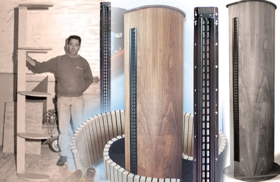
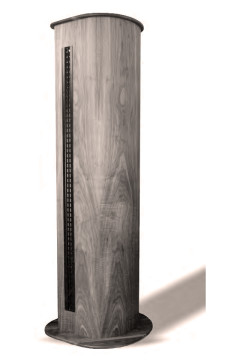
It sounded great. Then he showed me a new design that was still in prototype stage, using multiple curved sections of plywood. Based on Rudi’s prototype, I decided on a baffle with a very short distance from one side of the driver to a small-radius curve on one side. The other side of the driver would face a larger baffle made essentially from a 12″-radius curve mating with a 4″-radius curve and then returning to the back side on a straight line.
One of the most significant problems I faced was building a 7′-tall baffle in my basement. The low ceiling height, coupled with HVAC ducts, plumbing, and electrical conduits, would make it very difficult to move large sections without hitting anything. Then good fortune struck. I happened to mention the dilemma to my neighbor who is a building contractor, and he mentioned that he had a millworks in town where he produced custom cabinets for some of his jobs. He suggested I contact his manager to see if he could help.
Talk about manna from heaven! I went down to his shop and found that he not only had a large, well-equipped workspace, but that his manager, Dave Coombs, was willing to have me work there. Now I needed to become serious about putting my ideas on paper.
Airplane-Wing Shape
While making a scale drawing of the cross section of the baffle shape, it struck me that it resembled drawings I had done when building model-airplane wings. Could a speaker baffle be built like a model-airplane wing? Building a wing requires a series of ribs to determine its shape, one or more spars for structural strength, and an outer skin to direct the airflow. The advantage of this method is that you can achieve complex shapes by making a pattern for the ribs and then cutting them out of flat stock.
The process of creating the ribs and spars for the baffle was a simple transfer from the procedure of making a model airplane wing, although on a larger scale. The difficult part would be finding a suitable material for the rib covering. For an airplane wing, a thin but tough plastic material is stretched and sealed over the ribs and spars to keep the airflow (essentially a steady-state pressure) from passing through the wing.
That kind of material would not do for a speaker baffle, however, where the airflow is not steady-state, but a varying pressure. The electrical analogy is the difference between a DC and AC signal, where the wing coating behaves like a capacitor, blocking DC but passing AC. Using a wood veneer would not provide a smooth appearance or sufficient structural strength if applied directly to the ribs, and curved plywood sections would not do because of the difficulty of achieving a smooth joint between sections having different radii. I needed to find a new material.
Dave, after some checking with one of their suppliers, came up with two possible solutions. The first was a material called Timberflex, which consists of a 1/8”-thick sheet of birch plywood attached to a series of either 3/8” or 5/8” stringers spaced about 3/16” apart for the full length of the sheet. This results in a thickness of either 1/2” or 3/4”, depending on which version is used. The material is flexible in one direction, and relatively rigid in the other. At first it looked promising, but the manufacturer’s specs give 5” as the minimum radius, and the sample supplied seemed more comfortable with a 6″ radius. In either case, it was too stiff to work with the 4″ radius I planned to use.
The Kerfkore Decision
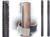
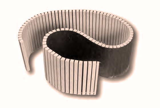
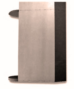
The second material, called Kerfkore, consists of 1/2” stringers separated by about 3/16” like the Timberflex, but attached to heavy black paper instead of plywood. This results in a much more flexible material that bends to a radius approaching 2″. It looked as though I had a winner (Photo 1).
I then produced a full-size drawing of the cross section of the baffle, detailing each piece. In constructing the baffle, I would use 3/4” MDF for the ribs, spar, and front driver-mounting plate, and 1/2” particleboard for the back plane. I would cover the ribs with Kerfkore, and form the baffle short-end radius with sections of 1 1/16” quarter-round, since no suitable half-round was available at the local lumber supply.

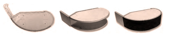
I formed these templates by cutting out the appropriate sections of the drawings, gluing them to a piece of 3/16” Luan board, and then cutting the board to match the drawing. In addition to providing an outline of the parts to be cut, these templates provided a way to ensure alignment of the mounting holes between the frame and top and bottom plates. Photo 2 shows one of the templates.
To prove the concept, I next produced a prototype consisting of most of the major pieces. It was made of two 3/4” MDF ribs, a 3/4” MDF spar, a 1/2” backplate (particleboard in this case, but it could as well have been MDF), a driver mounting plate made of 3/4” MDF, and a piece of Kerfkore to cover the ribs. The prototype did not have top or bottom sections or the short end radius, as these were relatively straightforward pieces.
Construction Starts
I then started to construct the actual pieces. One 4′ × 8′ sheet of 3/4” MDF was sufficient for all the MDF parts. The first step was to cut out ten rib sections. I ripped square pieces just large enough for the ribs from the MDF sheet, and drew the outline for each rib on those pieces, using the rib template. I used a band saw to make a rough cut of the rib shape, and finished the shaping with a large disc sander. The ribs had a smooth curve, terminating at one end in the flat section I glued to the spar, and at the other end in a recessed flat section to accept the flat back plate.
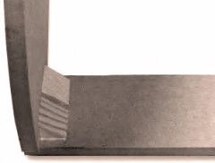
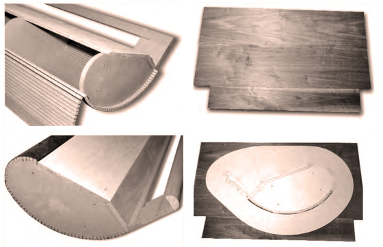
Using glue and a pneumatic nail gun, I then fastened the ribs to two spars ripped from the MDF sheet. For those of you who have not used a nail gun, you’re in for a real treat. Not only is the assembly a lot faster, but it’s a one-handed operation, leaving the other hand free to help maintain alignment during the process. Once the glue is dry, the resulting joint is very solid. To provide additional stability, I used corner blocks where the end ribs joined the spars (Photo 5).
Once I fastened all the ribs to the spar, I could visualize the structure of the baffle a little easier. Photo 6 is a view of a finished rib/spar assembly. To give you a sense of scale, Photo 7 shows Dave holding one of the rib assemblies. The next step was to cut and attach the back plates. I cut these pieces from 1/2” stock and rested them in the recesses of the ribs. This combination of plate thickness, recessing, and the thickness of the Kerfkore resulted in the plate being about 1/4” below the edge of the Kerfkore, a difference in height that allowed for the thickness of the carpet to be added later.
The plate joined the spar at an angle of 30°, so I needed to cut one edge of the plate at that angle. I then glued and nailed the plate into place (Photo 8). Once the back plate was secured, the whole rib assembly became quite rigid.
The only other parts made from MDF were the two driver mounting plates. At first I thought of cutting the plate as one piece and routing the opening, but because of the shape of the driver, that job would have been rather complicated. The openings
for the drivers are long and narrow, which would require setting up long guides to make sure the holes were straight. I would need to rout another groove along one edge to accept the Kerfkore sheet. In addition, some raised areas at the top and bottom of the drivers allow for the electrical connections, and the plate would need routing to provide clearance for those areas.
Dave listened to my plan, looked at the drawing and the driver, and said, “That looks too difficult. I think I know an easier way. Let’s build it up from individual straight pieces of MDF.” He promptly whipped out a pencil and drew four straight pieces of MDF. One was the side of the mount that had the recess for the Kerfkore. This was no problem to make: simply cut a straight piece on the table saw and then make two more passes on one edge with the saw blade and rip fence adjusted to the correct dimensions to produce the relief.
The second piece was the side of the mount away from the Kerfkore, and that was a simple straight cut. The last two pieces were the top and bottom sections, which were straight cuts with two additional passes to make the recesses for the raised connection areas of the drivers.

Once the mounting plates were dry, we glued and nailed them to the rib assemblies. The recessed edge of one side resulted in a flush mounting surface with the edge of the rib, allowing the Kerfkore to start at the mounting plate and smoothly transition to the ribs. The relationship of the ribs, spars, backplate, and mounting plate is shown in Photo 10. Photo 11 is another view of the assembly, with a clearer view of the relief groove in the mounting plate and the relationship to the rib.
Top And Bottom Plates
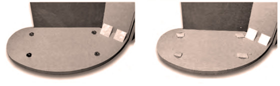
Before covering the ribs, we needed to provide for mounting the top and bottom plates. To fasten the plates to the top and bottom ribs, I inserted 1/4” × 20 T nuts into the ribs to accept corresponding bolts and screws. For connections to the mounting plate and end half round, I would use wood screws, with pilot holes drilled for them. Photo 12 shows the T nuts in place.
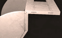
Photo 13 shows those retainers in place. Next came the moment of truth. Would I be able to get the full sheet of Kerfkore to work the way it did on the prototype? I measured and cut the sheet with about an inch of excess beyond the top and bottom ribs, placed it on the rib assembly, and checked it for fit. Then I applied glue to the mounting-plate recess and rib edges, and nailed the Kerfkore to the mounting plate and the leading edges of the ribs. Finally, I wrapped the balance of the Kerfkore and nailed all the way around. Photo 14 shows the operation in progress.
After allowing the glue to dry, I trimmed the excess Kerfkore using a router, which resulted in a nice flush edge for mounting the top and bottom plates. I built up a half-round edge from two quarter-round pieces and glued and nailed it to the other edge of the mounting plate. (Normally, I would have preferred to purchase the half round, but no suitable sizes were available locally.) I then drilled holes through the back plate on both sides of the rib cavities to allow for inserting sound-absorbing insulating foam at a later stage. Photo 15 shows the completed rib assembly.
I now needed to make a major decision before I could fashion the top and bottom plates. Up to this point, all the wood was generic, but since I wished to make the top and bottom plates of solid hardwood, the choice of wood and veneer type was at hand. I spent a lot of time looking at various rare woods, but the final decision required that the wood be available and fit with current other pieces of furniture in my home.
Having for a long time been a fan of walnut, I picked American walnut for its color, grain, and ability to fit with current pieces. However, finding local planks large enough for these plates proved to be impossible. Instead, I settled for some very nice pieces of 1″ planks in various widths and lengths out of which to build up larger pieces.
The following are points to consider when building pieces such as this. Use raw stock pieces that are complementary in color and grain, making sure the edges are very square, straight, and smooth. Reverse the grain patterns when viewed end on from grain up to grain down on adjacent pieces. Since good hardwood is quite expensive, you should avoid making square pieces if the shapes you desire are not square. Rather, leave only enough excess to make the assembly and cutting operations easy, with a minimum of waste.
I examined pieces of raw stock, cut them to length, and placed them next to each other to make sure all was OK. Then I made pencil marks across mating sections to assist in reassembling them properly, and ran them through a jointer until smooth and straight. I applied glue to the mating edges and clamps to hold them in place. I clamped them lightly at first, and used a hammer and wooden block to ensure all edges were flush with each other.
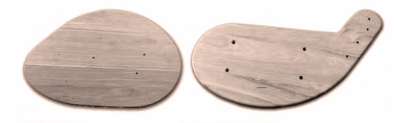
To cut the base and top pieces, I used templates, making the original drawings on Luan board as for the ribs. For stability at the bottom, I added an extra 4″ beyond the frame dimensions, and did not draw the rear of the base to follow the baffle, but rather went more directly across the back, leaving room to mount a terminal block. Photo 17 shows the bottom template on a hardwood piece ready for marking.
After marking the outline of the piece, I drilled pilot holes and cut the piece using a band saw. I did the final shaping with a disk sander, and routed the edges for a rounded look. Photo 18 shows the bottom piece after cutting, pilot-hole drilling, and edge routing.
For the top, I cut the template to fit the frame. I cut a small wooden block as a guide, with a hole drilled 1″ from the edge. With a pencil inserted through the hole, I used this to trace an outline 1″ beyond the edge of the baffle, except for the rear, where I left additional material, as with the bottom. I drilled pilot holes for mounting and cut and routed the piece. Photo 19 shows the result.
To provide a secure and attractive mount for the electrical connections to the speakers, I decided to make two terminal-mounting boxes out of the scrap pieces left over from the bases and tops. These boxes would hold the heavy-duty binding posts I chose. As in the past, I decided to use Vampire connectors, since they have provided the best quality connectors at the most reasonable prices.
For this project I used two pairs of the BPHEX connectors. It is very annoying to have your binding posts rotate when you are tightening them, but the Vampire posts are inserted into a base that prevents this. Part 2 will describe construction of the enclosure and the proof of the pudding—listening tests.
Continues on the next page:
The Bohlender Graebener Corporation And David Graebener (1948-2015)
The BG RD-75 driver