Resistor elements can be made from carbon, metal or oxide films, or resistance wire. Overheating is the major cause of resistor problems, resulting in deterioration over time until at some point the resistor fails, usually resulting in an open circuit. Resistors generate their own internal heat and serve as “watt wasters” in order to establish the proper operating voltages in electronic circuits.
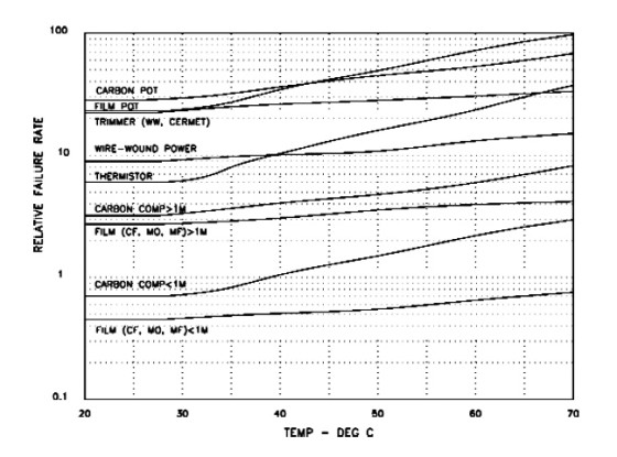
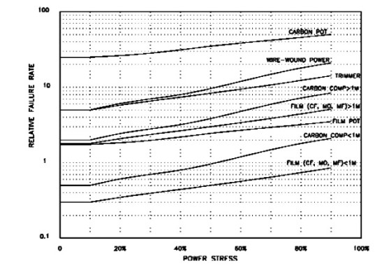
Their combined total in any piece of equipment can be the major contributor to heating, especially when large power resistors are used. Figure 4 shows the relative failure rates for resistors versus temperature. Figure 5 shows the relative failure rates for resistors versus power. Note the large jump in failure rates when you use values larger than 1MΩ. From a reliability standpoint, it makes sense to use two lower values in series rather than one resistor of 1MΩ or more.
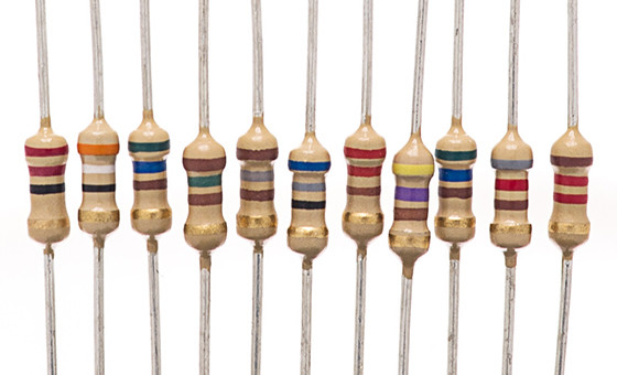
Carbon Composition Resistor
Carbon composition resistors are very reliable electronic components, with excellent RF performance. They usually fail when overheated or overly stressed due to shock or vibration. Composition resistors are considered to be general purpose resistors, available in tolerances from ±5% to ±20%. They should not be used in critical applications where environment changes can be expected.
The effects of humidity, temperature, and pressure, as well as normal aging, can cause a composition resistor to decrease as much as −15% below its specified tolerance. Every resistor acts as a noise generator whose mean square AC noise voltage is directly proportional to the value of the resistance. Johnson noise, also called thermal noise, occurs in all conductors as a consequence of the random motion of electrons. In addition, at low frequencies, the noise power varies inversely with frequency.
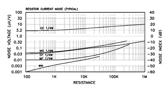
A common term for this type of noise is 1/f noise, or excess noise, since it exceeds Johnson noise at frequencies below a few hundred cycles. The root-sum-square total of noise currents (including those in tubes or semiconductors) will determine the noise floor in audio equipment. Figure 6 shows the relationship between resistance and total current noise in the fixed resistors discussed above.
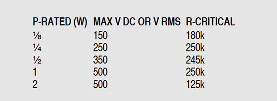
As you can see, carbon composition resistors have a much higher excess noise value than the other types of fixed resistors, and it increases with time and temperature. Carbon composition resistors are also sensitive to applied voltage, and have voltage limits based on case size rather than power ratings. The point where the applied voltage limit changes from power to voltage is called the critical resistance, listed in Table 1.
Film Resistors
Film resistors are made by applying a thin layer of resistive material to an insulated form. The most commonly used film resistors can be divided into types according to the materials used: carbon-film, metalfilm, metal-oxide and cermet (a combination of ceramic and metal materials), which have the best reliability of all the resistor types. The spiral pattern cut into the resistive film increases the inductance, limiting their use at high frequencies. Like the carbon composition types, film resistors also have critical voltage limits.
Carbon Film, Metal Oxide, And Metal Film
Carbon film resistors have improved noise and stability performance over the composition type, and tolerances of ±5%. Metal oxide resistors are a bit noisier than carbon film types, but have tighter tolerances, down to ±2%, and better stability. Metal film resistors have very tight tolerances (1% to 0.1%) and excellent temperature stability.
If a metal film resistor is exposed to excessive voltage, ion migration can occur between adjacent resistance stripes. This can cause an increase in resistance in the more positively biased portion of the package. Moisture and elevated temperature can accelerate this ion migration, and can produce localized changes in the metal film thickness or width.
Thermistors
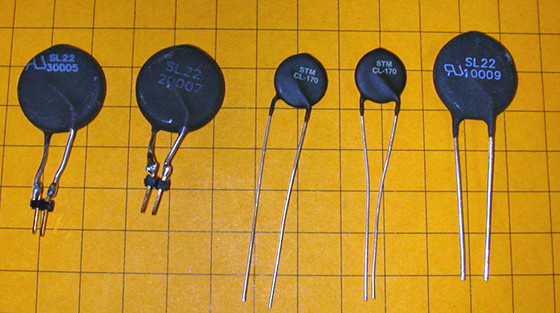
Thermistors are temperature-compensating devices whose resistance change with temperature is designed to track that of other devices, such as semiconductors. Ideally, the unavoidable de-crease in forward voltage drop with temperature in diode and transistor junctions is offset by the deliberate opposing change in resistance of the thermistor.
Wirewound Resistors
The wirewound resistor is the most stable resistor type, with commercial tolerances down to 0.1% or less. Wirewound resistors are constructed by winding a nichrome resistance wire around a ceramic insulated form and covering the package with a protective coating. Flameproof versions are available to meet fail-safe requirements.
Conventional wirewound resistors are highly inductive. Special noninductive types are available, with the winding applied in opposing directions to cancel the inductance, although this technique is not completely effective at high frequencies. Their predominant failure mode is an open in the wire resistance element, more prevalent as the resistance increases. Turn-to-turn shorts are also possible due to accumulation of dirt, dust, or a break in the outer coating. Moisture can cause corrosion of the end connections.
Variable Resistors
High-wattage variable resistors, or rheostats, were once used in audio to adjust filament and plate voltages, and are still used in L- and T-pads for adjusting remote loudspeaker volume. We will concern ourselves here with the low-wattage variable resistors commonly referred to as controls or potentiometers (pots). A potentiometer uses a continuous resistive element with a sliding contact that traverses the element in a straight or circular path. A pot is normally adjusted by a rotary shaft, or by means of a lead screw that is adjusted by a screwdriver.
Variable resistors may have carbon, cermet, film, conductive plastic, or wire-wound resistor elements. Small, precision (sometimes multi-turn), adjustable resistors are called trimmers or “trimpots” and are used for fine adjustments and calibrations in low current applications.
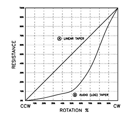
Most variable resistors have a linear “taper,” in which the change in resistance is linear with wiper travel. Audio controls are available with an audio taper, in which the change in resistance is logarithmic with wiper travel (Fig. 7). Noise voltage is more complex than with fixed resistors due to the additional noise variable introduced by the wiper.
Carbon composition elements are the most common type of potentiometer. They are analogous to carbon fixed resistors in that they use a mixture of powdered carbon and organic binders, fired on a ceramic substrate. They can be easily formulated in any type of taper (linear, audio, log, reverse log, and so forth).
Although they have (theoretical) infinite resolution, they change value with temperature and humidity. Excessive humidity may cause an increase in resistance. A composition resistor element may wear after extensive use, and the wear particles may cause high resistance short circuits.
Cermet elements are a mix of fine metal and metal oxide particles. They have excellent temperature stability, but low adjustability wear. This limits their use to trimmer pots in which frequent adjustment is not required.
Conductive plastic is made by compounding a low-friction plastic (polyethylene and/or polypropylene) with carbon and other materials. The resulting resistor element is a very smooth film, allowing extremely high resolution, low noise, and extended service life. Many high-end audio controls — in both linear and audio taper — use conductive plastic elements.
Wirewound elements are made the same way as fixed wirewound resistors, and have the same high degree of temperature stability. Since each turn of wire adds additional resistance, they change value in discrete steps as the wiper moves from one winding to another. Disadvantages are a lower life expectancy and higher electrical noise due to abrasion. They are only available with a linear taper.
Multiturn trimpots have two advantages over single-turn types. First, the lead screw mechanism uses a slip clutch at each end making it impossible to overpower the end stop and damage the pot. Second, the small adjustment screw opening in the case (sealed by an O-ring in the better pots) keeps dirt and contaminants out of the wiper/element.
The number of contact points directly determines the current-carrying capacity of the contact, its noise, the apparent contact resistance, and its operating smoothness. Higher quality pots use a “multi-finger” contact group of aligned contact springs, each providing a discrete point of electrical continuity on the resistive element. Inadequate contact force will result in poor contact resistance, while too much force will cause excessive contact and film wear, decreasing the useful life. While lower cost pots use base metal nickel-chromium and nickel-tin alloy wipers, precious metal alloys give the best electrical performance and life.
In instances where the pot wiper is connected to one end of the element, designers must consider the effect of an open wiper on circuit operation. The bias spreading adjust pot in power amplifiers must be positioned so that an open wiper will decrease the bias current (away from Class-A) to prevent overheating the output devices.
Motorized potentiometers are often used in stereo equipment with remote control capabilities. These consist of standard potentiometers with a drive motor integrated onto the pot stack. Multichannel home theater receivers use digital integrated-circuit pots.
Semiconductors
The manufacturing process for semiconductors of all kinds is carried out in a tightly controlled clean-room environment. Despite the best efforts to prevent contamination, semiconductor manufacture is a highly specialized multistep process, and minute flaws can be introduced along the way. Semiconductor materials provide the ability to control their conductivity by controlling the number of free electrons in the material. The leakage current flow in a semiconductor increases exponentially with temperature. In addition to the leakage current effects, the aluminum metallization used to make internal circuit connections reacts with the other materials. This can cause electro-migration and degrades the connections, eventually causing them to fail.
Uncontrolled leakage current flow results in internal heating of the device junction, which in turn produces more leakage current. The device may reach a point where, if the external impedance does not limit the current flow, the device will fail due to thermal runaway. The monolithic structure of modern semiconductors ensures that the die itself will always fail short. If sufficient fault current is available, the device
may then fail open.
This “burnout” is often a catastrophic failure (eruption) that masks any evidence of the original cause of failure. The current required to open a device may range from as little as 60mA for a low-voltage UHF Schottky diode to kiloamps for a really large diode or thyristor. Photoelectric effects can cause improper operation if light gets through the device package due to voids or other defects. Photocurrent increases with higher light levels.
Other degradations can cause misoperation: decreased diode peak inverse voltage (PIV), decreased gain, increased noise, increased reverse leakage current, and increased junction voltage drop. A change in junction capacitance or reverse recovery time seldom occurs. Low-noise devices are characterized by larger junction areas than general purpose devices. If the gate of a FET or FET-input op amp is driven positive so that it is caused to draw current, the noise performance of the device can be permanently degraded. Precision devices that are exposed to electrostatic discharge (ESD) or high levels of RF energy can also be permanently degraded, even if failure does not occur.
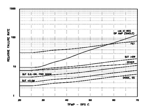
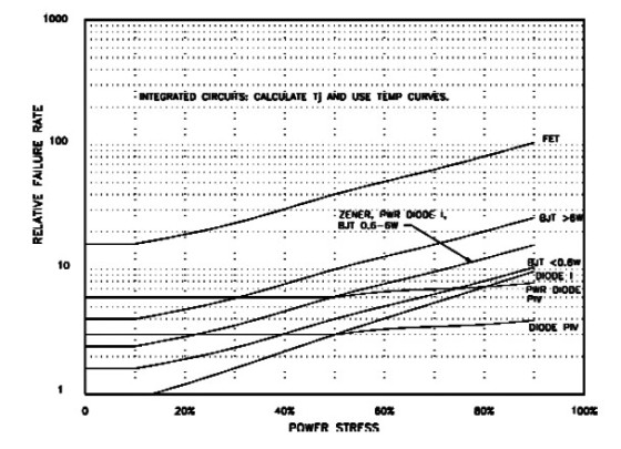
It’s not good practice to use the microwave to dry the Walkman you dropped in a puddle! Figure 8 shows the relative failure rates for semiconductors versus temperature, while Fig. 9 shows the relative failure rates for semiconductors versus electrical stress. Note the vertical axis scale. Semiconductors have failure rates an order of magnitude higher than those of passive components.
Electrical stress is not used as a failure rate factor for microcircuits. You must calculate junction temperature and apply the temperature factors. Digital ICs have their electrical stress pre-defined by their fixed 3.3 to 5V DC supplies.
Diodes
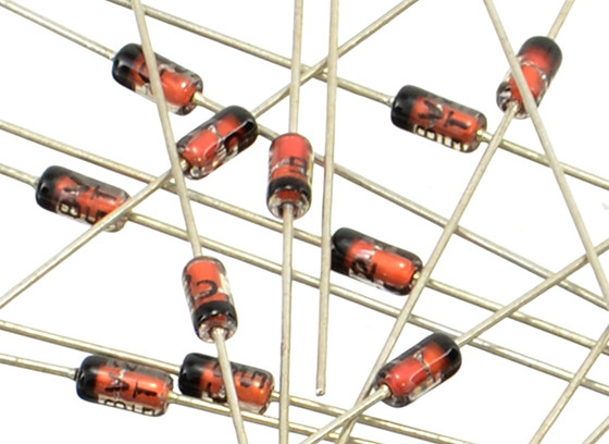
The principal failure modes encountered in diodes is a short. Small point contact or RF diodes may open at the lead attach point, but the most common die failure is a short. As with most failure modes, if sufficient current is available a shorted diode will burn open.
Zeners
Zener, or regulator, diodes work in two different ways. True zener diodes are available only below 7V DC. The farther you go below 5V DC, the worse a zener diode performs. They have a negative temperature coefficient (TC), and the zener voltage changes considerably with current. Zeners with voltage ratings of 5.1 to 5.6V perform best, with near-zero TC and very little change in reverse voltage over a fairly wide range of currents.
Zener diodes rated more than 7V DC are called avalanche diodes. An avalanche diode’s voltage varies with current, and the TC increases in the positive direction with increasing voltage ratings. If zener voltage is a critical parameter, temperature-compensated types with tight tolerances are available.
Small Signal Transistors
Transistor degradation can be characterized by high leakage, high saturation resistance or voltage, low beta or transconductance, or low breakdown voltage. PNP bipolar junction transistors are subject to inversion, a phenomenon associated with high temperature reverse bias (HTRB). A P-type region forms at the base, resulting in an extension of the collector region, causing high reverse leakage current.
Power Semiconductors
The limitation on the power handling capability of diodes, bipolar transistors, and MOSFETs is the peak junction temperature. Power devices have all the degradation mechanisms of small-signal devices, with added deterioration introduced by thermal cycling. Power devices can also fail when the mechanical connections to their heatsinks degrade (reduced mounting screw torque, deterioration of the heatsink compound, damage or oxidation at the mounting surfaces).
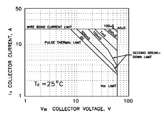
Bipolar power transistors, being minority carrier devices, have an additional limitation, called second breakdown4. Figure 10 shows the active-region safe operating area (SOA) curve with its four limiting regions for a 2N3772 NPN power transistor at 25°C. The inner DC limit is bound by the horizontal collector current line (20A), the diagonal thermal limit power parabola line, and the vertical collector voltage line. The thermal limit lines move outward for single pulse applications of decreasing duration, based on the thermal time constant of the transistor.
You can also see additional breakpoints in the 500ms and 100ms pulse lines, which represent the second breakdown limit, where VCE must be reduced below the level that is required for purely thermal reasons. Second breakdown is caused by the tendency of a bipolar transistor to develop localized hot spots when the collector current flow becomes concentrated at high VCE.
Exceeding the second breakdown limit causes thermal runaway in the collector region, which can destroy the device. The SOA curve is based on the ab-solute maximum voltage, power, and current ratings for the device. Operating anywhere on the power limit line will produce the maximum junction temperature, which
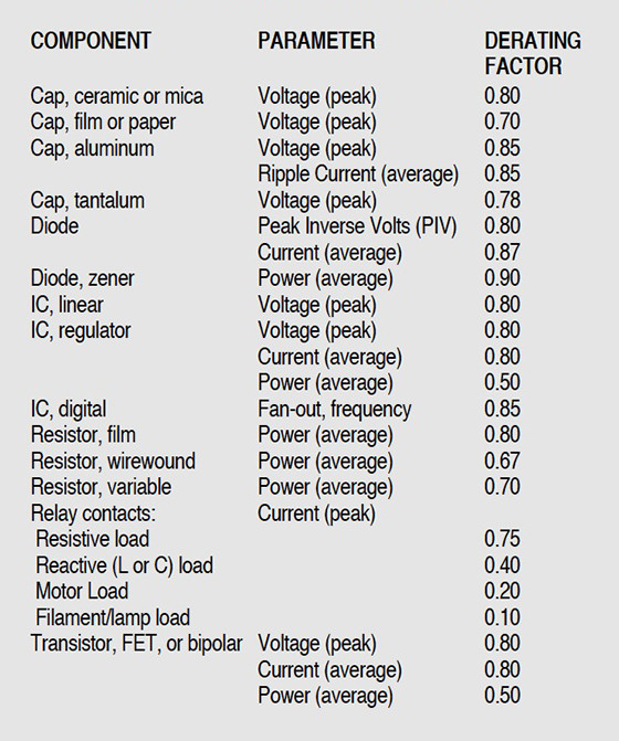
is not a good practice. The derating factors in Table 2 should be applied to this curve. Further power derating is required for operation above 25°C, and some manufacturers provide additional ambient limit lines for the thermal limit portion of their SOA curves. You can see that making the most effective use of a power transistor without seriously degrading its reliability is not a trivial task.
Microelectronics
The failure rate in Fig. 8 for op amps is for an average single unit. The actual failure rate, as with all integrated circuits, is based on the number of transistors in the design. FET-input devices are very sensitive to static electricity.
Now that the features and interconnects in digital integrated circuits have gone sub-micron (less than one-millionth of an inch), with more and more layers, electro migration has become a real problem. Despite the fact that the current in these devices is milliamps or less, the current density (amps/square mil) is high enough that the moving electrons collide with the aluminum metallization, producing molecular level holes in the chip’s interconnections.
When the current density in the reduced area becomes high enough, the aluminum can melt, causing a failure of the device. Another failure mechanism occurs when the displaced aluminum atoms cross over an area of insulation in the chip, causing a short circuit. Part 3 wraps up this look at electronic circuit components.
References
4. “Power Amplifier Stress and Power Handling Limitations,” Burr-Brown application bulletin AB-039, April 1993, www.ti.com
This article series was published in audioXpress, from November 2001 to January 2002.


