Specifically:
1. Cost!
2. Internal volume behind the speaker
3. Good speaker sensitivity for low battery drain
4. “Line of sight” between the front of the speaker and the listener
5. Adequate amplifier power with low power consumption and low heat
The goal of this article is not to teach how to design a good microspeaker, but rather to provide information on how to design a good mobile audio system, touching upon speaker design and speaker enclosure techniques.
The Traditional Microspeaker
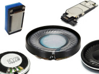
The need for small extended range speakers is being driven by laptop computers, hands-free car kits, portable players, mobile Internet devices, and smartphones. Today, the challenge is for the 1″ to 2″ diameter microspeaker to reproduce natural voice and music, have reasonable sensitivity and power handling, and be able to reach satisfactory sound levels. All this while maintaining a cost range from $0.25 to less than $1 for most types.
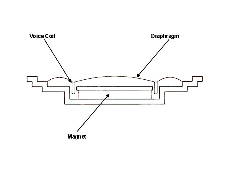
The headphone and earphone speaker is a derivative of the microspeaker, with critical variations that we will discuss. Generally, in microspeakers and headphones, a single diaphragm forms the surround, diaphragm, and dust cap (see Figure 1). The voice coil is typically bobbin-less (also known as monolithic or self-supporting). This is a one-point suspension with only surround compliance and no spider.
Design, Construction, and Operation
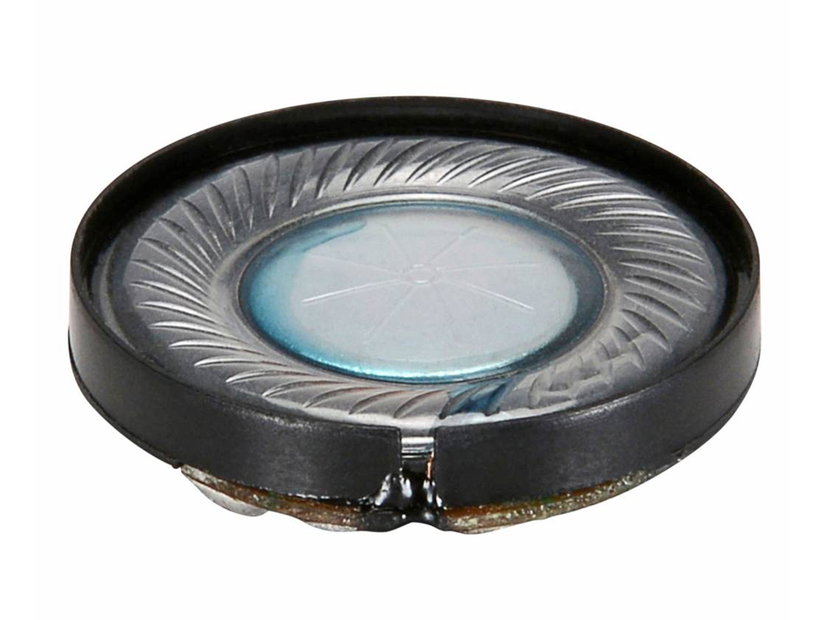
Microspeakers use a fabric or film diaphragm without a separate dust cap, and do not use a spider. The voice coil is located at the dome/dust cap and the outer ring of the surround forms the compliance. This doughnut shaped diaphragm often has molded-in tangential creases for anti-rocking and stiffness. This technique is also common to both headphone and dynamic mike elements.
Microspeaker sensitivity can be quite low. For this reason, the general practice for measuring these transducers deviates from the accustomed 1m/1W standard. Instead, the microphone may be placed 10cm from the speaker and driven by a 1W test signal. In spite of the close proximity of the microphone, typical sensitivities for microspeakers in this test setup are only 85-87dB.
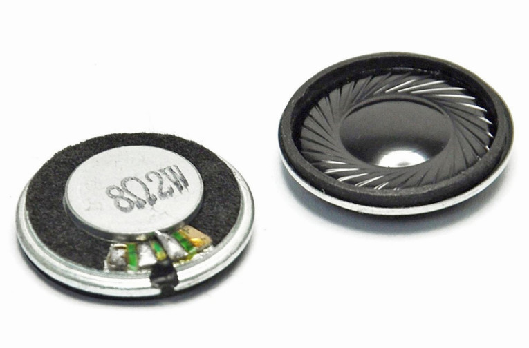
For micro-miniature speakers popular in cellphones, the sensitivity is 68dB at 1W/1m — quite low — and the F0 is 1000Hz. Free air resonance for most microspeaker designs typically runs in the 500-700Hz range, but some 40mm designs reach below 300Hz. Diaphragm thickness is a key factor of both bandwidth and sensitivity. While the mini speaker has separate surround compliance, the compliance of the microspeaker is typically a corrugation of the diaphragm material at the outside edge. Alternatively, the diaphragm has a contour or roll between the voice coil and the outside edge, and the entire area flexes as the compliance.
If you think about it, since the diaphragm and surround are common, as the thickness drops, the compliance increases. With the mini-speaker, as the thickness of the cone is reduced, the moving mass drops and the midband efficiency increases, while the bass (due to over motoring, i.e., a rising Qes) drops down. On microspeakers, the opposite is true. As the diaphragm thickness drops, the bass really comes up, while the midband and top-end also rise. Distortion also tends to rise, as the diaphragm becomes too flimsy and there is less control of the diaphragm assembly. A key factor to control the bass response and F0 and Q is the acoustic resistance scrim, which we will cover in the next section on components.
Components
1. Diaphragm
The diaphragm is the component of the speaker that radiates the sound. It is the most important contributor to the sound quality of the speaker. Aside from its sound quality, the issues of stability, consistency, and temperature tolerance are also important considerations.
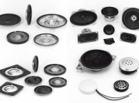
Microspeakers of 40mm diameter typically use less than 2 mil (50 microns) diaphragms and often as thin as 25 microns, while headphone elements use 25 microns or 19 microns. Tiny earphone diaphragms of about 9mm diameter are less than 12 microns. While on the topic of film thickness, dynamic mike diaphragms are around 12–16 microns, and ECM condenser mike diaphragms around 2 to 8 microns. While diaphragms come in many different sizes, there are two common shapes: round and oval (“race track”). These shapes both work well, but high aspect ratio shapes for oval speakers can have more problems. Extremely shallow diaphragms are weaker, but contours can provide strength.
2. The Voice Coil
Most voice coils in microspeakers are formed of a helically wound wire of two layers (one down and the other back up). Depending on the speaker design, the coil is self-supporting or has a former material coated with a thin layer of adhesive on one side, then B-staged (dried at low temperature without curing the adhesive).
These materials may be cut to the required dimensions from master rolls or large sheets of material, using a shear, roll slitter, rotary die, or steel rule die. Although some users cut materials in-house, the majority receive it cut into “blanks” by the vendor (converter), because it requires a high degree of accuracy.
These voice coil blanks are wrapped around tubular steel or aluminum winding-mandrels (also called arbors, or tools) at which point their name changes from blank to former. The former is wetted with solvent (such as acetone/alcohol) either by brush, spray, or by in-line wetting of the insulated, adhesive coated wire with solvent.
An alternative production technique involves using a former that has been spiral-wound into tubes (or the resin extruded into tubes) and chopped to final dimensions. Well made tubular formers can simplify automated assembly, although poorly made tubes can be a disaster. Spiral-wound voice coil tubes are available in various papers, Nomex, and as laminates of Nomex and aluminum. Tubular formers are wound with B-staged adhesive on the outside, and tubular collars have their adhesive on the inside.
Conductor — Typical microspeakers use copper (Cu) alloy wire. Alternatively, copper clad aluminum wire (CCA or CuAl) provides lighter weight, resulting in about +1dB sensitivity. CCA wire is weaker and softer than Cu wire, so special techniques are used by the speaker factory for reliable construction.
Insulation coating/temperature rating — The conductor (wire) has a film insulation coating. In the past, 105° C was adequate for microspeakers, but with higher power amplifiers in mobile products 150° C or 180° C is becoming more common. The wire insulation film thickness remains the same as 105° C coating, but a higher performance insulation coating is used for this increase in thermal power handling.
Outer bond coat (lock and SV) — The adhesive for the voice coil wire is often coated onto the insulated wire. The adhesive is solvent activated during the voice coil winding operation. General use “lock” adhesive is typical, but for higher performance microspeakers, SV high temperature outer bond coat is used.
3. The Magnet
Ferrite has never dominated mini and microspeakers as it has the rest of the speaker industry. Because of their inherent magnetic self-shielding, Alnico or neo slugs in a steel pot structure were commonly used in CRT computer monitors and TVs. Another issue is that a decent ferrite structure will be larger in size and weight than its neo counterpart; this has implications toward mounting depth, available enclosure volume, and overall product weight.
4. The Acoustic Resistance Scrim
The microspeaker diaphragm radiates almost as much backward as forward. Because there is not a damper (spider) to control the settling time (decay) of the diaphragm, a scrim of woven or non-woven mesh is used to cover the open “windows” of the basket. The higher the acoustical resistance of the mesh, the tighter the resulting bass response. Too closed, and the bass will be thin, too open and the diaphragm will be underdamped and under poor control. Woven scrims provide significantly higher consistency and are typically used for higher quality products. Saatitech of Italy is the source for acoustic meshes for headphone vents, wind screens, microspeaker meshes, and so on.
5. Ferrofluid (optional)
Ferrofluids have been used in traditional loudspeaker designs for over 30 years. Recently, some innovative approaches to the application of ferrofluid in microspeakers have found commercial success. Two examples follow.
Coating the pole piece: Because the microspeaker has a single-point suspension, its voice coil is more susceptible to radial and rocking modes in the air gap, which increases the potential for the coil to come into contact with the metal parts of the magnet structure.
A high viscosity coating — specifically ferrofluid — on the pole piece minimizes contact-related buzz but does not fill the ID or OD of the air gap so there is no fluid splash or parameter shift. Production engineering of ferrofluid for microspeakers, hearing aids, and headsets is still a proprietary technology, but has been used in mass production by both Sennheiser and Knowles.
Additionally, this approach can help us to improve the sensitivity of the design by reducing the width of the air gap.
a. Tighten gap to increase B (flux)
b. Bobbin-less self-supporting voice coil (no bobbin mass)
c. Thinner gauge wire
d. CCA wire
e. Coat the pole piece with ferrofluid
Single-sided filling: In this approach, the ferrofluid is applied either to the space between the coil OD and top plate or coil ID and pole piece, but not both. By filling one side of the gap, you are able to take advantage of the benefits of ferrofluid (heat transfer, damping, and voice coil centering) without the usual concerns for added venting to prohibit ferrofluid splash.
The Sub-Enclosure
With the speaker selected for the design, what’s next? The raw driver might have acceptable performance when measured on a standard baffle, but things can change dramatically once you place the driver into the product. The space behind the driver (size, shape, proximity to the driver, and so on) can have a profound impact on the performance of the driver as can its mounting location relative to the user. Therefore, the designer must pay close attention to where the speaker will be located on the product and what is going on around it.
Again, we are preaching our “systems approach” to audio design, where enclosure design should be considered during the industrial design and internal layout portion of the development process. More often than not, the audio designer is presented with a completed industrial design and layout and is told to make the system work within these constraints. However, if consideration for the audio system is made earlier in the design process, the end result will be a better sounding/performing system.
Ideally, the speaker should be facing the user — not away or downward. Downward-facing speakers are the latest trend in large-screen TVs — Ughh. Direct sound is always better and more intelligible than reflected sound. If there is a microphone in the system, speaker and mike location should be optimized to avoid feedback.
A grille or screen is needed to protect the microspeaker’s delicate diaphragm from potential damage. While it is easy enough to design a bunch of holes into the housing mold tool and call it a “grille,” oftentimes the thickness and open area of the grille are not optimized for good audio performance. As a rule of thumb, the more open area you can have in front of the speaker, the better. Thirty percent open is generally accepted as the minimum recommended area. Anything less than 30% can noticeably impact the speaker’s performance, particularly its time (impulse) response. In addition to the percentage of open area, another important dimension is the grille’s thickness. An overly thick grille can lose its acoustic transparency and color the output of the speaker. Ideally, an open mesh screen or perforated aluminum grille in front of the speaker will yield the best results, but this may not always be practical.
As mentioned earlier, what’s going on behind the speaker can have a significant impact on its output. There are several options available to the designer: Use the entire product enclosure for internal back chamber. While this is the simplest approach, it is the least desirable from a performance standpoint. By not isolating the speaker from the rest of the internal volume, you are exposing the speaker to losses caused by air leaks in the enclosure as well as increasing the potential for unwanted buzzes and rattles.
Create a sub-enclosure behind the speaker. By creating a sub-enclosure behind the speaker, you can balance the Thiele/Small parameters of the speaker (electrical and mechanical losses) with that of the enclosure to optimize the low-frequency response from the speaker. A sub-enclosure can also help to isolate the speaker from the rest of the chassis, reducing the potential for spurious buzzes and rattles.
The type of enclosure depends on the designer’s preference and available space. An acoustic suspension design will be the simplest to implement, but if a ported or passive radiator design is required, then the complexity of the sub-enclosure will increase accordingly. VC
This article was originally published in Voice Coil, May 2010.
Original title: Mobile Audio Sound System Design, Part 1
Article has been edited from the original version.
Read other articles from Mike Klasco on Microspeakers.
References:
SAATI - www.saati.com/en/markets/consumer-electronics
Knowles - www.knowles.com
Ferrotec - www.ferrotec.com