As Svante Littmarck, COMSOL President and CEO details, “Our customers strive for a highly efficient product development cycle. With the multiphysics modeling capabilities of our software, they can create innovative products faster and at a lower cost than ever before. This exciting release is a result of a big focus on quality and major advances in new powerful modeling methods, increased speed, and user-driven enhancements.”
New in Acoustics
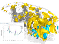
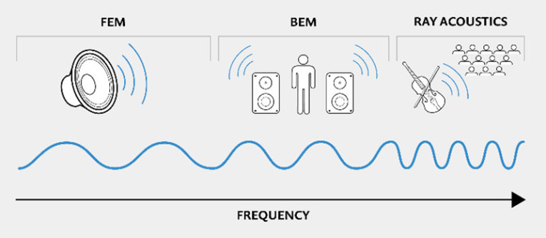
COMSOL 5.3a offers acoustics analysis based on the boundary element method. “The recent addition of the boundary element method in COMSOL Multiphysics will enable us to model large acoustical radiation problems, such as, exterior sound reproduction for electric cars” comments Martin Olsen, Principal Engineer, Research, at Harman Lifestyle Audio. “We are pleased with the full range of methods available in COMSOL, from FEM and BEM, to ray tracing. The possibility of coupling BEM to FEM creates a highly versatile simulation environment for the automotive audio industry.” Acoustic engineers will get unprecedented modeling power by being able to analyze the full range of acoustic frequencies from the lowest bass notes to ultrasound, in addition to all of the possible multiphysics couplings available in the software.
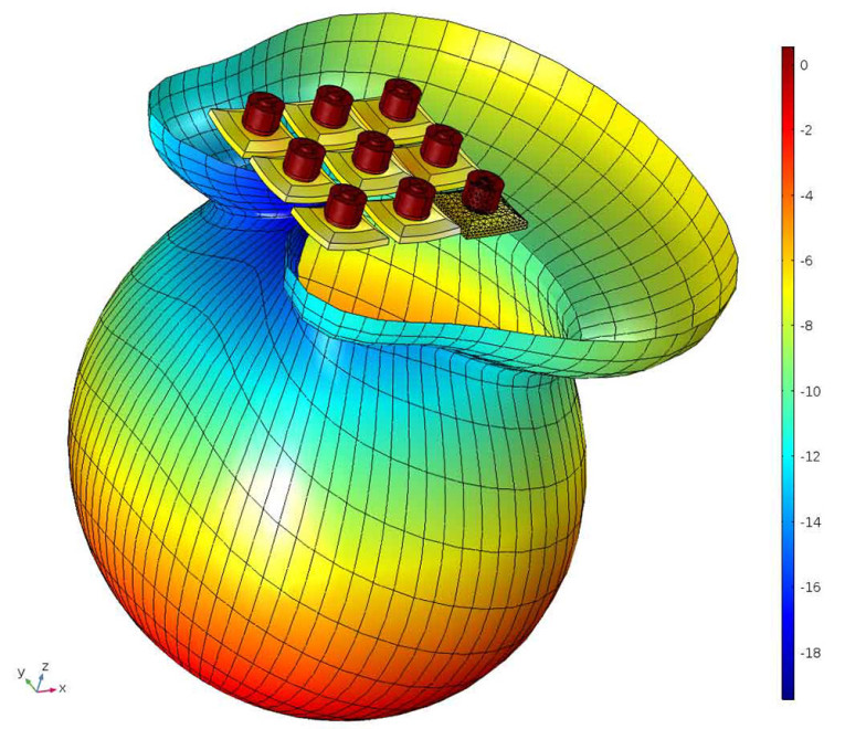
The boundary element method (BEM) is now included in the Acoustics Module in the form of a new Pressure Acoustics, Boundary Elements interface. The new interface, available in 2D and 3D, is well suited for frequency-domain simulations solving the Helmholtz equation with constant-valued material properties. Additionally, it is implemented as a scattered field formulation with the option of adding a Background Pressure Field for modeling scattering problems.
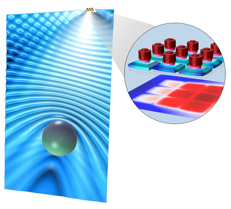
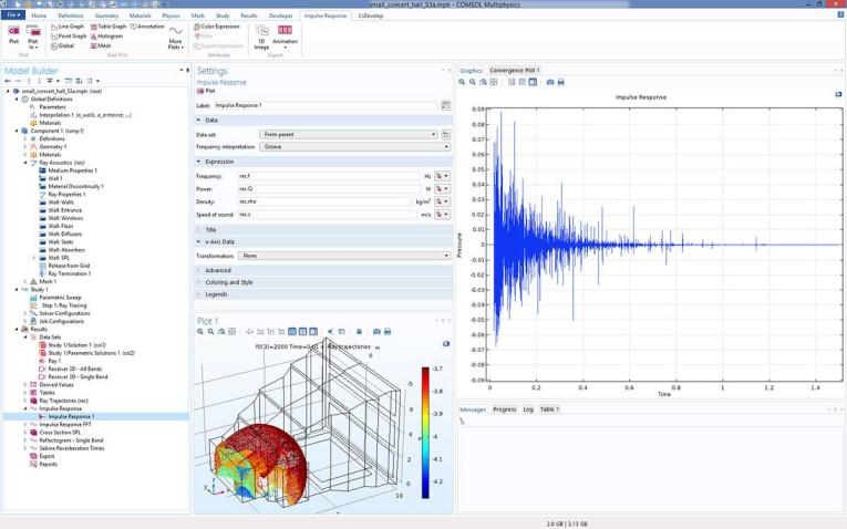
Users can now postprocess the impulse response from a ray acoustics simulation with the new Impulse Response plot, which reconstructs and visualizes the impulse response based on receiver data. The new Receiver data set collects the ray information and serves the purpose of a virtual microphone, providing data for the Impulse Response plot.
The Receiver data set calculates the virtual intersection between rays and a sphere of finite size. The sphere size can be determined either from an expression (based on the number of rays, the room volume, and the source-to-receiver distance) or it can be entered manually. The data set determines ray arrival time, recorded intensity, and frequency, and it is used by the Impulse Response plot. This data set can also be exported for use in an external tool. There is an option to enter a user-defined directivity for the receiver. The receiver location can easily be changed and it is not necessary to solve the model again to change the recording location for the impulse response.
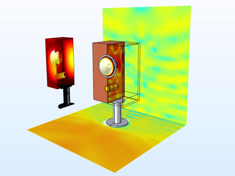
The Impulse Response plot interprets the ray data from the receiver using an octave, 1/3 octave, or 1/6 octave frequency resolution. The same resolution should be used for all sources and wall properties, for example, the absorption and scattering coefficients, source power, and so forth. The plot generates the impulse response with a default sampling of 44,100 Hz.
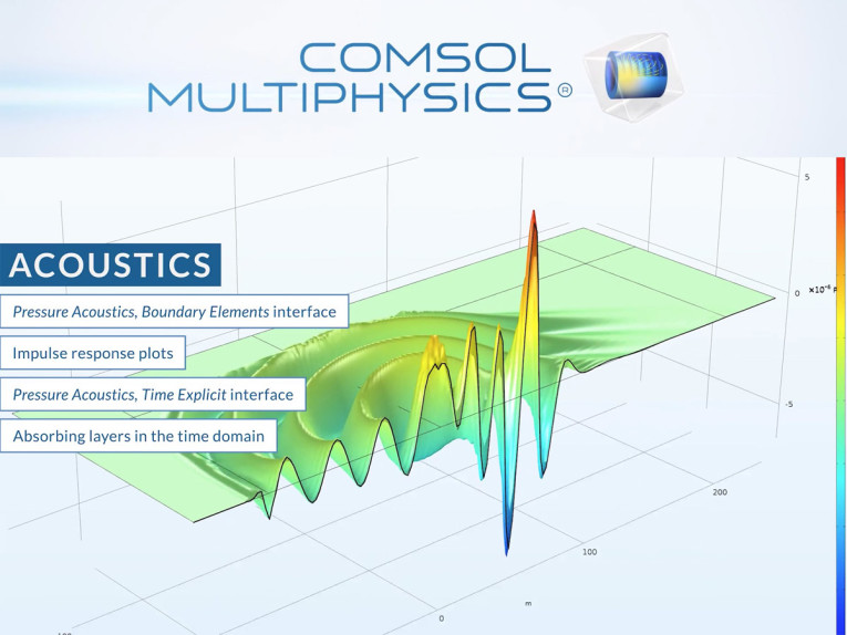
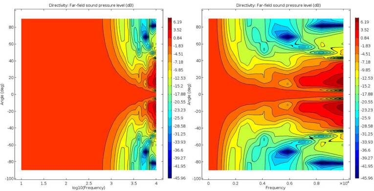
A new physics interface, Pressure Acoustics, Time Explicit, based on the discontinuous Galerkin (dG-FEM) formulation, employs a time-explicit method that is memory efficient, with low memory consumption. The interface can be used to solve large, transient, linear acoustic simulations that contain many wavelengths, and is well suited for time-dependent simulations with arbitrary time-dependent sources and fields. There is an additional Background Acoustic Field option for modeling scattering problems and you can use absorbing layers to set up effective nonreflecting-like boundary conditions. The exterior scattered far-field can be calculated by combining the Far-Field Calculation feature with a Time to Frequency FFT study step. The interface is available in 2D, 2D axisymmetric, and 3D. Important application areas for this new interface include transient propagation of audio pulses in room acoustics and scattering phenomena involving large objects relative to the wavelength.
The Pressure Acoustics, Time Explicit interface solves the linearized Euler equations assuming an adiabatic equation of state. The dependent variables are the acoustic pressure and the acoustic velocity perturbations. No attenuation mechanisms due to bulk losses are included in the interface. Losses at boundaries can be modeled with impedance conditions for losses of the resistive type.
The Pressure Acoustics, Transient and the Pressure Acoustics, Time Explicit interfaces now have a built-in option Plane wave (monochromatic) to define monochromatic plane waves as a background pressure field or an incident pressure field. The new option simplifies setting up this common wave form for transient simulations. If other types of transient fields are needed, the user-defined option allows the definition of any field based on an analytical expression or interpolation data. The new option also has a built-in ramp function that smoothly increases the amplitude of the wave over the first period, in order to ensure good numerical performance.
New Modeling Tools, Faster Solvers, Better Visualization
A framework for model reduction is available with the release of two methods, modal analysis and asymptotic waveform evaluation (AWE), for the reduction of the computational complexity of mathematical models. Users using LiveLink for MATLAB can get access to reduced models through a dedicated state-space export function. Many users, especially those involved with computational fluid dynamics (CFD) analysis, will experience up to 40% improved performance for algebraic multigrid (AMG) and 20% for geometric multigrid (GMG) solvers. Support for 3Dconnexion SpaceMouse devices makes model navigation easier. The color table Cividis, optimized for people with color vision deficiency, is now available for visualization of field quantities.
The new COMSOL Multiphysics 5.3a features a revolutionary new method for modeling capacitively coupled plasmas (CCP), based on a non-linear time-periodic formulation, reducing solution times of CCP simulations from weeks to hours. Those working in electromagnetics can now use the boundary element method to analyze magnetic fields in models with large volume-to-surface ratio, including infinite domains, with great accuracy.
Engineers designing smart metal devices, from biomedical to consumer products, can also now include a shape memory alloy (SMA) material in their simulations. A SMA material can be coupled to other physics such as heat transfer. Users will benefit from a solid-beam connection feature as well as a new technique to model thread forces for bolts using a dedicated type of contact pair boundary condition.
Robust Rendering in Simulation Apps, New Publishing and Administration Features
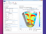
Apps with very large plots or many graphics windows will see improved rendering performances resulting in a more responsive user interface. COMSOL Server users will now have the option to login without a password within their corporate network, making it quicker and easier to run apps. The thumbnail image and description for an app can now be changed directly through the COMSOL Server web interface. Administrators can send global notifications to all users, for example, if the server needs to shut down for maintenance. There is a new cluster verification app installed by default in COMSOL Server that allows administrators to test cluster settings more conveniently. This app is also available in a regular COMSOL Multiphysics installation for floating network licenses.
COMSOL Multiphysics and COMSOL Server software products are supported on Windows, Linux, and macOS operating systems. The Application Builder is supported in the Windows operating system. To browse further features and updated tutorials included in version 5.3a, visit www.comsol.com/release/5.3a.
To download the latest version, visit www.comsol.com/product-download.
www.comsol.com


