Although VPI (www.vpiindustries.com) offers an accessory power controller to provide this function, the price was a bit steep. I decided to design and build a variable frequency AC supply to control the turntable’s speed rather than use a Triac or similar type of solid-state control circuit. Although these circuits are readily available at the hardware store, they are prone to generating noise that may be picked up by the cartridge.
I consulted my notes from several years ago when I rebuilt a General Radio Model 1311-A Audio Oscillator. This circuit, with minor modifications, formed the basis for designing and building a Variable Frequency Synchronous Motor Controller (VFSMC) suitable for driving the VPI motor. I went to my parts bin and pulled out a few components that were used to develop the 1311-A rebuild and assembled them on a prototype/experimenter’s board.
My calculations showed I needed to design a circuit that would meet the motor’s power requirements (11W) and allow for overhead. The LM386 power amplifier I used in the 1311-A was satisfactory to prove the concept; however, in deference to supplying the motor’s rated output power and driving a step-up transformer, I would need a more powerful amplifier.
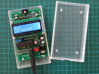
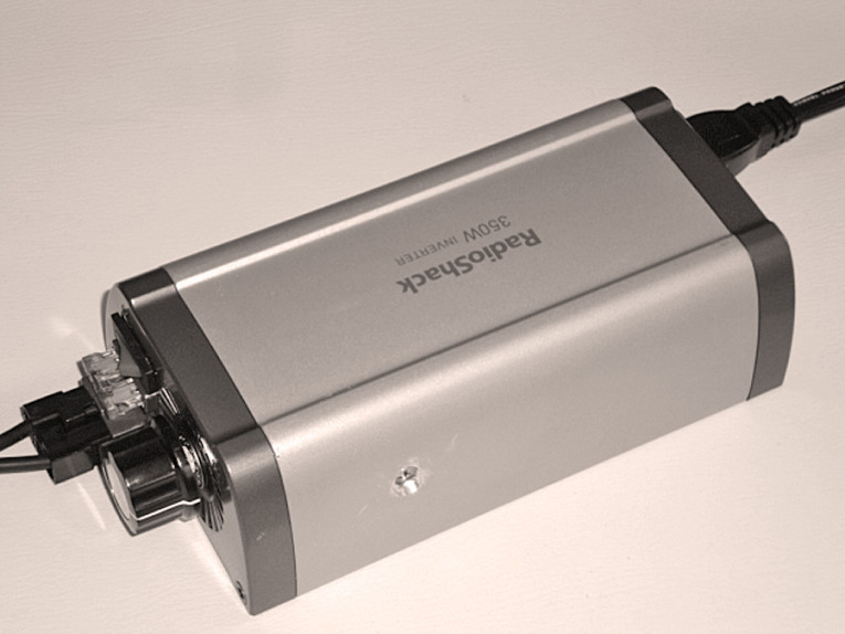
Substituting a resistor to simulate a load, and an old transformer I had laying around, I went through a few iterations of the circuit design to prove the concept and ensure the output was a pure sine wave and free from noise, with minimum harmonics. After prototyping I found an AC inverter, manufactured by Radio Shack, which provided a suitable enclosure containing: aluminum heat-sinking case, electrical outlets, fused inputs, on-off switch, and so on. This formed a basis for the VFSMC. I could build a circuit board, substitute a new transformer, and wire it back up to the existing 120V AC outlets. I only needed to modify the enclosure for my application (Photo 1).
Circuit Description and Operation
I used the same circuit I previously developed for the 1311-A oscillator. This circuit, which has proven to be very robust and reliable over the years for generating a sine-wave output, is based on an article by Maxim-IC, for their single chip 8th–order, low–power Bessel and Butterworth switched capacitor filters. The article is contained in Application Note 1999, “Sine Wave Generator is Crystal Accurate.” Maxim has published a few other application notes using the same method/scheme for generating sine waves from square waves1-3.
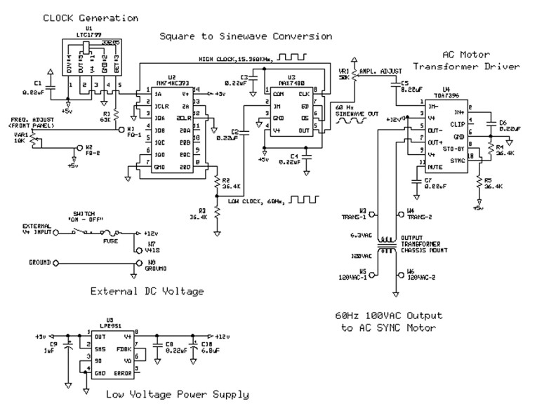
The application note states that sine waves are generated by filtering a square wave. A square waveform is composed of odd harmonics. Filtering out the odd harmonics leaves a sine wave composed of the fundamental wave. The IC filter selected requires a clock frequency at least 100 times the desired frequency. Rather than use a separate crystal oscillator and divider network, I chose to use a single resistor set point type of oscillator, part number LTC17994, manufactured by Linear Technology (www.linear.com). You may consider other options such as using a programmable microcontroller or similar logic-based device.
I chose a dual binary counter based on the design in Maxim’s application note. The dual binary counter5 divides the input square wave by 256. This provides a filter corner frequency meeting the 100x requirement of the filter. Because the desired output frequency is 60Hz, the equation for calculating the desired oscillator frequency is:
FOSC = 60Hz x 256 = 15,360Hz [1]
Next, I used the equation for selecting the resistor to set the oscillator frequency as follows:
RSET = 1 x 10¹¹/N/FOSC [2]
In reviewing the application note’s Fig. 2 RSET versus Desired Output Frequency, “N” was selected for a factor of 100. From the graph, I then substituted the values for these variables to give a desired oscillator set point resistor of:
RSET = 1 x 10¹¹ Hz/100/ 15,360Hz = 65.104kohm [3]
I consulted my Mouser catalog (www.mouser.com) and found a few fairly close resistor values. From my prototype experiments, I wanted to have a minimum of 2Hz adjustment in either direction from 60Hz. For this reason, I selected a standard resistor value slightly less than this: 61.9k ohm with 1% tolerance. I then selected a standard 5k ohm value, ±5% 10-turn potentiometer to provide fine frequency adjustments of ±2Hz.
Calculations indicate a frequency span of approximately 58Hz to 63Hz. You can achieve a tighter frequency adjustment span and tolerance by using a 64.9k ohm resistor and 1k ohm potentiometer.
Note: Measure the set point resistor prior to inserting/soldering into the circuit. If you use a 1% tolerance resistor, the value of the set point resistor should be okay, but if you design for the tighter frequency adjustment span, the value may be too large, and you may not be able to achieve 60Hz.
The two logic outputs (Fig. 1) are taken from the counter, “HIGH CLOCK” and “LOW CLOCK.” The “HIGH CLOCK” sets the corner frequency of the MAX7480 “8th-order, low-pass, Butterworth, Switched-Capacitor Filter,” and the second-stage binary counter “D” output sets the “LOW CLOCK” output frequency of the MAX7480 filter and is the frequency the VFSMC’s AC output is set to. The Dual Binary Counter, MM74HC393, datasheet is found at reference 5, while the MAX7480 datasheet is at reference 6.
The MAX7480 datasheet shows the “LOW CLOCK” output amplitude is too high. A resistor divider network, composed of R2 and R3, divides the 74HC393’s output voltage by two, or about 2.5V peak-to-peak. This keeps the input signal to the MAX7480 within its lower THD operating curve—see Fig. 11 and Table A of MAX7480 datasheet. The MAX7480 output is a sine wave with very low harmonic distortion and does not have the noise content that the truncated or modified sine-wave type DC-AC inverters have. Finally, the sine-wave output of the MAX7480 filter is run through a 50kohm potentiometer with the wiper AC coupled to the output power amplifier’s inverting input via capacitor C5.
I looked at several output amplifiers before finally settling on a bridge type audio amplifier, TDA7396. The attractive feature about this amplifier is that it is a self-contained “bridge” type of amplifier, operating off a single voltage supply, capable of driving low impedance loads like a transformer. This keeps the parts count down and makes the circuit easier to troubleshoot.
You can drive the TDA7396’s pair of outputs to a level of 45W, which is more than adequate for the motor’s required 11W. Additionally, the TDA7396 device has several built-in protection features. The LED fault indicating logic output circuit was not used in this design. The DIY VPI HW-19 turntable I have uses a Hurst Model PB, 600 RPM, 115V, 60Hz, 11W, AC Synchronous Motor, with part number “SP-2871.” The datasheet for this family of AC synchronous motors is found at reference 7.
Complementary outputs, + and -, from the TDA7396 power amplifier are connected to the secondary windings of an Acme Electric/Amveco Toroidal Transformer, model 62050. The transformer is rated at 15 volt-amps, which provides a design margin of more than 25% with respect to the motor’s maximum rated power. Primary windings are 115V AC, and the secondary windings are set for 7 to 8.9V AC, depending upon the load. The datasheet for this transformer is found at reference 8.

Build and Operational Measurements
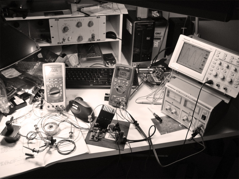
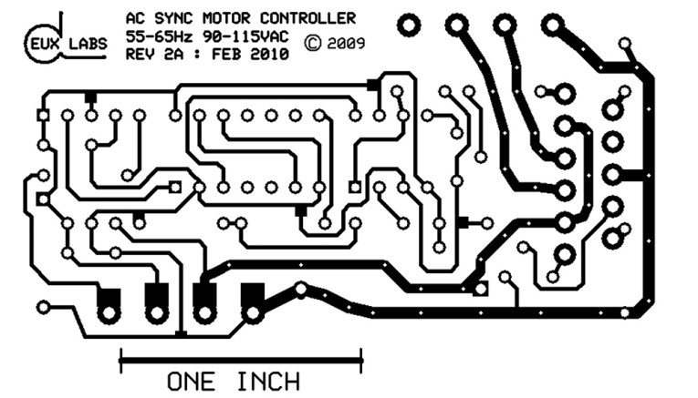
I designed, built, and tested an initial prototype circuit board (Photo 2). Except for an error in the PCB layout, the design worked as planned when assembled outside the Radio Shack AC-Inverter enclosure. I noted no other problems. I used two potentiometers to fine-tune the circuit’s final resistor values. The Hurst turntable motor operated perfectly over a frequency span of 53 to 68Hz.
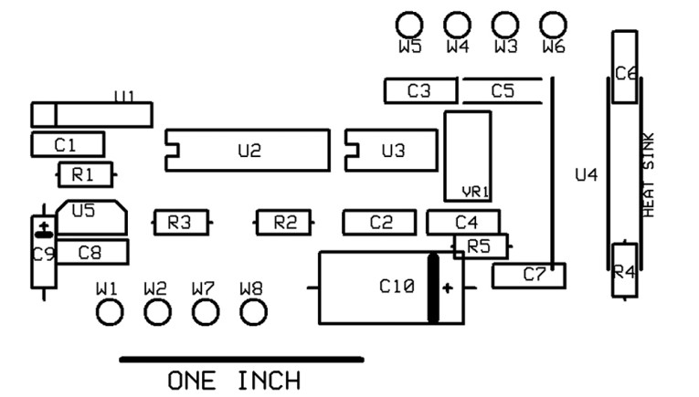
I did encounter a minor glitch when I connected the output of the TDA7396 to a 10k ohm load rather than a transformer. The TDA7396’s protection circuitry had kicked in and placed the amplifier in shutdown/standby mode. After troubleshooting the output fault circuit on the TDA7396, I discovered it required a much lower load on the bridge circuit’s outputs in order to function properly. I changed the output load resistor and performed initial measurements. Subsequent to passing those measurements, I connected the output transformer with a 3k ohm load simulating the motor for test purposes (Photo 3).

For the final build, I decided on a simple circuit board, using “leaded” components. This presents a minor problem with the LTC1799 oscillator, which is only available in the SOT 23-5 package. I found a suitable 5-pin SIP adapter at Digi-Key, part
no. 33205 (www.DigiKey.com). I designed a long and narrow circuit board to fit within the precut PCB slots inside the Radio Shack Inverter housing without any modifications. The narrow circuit board also allows clearance room for the toroidal transformer. The transformer is mounted roughly in the middle of the enclosure, leaving room for clearance between itself and the AC outlets mounted in the enclosure’s endcap, and room for the circuit board on the other side.
I drilled a no. 8 size clearance countersunk hole on the bottom of the housing for attaching the toroid transformer. Although snug, there was plenty of room around the transformer for routing of internal wires and placement of the VFSMC circuit board.
Next, I drilled a 0.25" diameter clearance hole in the enclosure’s second plastic endcap, adjacent to the on-off switch, to mount the 2k ohm frequency adjustment potentiometer (Photo 4). Then I drilled a no. 8 size clearance countersunk hole into the exterior surface perpendicular to the heatsink-mounting slot (channel) inside the Inverter housing. The TDA7396 heatsink mounts up against the mounting slot and is secured in place by an 8 x 32 x 5/8 Phillips head screw (Photo 5).
I made no other modifications to the enclosure. The DC voltage input connection was retained, along with the two AC outputs, and input fuse. I changed the fuse’s value to 5A.
Note: To preclude shocks, do not connect the output transformer until after making the initial measurements to verify the proper sinewave signal is applied to the input of U4 (power amplifier).

Circuit Measurements
Pin 2 of U1 (oscillator output) and pin 1 of U2 (input MM74HC393 Dual Binary Counter) had a measured AC voltage square-wave signal of 2.48V AC at an operating frequency of 31.924kHz. Pin 3 of U2 (A output of first counter) had a measured AC square-wave operating frequency of 15.962kHz. Pin 2 of U3 (input MAX7480 Filter) had a measured AC Voltage squarewave signal of 1.25V AC at a frequency of 62.25Hz.
Subsequent to measuring pin 2 of U3, I adjusted the frequency across its full span using the 2k ohm potentiometer. Total frequency range was measured at 58.48Hz to 63.25Hz. The sine-wave signal output of the MAX7480 filter is coupled via capacitor C5 to pin 1 of U4 (TDA7396 Power Amp). Pin 1 of U4 had a measured AC voltage of 0.5V AC following adjustment by VR1 (50k ohm amplitude adjustment).
Next, I adjusted the voltage on pin 1 of U4 (TDA7396) to 0.1V AC. I then connected the output transformer’s secondaries to board connectors W3 and W4 (TDA7396 ±output pins) and placed a load resistance of 2k ohm across the transformer’s 120V AC primaries.
Note: U4 has a protection circuit built into the output. Various safety measures including overtemperature, short circuit, and so on, are built into this amplifier (see datasheet), as well as a bias function that prevents the amplifier from operating without a proper load.
Caution: High voltages are lethal and may injure or harm you—even causing death. Do not connect the output transformer without following all safety precautions necessary for working around high voltages. This circuit is capable of outputting hundreds of mA at up to 200V AC. As noted, I connected the U4 power amplifier’s output terminals via W3 and W4 to the output toroid transformer. These outputs are not connected to ground. Transformer T1’s 120V AC windings are connected to the output
connectors, W5 and W6.
Caution: Note that W6 is connected to circuit ground. The AC Synchronous Motor Controller’s 120V AC output is only two-wire. Follow applicable safety precautions for operating a two-wire AC circuit. As noted in Radio Shack’s operating instructions for the DC-AC inverter, the ground prong of the three-prong AC receptacle is not connected. To ensure safety, I connected a GFIC (ground fault interrupt circuit) cord to my turntable motor. You can readily acquire these at the local thrift shop for a couple of bucks. I bought a hair dryer and clipped the cord off, connecting it to the turntable’s motor.
Final output voltages from U4 (TDA7396 power amp) to transformer were measured at 4.35V AC (pin 5) and 4.27V AC (pin 7) at a frequency of 60.05Hz. With the turntable motor connected as a load, I measured the input voltage to U4 (TDA7396 power amp) pin 1 at 0.43V AC for an output of approximately 100V AC at the motor.
Subsequent to making the final output measurements and adjusting the output frequency and voltage for 60Hz and 100V AC, respectively, I de-energized the circuit and disconnected the DC wall wart. I mounted the output transformer within the enclosure and bolted it in place with a no. 8 Phillips flathead screw. Next, I carefully routed the wires between the transformer and 120V AC outlets. I then screwed the endcap to the one end of the enclosure using four self-tapping screws. Note: I removed these screws during disassembly of the enclosure.
Then I attached the end-cap containing input power, fuse, on-off switch, and frequency adjust potentiometer to the other side of the enclosure, securing it in place with four self-tapping screws. After checking the integrity of the enclosure and circuit, I reconnected the DC wall wart power supply and powered up the VFSMC.
The output voltage measured satisfactory, and I decided to operate the VFSMC for an extended period to make sure it didn’t have any long-term problems. I performed an overnight check of frequency drift and output voltage, and allowed a period of two minutes at the start to allow components to warm up.
Subsequent to this warmup, no detectable frequency drift occurred, and the output AC voltage change, as measured at the power cord of the turntable motor, was less than 1.5V. I measured a DC input voltage at 15V DC at a current of 1.2A. Again, I noted no changes overnight in the input power supply voltage or current supplying the DIY AC Synchronous Motor Controller.
Overall the unit performs very well, and I’ve had no problems with it. During the overnight evaluation of the AC Synchronous Motor Controller, the enclosure heated up and it felt very warm to the touch. It was not nearly as hot as the VPI motor, which almost burns you if you keep playing the records without turning it off. The VPI HW-19 Owner’s Manual indicates that the VPI motor may heat up between 30º C and 40º C above ambient during operation. I’m in the process of designing a heatsink to fit over or bolt onto the motor to help it dissipate heat. I’m very happy and pleased with the results. aX
References
1. http://pdfserv.maxim-ic.com/en/an/AN1999.pdf
2. http://pdfserv.maxim-ic.com/en/an/AN21.pdf
3. http://pdfserv.maxim-ic.com/en/an/AN2081.pdf
4. http://www.linear.com/product/LTC1799
5. http://www.fairchildsemi.com/ds/MM/MM74HC393.pdf
6. https://datasheets.maximintegrated.com/en/ds/MAX7480.pdf
7. http://www.hurst-motors.com/documents/PA_PB_Synch_DD.pdf
8. Amveco.com (no longer available)
This article was originally published in audioXpress, December 2010.