Many newer music source devices show very low output impedance, frequently 50 to 100Ω. These computer-based, hard drive music delivery systems use a pro audio sound card that develops an extremely linear sound and have standard 50Ω balanced and unbalanced outputs.
Transformer Design
Step-up transformers that will work with opamp outputs must have specific characteristics to ensure full bandwidth, constant load, and low distortion. Its primary winding must have a low direct current resistance (DCR) and enough inductance to react with the low end. This parameter is necessary because the DCR is added to the total impedance and is a loss.
Due to the very low voltage and power at this impedance, you must use a core material that will increase inductance and move fast over zero crossing at low levels. Nickel laminations work very well at these levels and offer very high permeability. This transformer also needs a high coupling, low capacity wind.
We at Electra-Print Audio tried a few arrangements of step-up and settled on a 1V to 8V gain, which offered an impedance of 10kΩ from 150Ω source. This worked well with a 10kΩ high-quality audio taper as a constant load and a means to vary the gain for the amplifiers. We calculated that 80kHz is the -3dB point using a 50pF interconnect from a 10kΩ source. This seemed safe enough. Note that a 400pF interconnect from a 10kΩ source at 20kHz will give a reactance of 19kΩ, so you would measure a rolloff of about -2dB. When reactance is equal to source impedance, this is -3dB.
The transformer we built and used in this circuit had an overall bandwidth -1dB from 6Hz to 55kHz. We achieved bandwidth with 49% nickel core and proper longitudinal balanced windings. The 10k secondary load forced a constant impedance back to the source with which to operate. This offered good operational characteristics.
What Works And What Won’t
The input impedance of a common tube amplifier is mostly the value of its input tube grid resistor. This impedance does not need to be matched it is not transferring power. If it is too low (less than 20k), it may lower the total gain of the passive voltage amplifier (PVA) output. The input sensitivity of the amplifier is the most important parameter needed. Sensitivities of 0.25 to 1V work well and the higher input levels may not give full power output. The output impedance of the PVA is the sum of the resulting transformer secondary and resistance used within the volume control.
Some music sources may not work with this PVA design due to their higher output impedances. One remedy for this is to wind a different ratio step-up to offer lower gain levels. The CD players with cathode-follower outputs most likely are about 3kΩ, so the voltage level should be sufficient to drive an attenuator only, to amplifier input. It would benefit the waveform to pass it through a 1:1 ratio transformer and its nickel core. You can custom-wind these type transformers to accommodate any ratio. Due to the small size, nickel core, and levels involved, a wide bandwidth is always a result.
Measuring Output Impedance
One means to measure output impedance of a CD player with close results is to play a test CD with a 1kHz signal and measure the open unloaded, output signal on a good AC voltmeter. Then add a variable resistance across it, adjust it until the value is half of the open measurement, remove this resistance, and measure its resistance with a standard ohmmeter. That value should be very close to the source impedance, at least at 1kHz.
Simple Circuit Description
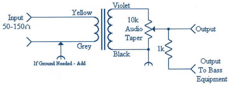
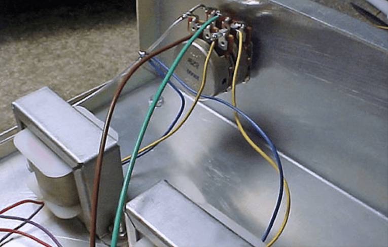
As the circuit diagram (Fig. 1) shows, the volume control wiper then goes to the output, and, if needed, to subwoofer outputs. The 1k resistor between these outputs serves to isolate any low-pass filter effects from the normal output. The circuit arrangement here ensures that the bandwidth will not change, no matter what volume level you use. It will not add or subtract inductance and capacity as other tapped ratio devices will. The output or source impedance of this device is within 10k or so.
It is best to keep the output to the amplifier interconnect capacity, around 50pF. If component isolation is necessary due to a ground loop, or if a hum develops while interconnecting the unit, you must insulate the input jacks from the case. Remove the ground from the input winding or jack. Grounds on the output and bass output must be common and cannot be isolated from each other.
Listening Notes
The audible result of this device is very interesting and different. One noticeable difference is the increase of amplitude range from low to high levels as well as increased detail. With a nonactive or passive means, amplification has an extremely accurate transfer characteristic result. A tube, as many people experience, will add its signature to the sound. Obviously, with no power supply, this design will have no power supply noise residue despite having gain. Normal listening level ranged from 11 to 2 o’clock on the control, so it has plenty of gain.
The silver secondary version of the transformer sounded the same as the all-copper, save for a slight but noticeable added softness or silky sound. Silver is more sensitive to flux variations than copper. It may reveal a very high number of harmonics. A nickel core low-level audio transformer seems to have an interesting resulting sound.
The first thing you notice is a wide swing in dynamic range very different from the original CD player op-amp output. The second is a clean, rich delivery of harmonics of strings and brass. Also note that it will bring out a poorly recorded CD. We know little at this point about why these effects are happening, but our theories are piling up.
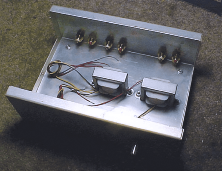
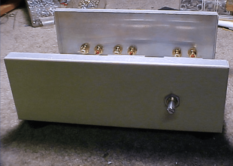
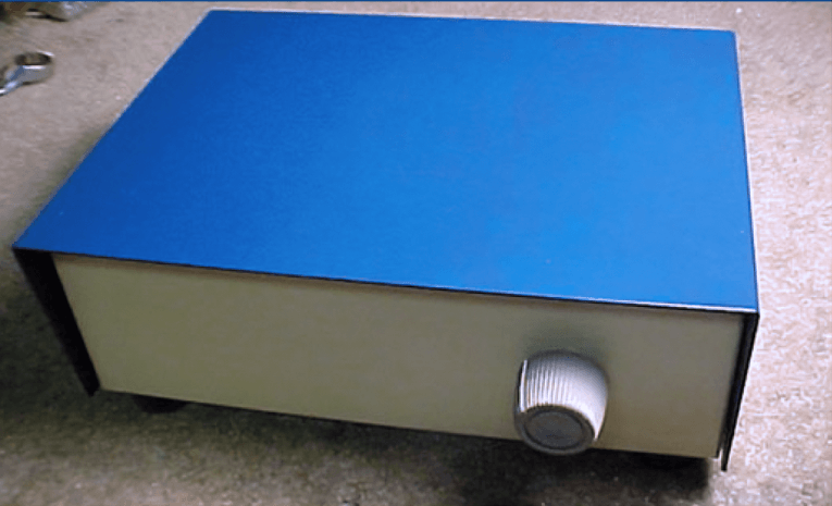
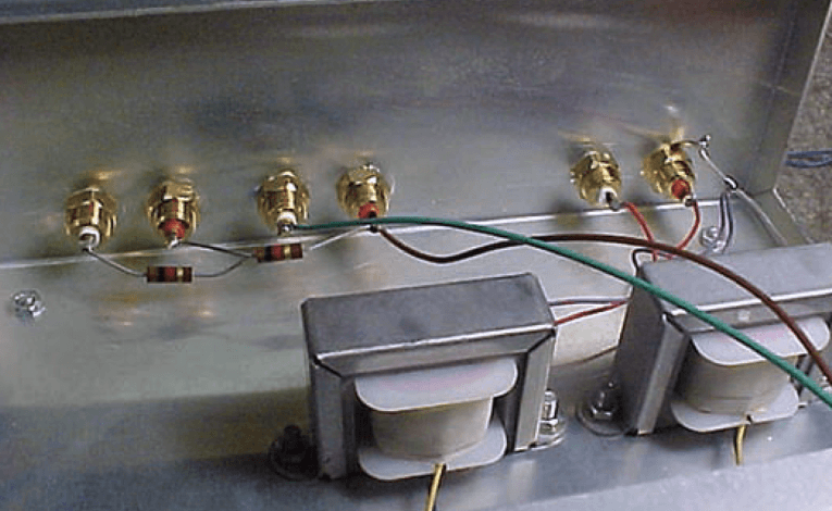
Construction
You should build the PVA with a steel chassis for best results. Steel will absorb stray magnetic fields from power transformers and chokes in other equipment located nearby. You can add switching to other inputs to the design in order to accommodate other music sources provided source output impedances are between 50 and 150Ω. Do not exceed 3V input or the nickel core will saturate and distortion will occur at low frequencies (patent applied for). aX
Parts List
2 PVE-3 Electra-Print transformer (nickel laminations with copper wire-$56 each) or PVA-3S Electra-Print transformer (nickel laminations with silver secondary-$250 each)
1 10k audio taper volume potentiometer or equivalent
1 7″ × 5″ × 2″ steel chassis with bottom plate or equivalent
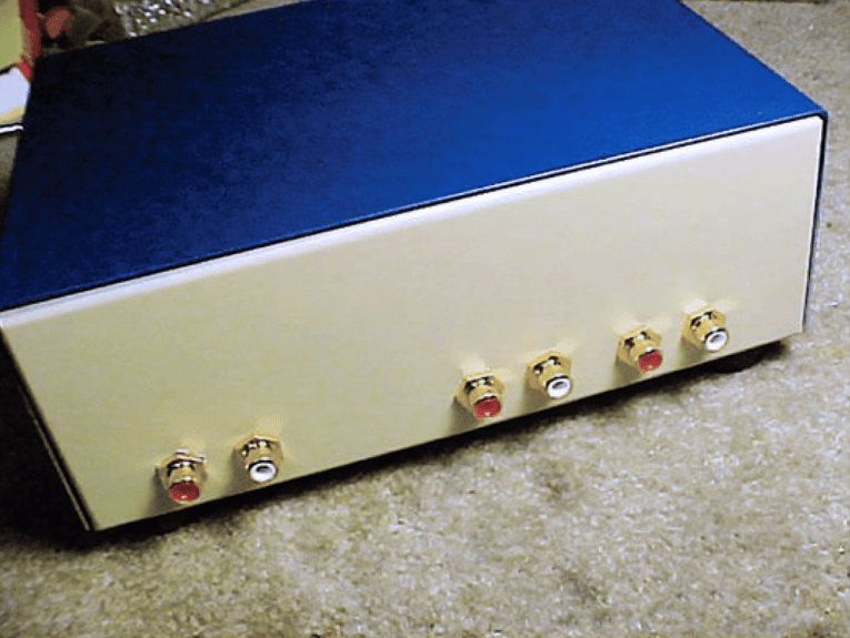
6 RCA jacks
2 1k 0.5W resistors
Transformers available from Electra-Print Audio
www.electra-print.com
This article was originally published in audioXpress, January 2005.