Key Goals
As I set out on this design, I began with a set of goals. First and foremost, I am both a serious amateur audiophile in pursuit of performance and an engineering pragmatist. I wanted a straightforward stereo source selector, monitor selector, volume control, and line amp, and not much more. This is not a home entertainment center/surround sound/video switcher/MP3/espresso machine—just good clean stereo. I wanted to achieve the following:
- Clean, long life, reliable source switching
- Electronically controlled, non-deteriorating volume control
- Impeccable sonic performance and low noise and crosstalk
My design includes the following features:
- Eight inputs—MM phono, Tuner, CD1, CD2, Tape1, Tape2, Aux1, Aux2
- Four record outputs with monitor select for CD2, Tape1, Tape2, Aux1
- Gold dual contact sealed relay source selection
- Front panel headphone output
- Front panel 1/8″ appearance of Aux1, for an iPod or similar device
- Optical encoder volume/balance control
- PIC microprocessor control
- Bypass-able bass and treble controls
- Mute
- Two sets of controlled outputs to amplifiers
- Ground plane main/audio PCB for low noise and crosstalk
- Two power switched 5V outputs to drive relay-controlled power strips for system components
Design Considerations
Beyond these features, there were three key design considerations. The first was the method of input selection—can I do this entirely solid-state? Short and simple, based on distortion performance and crosstalk, the answer is no.
I researched all the available analog switches, including those meant for high-end audio applications, as well as do-it-yourself discrete FET solutions, and nothing is adequate as far as crosstalk is concerned, primarily due to semiconductor parasitic capacitances. They also introduce a small amount of distortion due to Rdssat modulation. The next best, mechanical alternative was sealed relays. After an extensive search, I chose the Panasonic AGQ200 series, the 12V variety requiring relatively low coil currents, and featuring gold-plated bifurcated contacts. These should provide a life expectancy well in excess of most of us!
Second was the volume control—definitely not a potentiometer, and resistor ladder networks still involve mechanical contacts. I chose an optical encoder in conjunction with the highly respected Burr-Brown designed TI PGA2310 volume control chip. Given the cost of an optical encoder, and the desire for simplicity, I then decided to combine the volume and balance functions in one control, with a button to select between them, and LEDs to indicate the settings. Of course, once you choose the digital volume control, you already have one foot firmly stuck in the mud of the op amp/discrete design debate, which brings us to the third key design decision.
Op amps versus discrete. Like a good audiophile snob, I began this project firmly and faithfully committed to a discrete FET amplifier design approach, and scratched out multiple pages of J74- and K175–based phono and line stages, and prototyped them. They all worked quite nicely. (I’m sure some of you think it should have been 12AX7s!)
When I looked at PCB layout and put together a parts list, I realized what a load of discrete parts! What a forest this board is going to be! I decided to have a bake-off with an op amp alternative, especially because I already had working discrete FET prototypes. I went ahead and designed OPA2134-based phono and line stage alternatives, and ran them side by side with the FET prototypes. That raised the question of what kinds of tests to run.
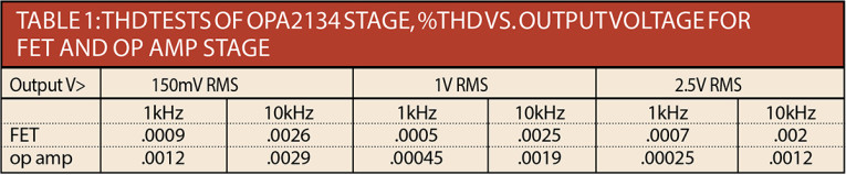
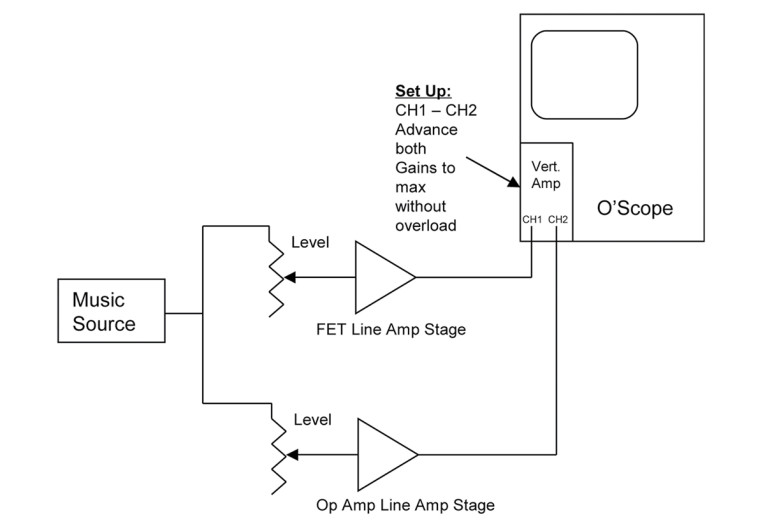
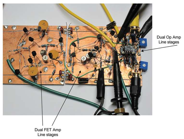
The first were standard THD measurements, with results in Table 1. While these look great for both designs, they don’t address dynamic performance, and I knew this was just not going to be sufficient in the world of discrete versus op amp mythology and never-ending controversy. From here, you can dive into IM, TIM, and various other esoteric measurements, but I wanted a more dynamic and convincing test, something that would resonate more with the ethereal golden ears hyperbolic comparative world, so I came up with the following (Fig. 1, Photo 1):
- Assume the discrete FET designs are golden—the standard of comparison—after all, they were adaptations of Borbely preamp/line stages that have appeared in print here. In any case, many consider and accept them as the “best effort” approach.
- Arrange the FET designs to be run in parallel with the op amp designs, fed by a common source, and provided with a precision input attenuation and output level matching capability.
- Feed the common input with real, dynamic, and varied music source material, not static signals.
- I fed the level matched outputs to my best Tektronix 2 channel oscilloscope amplifier, with one channel in the invert mode, and both in add mode, so that any amplitude or phase difference between the two inputs would show up clearly on the screen.
- Turn the scope amplifier channel gains up to the highest level they will handle without distortion or overload. I used a 7A26 plug-in on my 7904A scope, and this point was roughly at a gain of 80dB, which would make differential artifacts visible down to at least –90dB (~ 1/10 division). This can be done because the outstanding design of the 7B26 plug-in performs the invert/add functions far enough to the front end of the amplifiers that much of the gain appears after the subtraction. If you don’t believe this works, try it, and you will be amazed. It takes some effort to match the channel gains to get a null, and when they are slightly off, all that gain applied to a real difference will immediately make the scope display go off the screen!
- The result is a flat line if both input signals are identical, with any difference in the two showing up as blips or trace deviations on the otherwise flat scope trace.
- In addition to just looking at it (where you might miss something temporally), use the adjustable scope trigger level to “catch” any deviations between the two signals within, say, > -90dB.
- The final result? For the test comparison between the discrete FET line amp stage and the OPA2134 version, there was no discernible difference in output signals, for all the different music inputs tested, within a discernible amplitude of -90dB below the input levels. In other words, they produced—within a negligible error band—exactly the same output for the same input.
The unavoidable conclusion is that the op amp stages perform as well as the discrete FET alternatives, with real dynamic music signals, and greatly simplify the design. To seal the deal, I put the two prototype line amps in my system, between the CD player and amplifiers, with an A-B switch. The result, again, was that both sounded excellent, and indistinguishable.
The only thing left to do was to come to grips with the results and go ahead with the project!
Overview
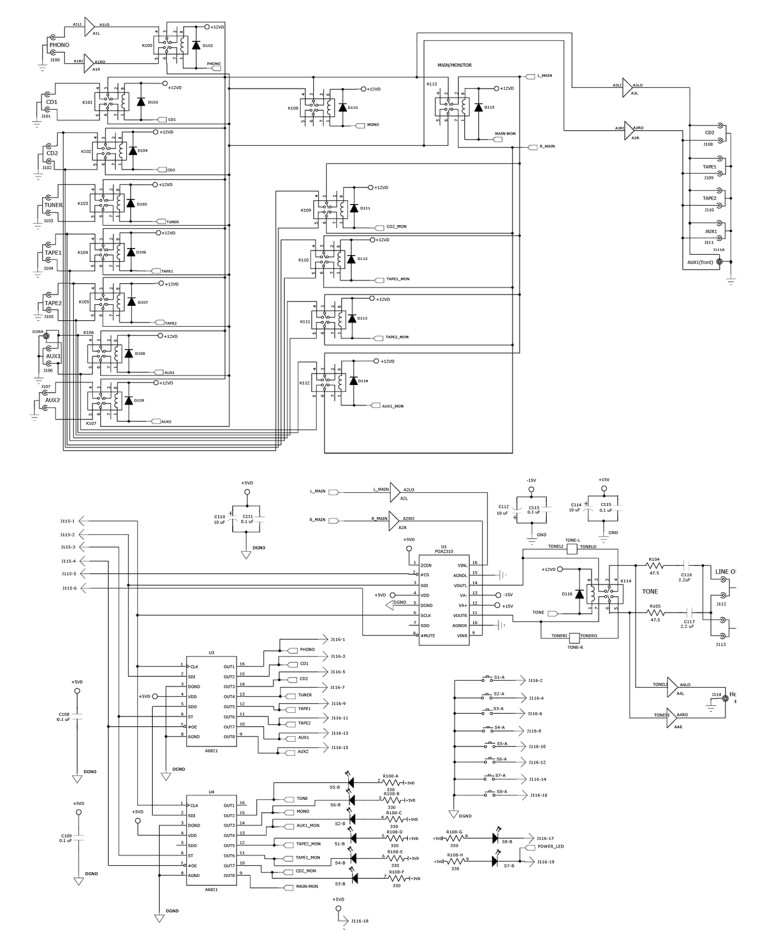
Figure 2 is a block diagram of the preamp. One of eight inputs is selected by a relay network. The phono input passes through the phono amp stage first to apply RIAA compensation and to bring it essentially to the same level as the other line level inputs. Four of the inputs also appear at the monitor select relays.

The left and right selector relay outputs may be bridged for mono by the mono relay, while the signals at this point are also fed to a pair of line buffers for the four record outputs. Following this, the main/monitor relay selects the signal to be passed on from the main inputs of the monitor selection. A pair of buffers feed the volume control chips, which are followed by the bypass-able tone controls. This, then, is also the controlled amplifier output. The pair of headphone amplifiers are also driven from this point.
The center of control is a PIC 16F877A microcontroller, which receives all of the switch inputs and the optical encoder input as parallel I/O, and controls LEDs, the volume control chip, and relay drive chips via an SPI serial interface. Power is provided by a toroidal transformer, accepting 120 or 240V input, and providing regulated ±15V for the analog circuits, and +12 and +5 for the digital circuits, with separate grounds.
Detailed Design
Input and monitor selection is performed by a set of 8 and 5, respectively, Panasonic AGQ20012 relays (Fig. 3). I chose these on the basis of their 1) small size, 2) low coil current requirement, 3) low resistance, gold-plated contacts, and 4) “duplex” bifurcated contacts, to ensure a long noise-free operating life. The same relays are used throughout for the Mono/Stereo, Monitor/Main, and tone control bypass switches.
All the relay coils are driven by a pair of Alegra A6821 SPI serial input parallel I/O drivers, U3 and U4—very convenient devices! All control push buttons are lighted with LEDs, which, in the case of those associated with relay functions, are also energized by the relay drivers.
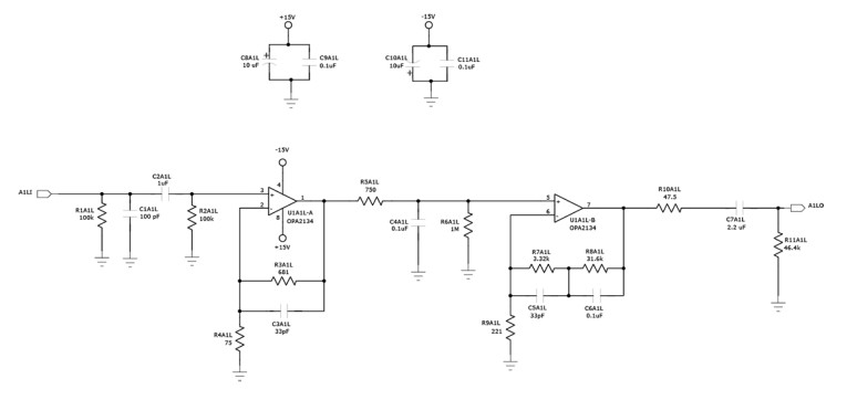
The phono preamp (Fig. 4) is the MM type, because I have no MC equipment. The MM design consists of a low impedance buffer stage driving a passive high-frequency rolloff, R5 and C4, followed by an active low-frequency boost stage, providing standard RIAA compensation.
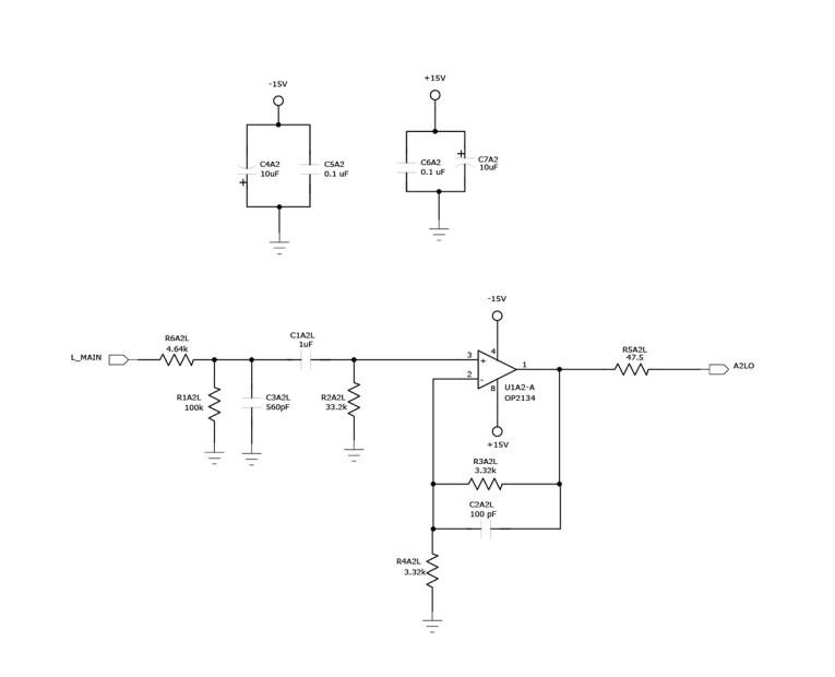
The record output buffer as well as the volume control chip input buffer are both simple ×2 gain stages (Fig. 5). Both are preceded with 75kHz low-pass and 10Hz high-pass filters, to remove low- and high-frequency input noise. The volume control chip requires a source impedance < 600Ω to meet its distortion specs—therefore, the buffer.
SPI serial input also controls the TI/Burr-Brown PGA2310 volume chip. More on how this is functionally used later, in the firmware section. Mute capability is also provided by the PGA2310.
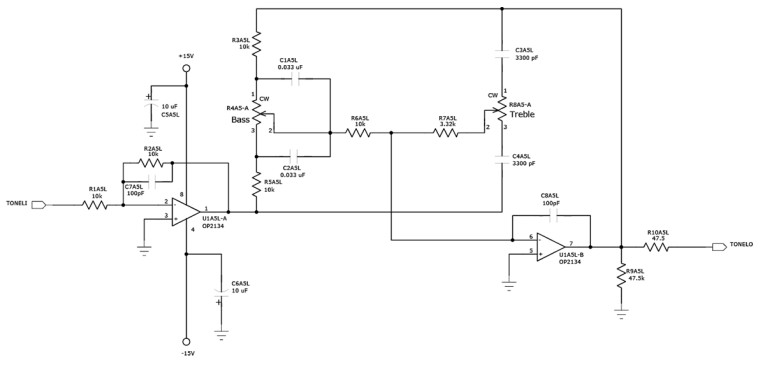
Output from the volume control goes to the pair of amplifier drive outputs, via the tone control bypass relay, which is normally in the bypass mode. The bass and treble tone control stage consists of a buffer, driving a double feedback loop Baxandall ±10dB boost/cut stage, with a 1kHz rollover frequency (Fig. 6).
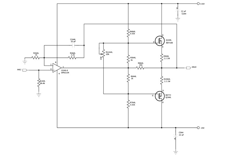
An op amp/FET power stage (Fig. 7) drives the headphone output, and is capable of providing several watts to speaker impedance loads, if desired. The power stage includes a bias adjustment, which you must perform as part of initial unit testing.
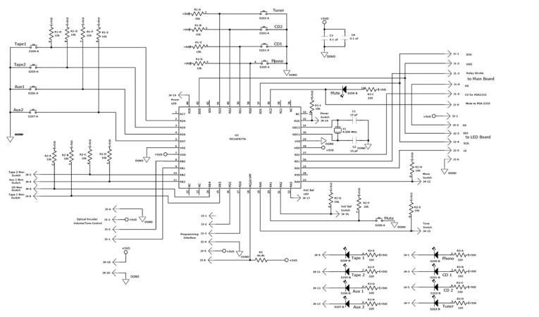
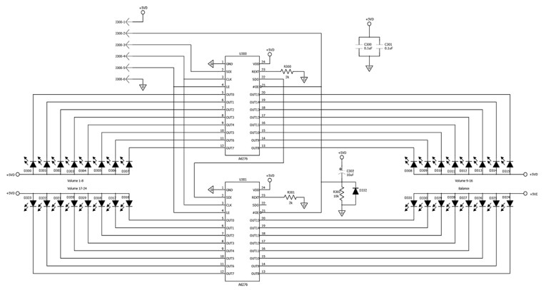
The controller (Fig. 8) is a PIC 16F877A, with internal program and user flash memory and SPI serial control. Select, monitor, and other push button inputs appear directly as parallel I/O. The optical encoder connects as a two-bit input. Volume position is indicated by a set of 24 LEDs arrayed around the encoder, while balance is depicted by a linear 4 + 4 left/right green/red LED display (Fig. 9). The firmware is described later, and is available for download, or programmed into a chip, as shown in the parts list.
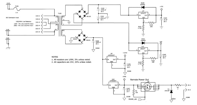
An Avel Lindberg toroidal power transformer feeds a pair of adjustable series regulators set for ±15V for the analog circuits, while the digital supplies are generated by fixed +5 and +12V regulators (Fig. 10). Adjustables are used for the analog supplies because they are quieter than the fixed variety. Grounds for the analog and digital supplies are kept separate, except for a single, well-chosen tie point, under the volume control chip. The power transformer provides windings for only one set of outputs. Add the digital supply windings to the transformer as described in the assembly guidelines.
When the preamp is plugged in, the power supplies and the controller are always on, and the power on/off function (power button) turns on the analog operation. In the off mode, all relays, and therefore input selects, are de-energized, and the volume is muted. In the on mode, input selections are recalled from EEPROM and applied, but volume always starts off at zero. The design includes a pair of power on/off controlled +5V outputs, which can control power to other system components. In my case, I added a relay to a power strip, into which my amps, CD players, and so on, are plugged, so the whole system comes up together. There is no need to flip an array of switches!
PCB Partition and Design
Circuitry is distributed over three boards. The main board houses all the analog circuitry, some of the control switches, and the very convenient Kobicon dual gold-plated RCA input and output jacks. The key features of the design here are a multilayer board that includes ground plane under analog signals, and very careful layout and power distribution to minimize crosstalk and noise.
The controller and input select switches are on the second board, a partition I chose for convenient physical layout of the switches and to keep the digital functionality separate. Finally, you mount the optical encoder and associated volume and balance indicating LEDs and their serial to parallel drive chips on a separate board, again to facilitate the mechanical design and minimize cabling. Boards are interconnected with ribbon cables.
Firmware Design and Functionality
The core is a four-state machine, driven by the de-bouncing states of button pushes. This is, in turn, embedded in a main loop that responds to optical encoder state changes. Each time around the loop, the state machine checks to see whether a button has been pushed, and if so, it is timed for de-bouncing, and then checked for release, before the handling routine for that button is entered. Then, the power button and optical encoder state are checked, and the unit’s operating condition is updated accordingly.
Optical encoder state changes result in increases or decreases of volume, or left/right balance adjustments if the control is in the “balance” mode. For more details including flowcharts for button functions, optical encoder reading, volume/balance adjustment, and volume and balance LED setting calculation and driving, check the website referenced in the parts list.
Some particulars of the firmware implementation that manifest themselves operationally are as follows:
- Input select, monitor, and mono/stereo switch states are retained in nonvolatile memory, and are reinstated after a power down/up cycle.
- Balance is returned to center, volume is set to zero, tone controls are bypassed, and mute is turned off after a power cycle.
- The very first time a unit is powered up, all inputs are de-selected.
- Monitor buttons toggle. When one is pressed repetitively, it toggles on and off. If one is on, and another is pressed, the new monitor is selected, and the previous one cancelled.
- The volume control chip inherently is adjustable over a gain range of +31.5dB to −95.5dB in 255 0.5dB steps. This is far too much gain on the top end, because my gain plan calls for approximately +9dB overall. The optical encoder volume generates an 8-bit word from 0 to 255, which the processing firmware translates to –95.5dB at the low end and +8dB for full volume.
Assembly Guidelines and Considerations
Probably the most important aspect of construction is surface mount soldering technique, a topic I will not cover in detail here, except to say that a high-quality small-tipped soldering iron, fine (< = .032″) solder, copper braid solder wick, a good magnifier, a bright work light, and steady hands are essential. I recommend a very careful inspection and review process before powering anything up. Table 2 is the parts list.
I leave parts choices and substitution up to you DIY readers, but I would not recommend substituting the following:
- The PGA2310 volume control chip
- The OPA2134 op amps, except if you know how to change compensation to maintain stability/compensation for an alternative
- The power FETs in the headphone amp
- The optical encoder, unless you chose one with the same encoding scheme and same number of transitions per rotation
- The poly/film capacitors, except with similar types—do not substitute ceramics or electrolytics for these
Areas where improvisation is encouraged include:
- The select push buttons. Their only requirement is a momentary contact and an associated LED. The ones shown are accommodated in the PCB layout, but others may be used and hand-wired.
- Input RCA jacks. The board is laid out for the particular Kobicon items, which are very convenient, but others may be hand-wired as your particular mechanical design accommodates.
The power transformer deserves some note. The digital power supplies require a separate winding, for which I found the addition of about 300 turns, 28ga, center tapped (150 + 150) to be about right. You can easily add these to the toroidal transformer specified. Alternatively, you can generate the digital supplies from the same AC winding that is used for the analog supplies, but this may compromise the hum/digital noise performance somewhat, although I have not tested this. You could also use a second transformer, or find/specify one that has the necessary windings to begin with.
I found installing all the surface-mount parts first the easiest approach to assembly. It allows the boards to lie flat, and also results in the least access interference for installing and soldering parts as you go along.
Before powering up the preamp, set both headphone amp bias adjustments to minimum bias. Then plug the preamp in and measure the voltage across R9A4R while adjusting R11A4R, until 60 to 80mV is reached, corresponding to a bias current of 30 to 40mA. Repeat for the left channel.
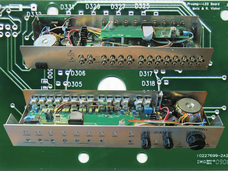
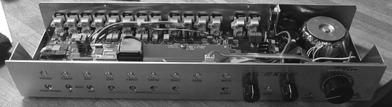
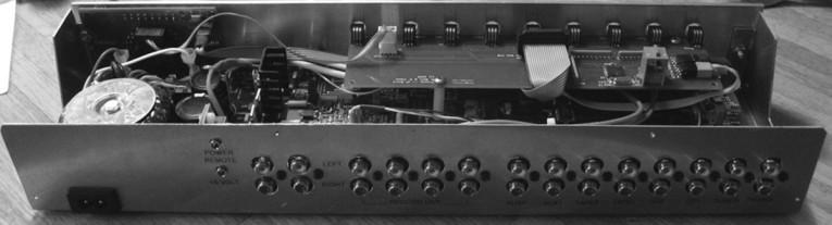
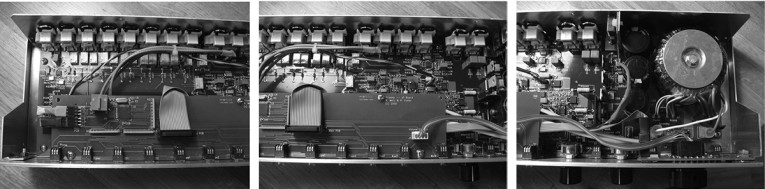
My enclosure is shown in Photos 5 and 6. It consists of two mating pieces of 0.050″ aluminum, one forming the bottom and back, the other the top, and a 1/8″ thick front panel. Photo 7 shows the assembled interior.
Performance
Performance data is shown in Table 3. The distortion figures, as you might suspect from the op amp datasheets, is respectable, although I put the greatest faith in the previously mentioned music comparison tests, and actual listening tests. The latter were performed with my HHB850 CD player, a pair of my designed FET power amps, and a pair of my designed speakers, employing KEF drivers. The results were exceptionally pleasing, but to claim any more here would be self-serving.
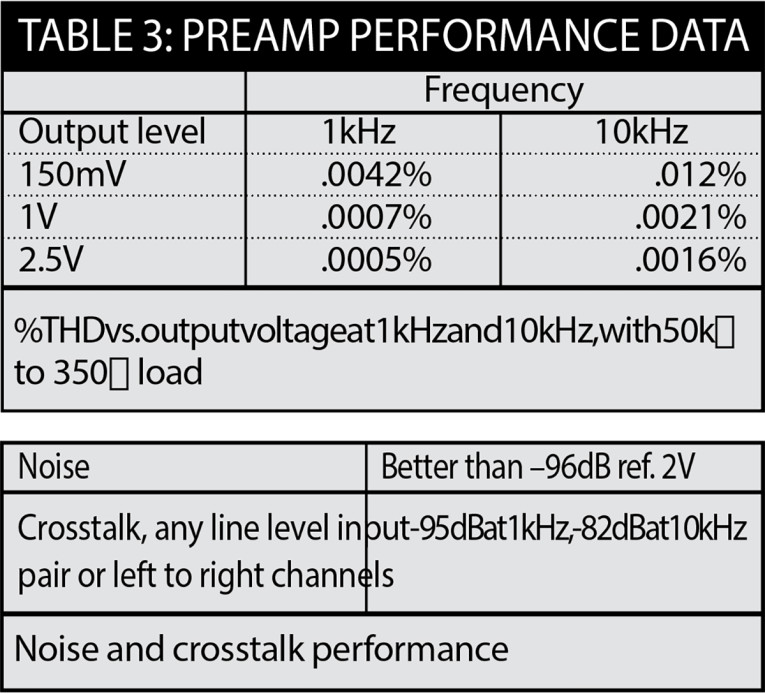
The ground plane main board appears to also have paid off, given the noise and crosstalk figures. aX
Sources
Mouser — www.mouser.com
Digi-Key — www.DigiKey.com
Avel Lindberg — www.avellindberg.com
See also audioXpress Supplementary Material page for PC board layout and more.
Author's website for this project: www.a-and-t-labs.com/K12_Preamp/index.htm
This article was originally published in audioXpress, August 2010.
 About the Author
Reinhard Metz has B.S. and M.S. degrees in Electrical engineering from the Illinois Institute of Technology and The University of Illinois, respectively. He has worked over 20 years as an engineer and manager at Bell Laboratories, AT&T, and Lucent technologies. In 2001, he left Lucent and started an engineering/consulting business specializing in circuit design, particularly power circuits. The business also provides technical expert services for intellectual property legal cases. Throughout his career, Reinhard has maintained an avid audio hobby, including many of his own designs. He has multiple patents granted.