Placing a solid-state preamp between the switched line-level audio inputs and the old tuner and power amplifier would be acoustically clean, but building a tube preamp always seemed more appealing. The effort involved in constructing all the mechanicals for a stereo tube preamp, combined with the fact that this was not a pressing problem, kept the project off my priority list for years.
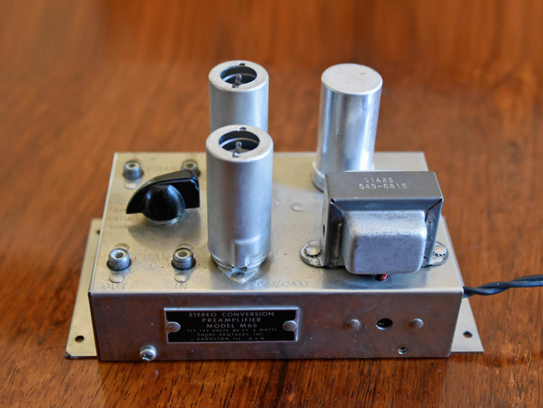
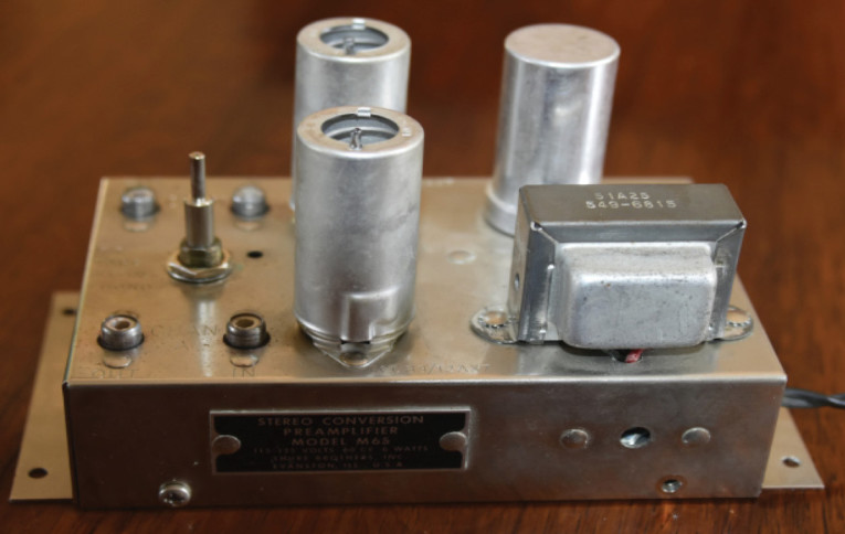
Eventually, I realized that I had a flea market find that could supply the mechanicals. It was a small, 1960s Shure Brothers stereo preamplifier (Model 65) that had been in the closet for decades (see Photo 1). Mechanically, it was beautiful, but the channel gain was extremely high. However, the little preamp had a chromed case with shielded tubes, audio connectors as well as a small B+ and heater transformer built in. It would be a perfect mechanical platform for the preamp I wanted.
The new preamp design would be relatively simple because it was receiving a low-impedance signal and driving a high-impedance load. The old Shure preamp used two 12AX7 dual-triode tubes (one for each stereo channel). The schematic for the original Model 65 preamp and datasheets for the 12AX7 tubes are easy to find online. In Shure’s original preamp, each audio channel was a series pair of common-cathode amplifiers (because the design needed lots of gain). I wanted very little gain, so an obvious architecture for the new preamp was a common-cathode amplifier (for gain) followed by a cathode-follower stage (to lower the output impedance).
The Creative Process
Because common-cathode amplifiers produce much more gain than this application needed, ironically, it was necessary to reduce the level of the input signal before sending it into the preamp. This initial gain reduction would be accomplished by a potentiometer at the input. This volume knob could occupy the spot originally filled by the Shure amplifier’s channel-select switch.
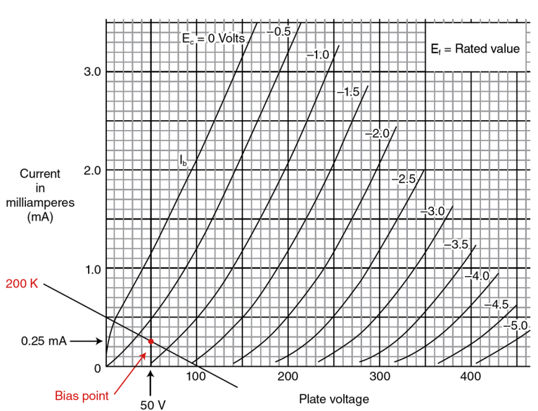
The 1967 Shure schematic shows that B+ is an unregulated 100 V. I wanted a nominal plate voltage of half of B+ to maximize headroom. Since the power transformer is small, I didn’t want to exceed 0.75 mA per channel (the original circuit used 0.5 mA per channel). I would need to save most of this 0.75 mA for the second (output) stage, so I allocated 0.25 mA to the first amplifier.
After locating an operating point of 0.25 mA and 50 V on the “Average Plate Characteristics” graph in the tube datasheet (see Figure 1), it was obvious that a 200 kΩ load line connected nicely with the maximum plate voltage (B+) of 100 V. Since this first stage will be feeding the high-impedance grid of the cathode-follower second stage, the external load on the first-stage amplifier will be primarily its 200 kΩ plate resistor. A 12AX7 datasheet gives the following typical tube characteristics:
mu (tube gain) = 100
ra (internal plate resistance) = 80 kΩ
So, the low frequency gain should be approximately:
Av = mu (Rload)/(Rload +ra)
Substituting 80 kΩ for ra, 100 for mu, and 200 kΩ for Rload yields an approximate low-frequency gain of 70. Clearly, the input gain-reduction potentiometer was necessary, and in fact, we need to add a series resistor on top of the potentiometer to allow it to nominally work near the middle of its range at our desired gain of ×2. Because this resistor calculates out to be 100 kΩ for a gain of ×2 (33 kΩ for a gain of ×5) at the potentiometer midpoint, we will need to bypass it with a small capacitor. Stray capacitance, will create a high-frequency pole that will roll off the amplifier’s high-frequency response. I’d like to add a zero with this small capacitor at that pole frequency to extend the first-stage frequency response. My plan was to measure the amplifier’s frequency response without this capacitor, determine the high-frequency pole, then calculate and add the capacitor.
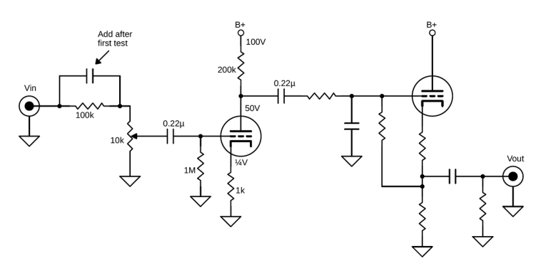
To finish the first-stage design, I somewhat arbitrarily selected a 1 MΩ grid leak resistor and a 0.22 µF input-coupling capacitor. This combination should yield a high-pass filter (low-frequency zero) at about 4 Hz. Figure 2 shows what the design concept looked like at this point.
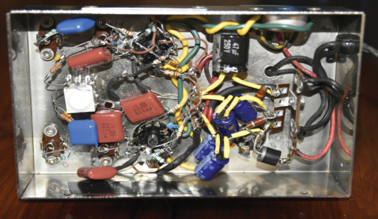
It was now time to build and test one of the common-cathode stages. But first, I needed to remove the old circuit, leaving the B+ and heater portions. Photo 2 shows the enclosure with the old circuit removed but the power section retained. The right side is the power section. Many years ago I had replaced the old wax and paper capacitors.
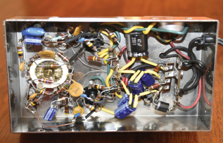
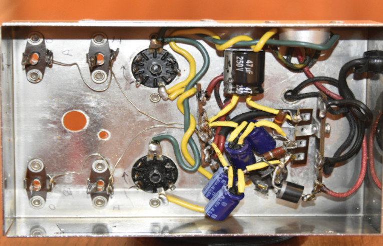
Photo 2: The original enclosure is shown (a) and with the original signal-path circuit removed (b). The power section is on the right side of the enclosure.
Testing the A-side first stage revealed clean performance. The plate and cathode voltages were as predicted. With the 10 kΩ input potentiometer set at its midpoint the gain was flat at a factor of 2 (6 dB). There was one low-frequency zero (as we expected), there was one pole at about 4 kHz and no other poles or zeros out to 100 kHz.
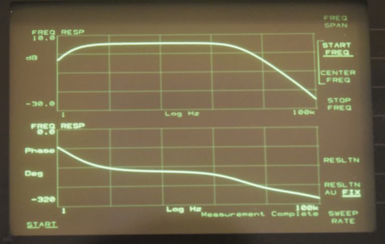
Now we could determine the capacitor value to place a zero at 4 kHz. The calculated value was 400 pF. I installed a 470 pF capacitor, and the resulting frequency response is shown in Figure 3. These voltage transfer functions were measured using a Hewlett Packard 3562A Dynamic Signal Analyzer, but they can be plotted manually by recording the output/input voltage ratio at a number of frequencies. You can see the gain rising to the low-frequency zero, flattening off nicely through the audio range, and then rolling off with the added high-frequency pole. The first stage looked good.
Second Stage: Cathode-Follower Amplifier
The second stage is somewhat of an upside down version of the first stage. We want a 0.5 mA plate current. Using the calculation of 100 V divided by 0.5 mA yielded a cathode resistance of about 200 kΩ. So now we have an almost complete design. Figure 4 shows the revised schematics at this point.

The only component remaining to be sized is the low-pass filter capacitor at the second grid. The cathode-follower will add some high-frequency dynamics to the transfer function, and the low-pass filter (aka a dominant pole) created by the yet-to-be-determined capacitor is intended to roll off the transfer function at about 20 kHz. This should eliminate any high-frequency shenanigans. An added 330 pF capacitor resulted in a very nice looking transfer function (see Figure 5).
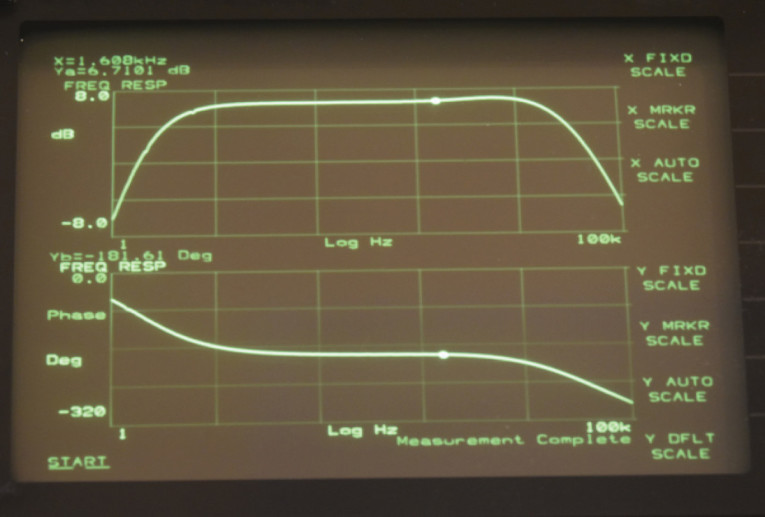
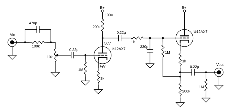
Figure 6 shows the final schematic. Photo 3 shows the completed amplifier. Photo 4 shows the inside of the amplifier with a dual (but not ganged) potentiometer replacing the original switch.
The Result
This little preamplifier project looks great and I kept the original Shure Brothers nameplate. Finally, and most importantly, the little amplifier sounds nice. aX

This article was originally published in audioXpress, May 2020.
 About the Author
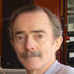
Bill Reeve has a life-long interest in electrical and mechanical design. He has Masters of Science degrees in Electrical Engineering, Mechanical Engineering and Geological Engineering. He worked first as a consulting geologist, then spent 28 years at Lockheed Martin as a program director managing the development of NASA satellites and space instruments, in addition to serving as an Engineering Director at the DeWalt Industrial Tool company. Currently, Bill is a Technical Program Manager at Google.