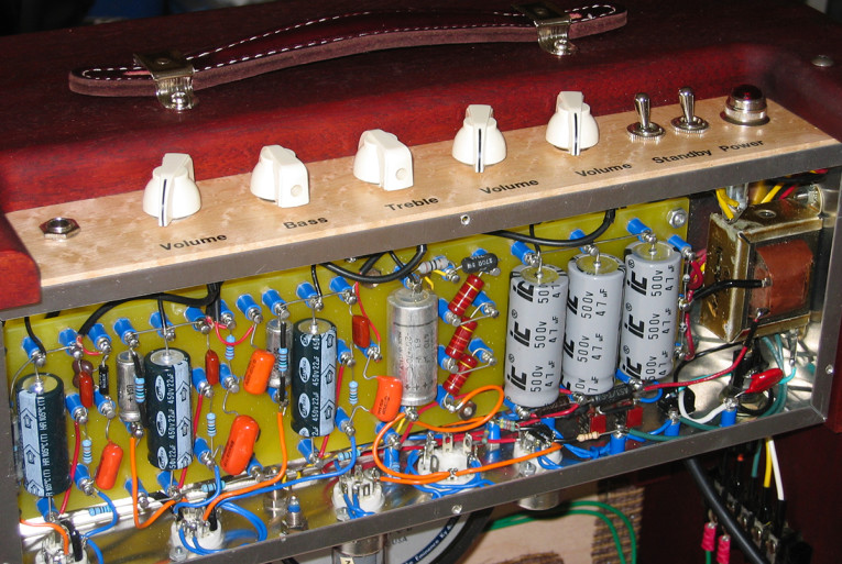
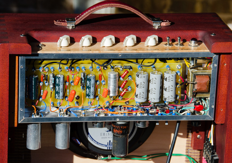
In 1992, Kirk Elliott shared his take on the design, transforming the stock Champ into a quieter, safer, and more reliable studio amplifier. He explained how to add a third gain stage and greatly improve the power supplies and grounding in “The Remaking of a Champ,” published in Glass Audio, the predecessor to audioXpress. Inspired by Elliott’s article I made my own Champ clone in 2003 (see Photo 1). I recommend reading Elliott’s original article as a companion to this one. The article is now available online (see Resources).

The Remade Champ Design
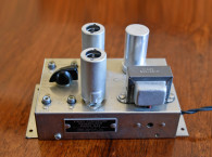
I followed Elliott’s design with the added novelty of a provision to easily try different output tubes. I wired three output tube sockets in parallel, one of which is populated at any given time. The octal socket can accommodate the original 6V6 or alternatively a 6L6 or 6F6 (7AC pinout). A 9 pin miniature socket takes a 6GK6 pentode (9GK pinout), and a second 9 pin miniature socket is for a dual triode 12BH7A (9A pinout) with the two sections paralleled. The pentodes can be switched to triode mode and B+ can be operated at two levels (see Photo 2). This enables experimentation in the search for that perfect sound.
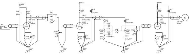
I built the preamp stages directly from Elliott’s design (see Figure 1), which was listed as Figure 6 in his original article. Relative to a stock Champ, there is an additional gain stage (V602a in the schematic), different equalization, and no feedback from the output stage. Three independent volume controls (the last one shown in the output stage schematic) let you adjust which stages distort and how much.
I have noticed some tendency to radio frequency interference (RFI) pickup and think that a grid stopper or ferrite bead on the grid lead close to the input tube would be a useful improvement.
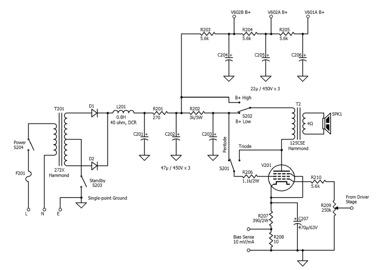
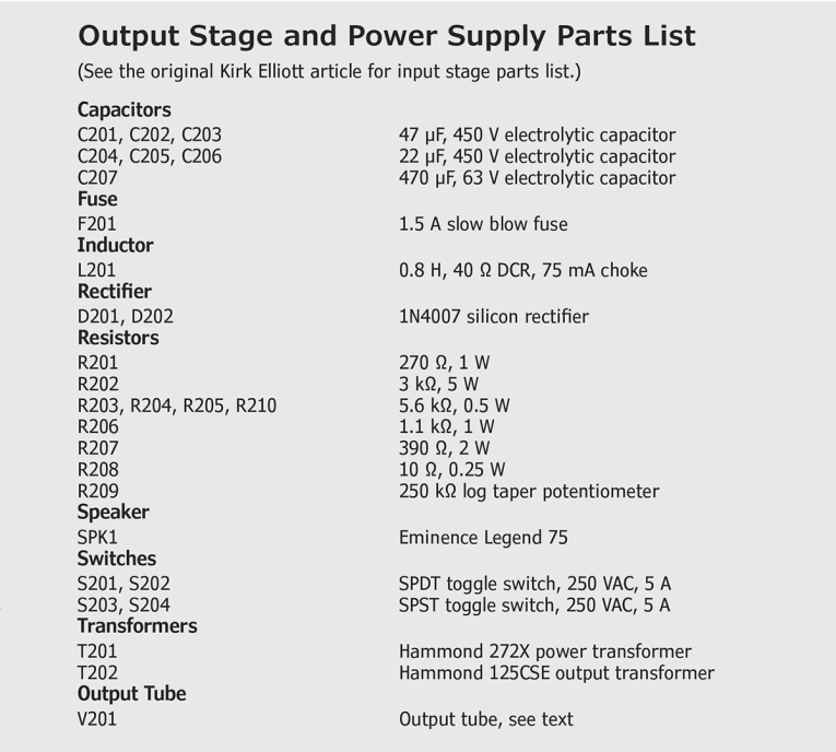
Power Supply and Output Stage
The power supply and output stage are shown in Figure 2. The B+ supply is a center-tapped fullwave design with solid-state rectifiers and a choke input. The divider string for the preamp stages is identical to Elliott’s, and provides isolation between stages to prevent “motorboating”—low-frequency oscillation caused by positive feedback between stages. The choke input reduces voltage to the filter capacitors. If you modify the power supply, ensure that the capacitors have adequate voltage rating, or use two series connected capacitors with balancing resistors, as Elliott did.
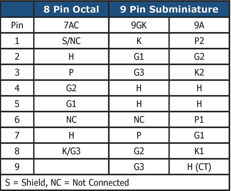
As in the original Champ, the output stage is a singled-ended pentode with self-bias provided by a bypassed cathode resistor. A switch is added to operate pentodes in triode mode by connecting the screen grid to the plate. The three tube sockets are wired in parallel with each tube having its own grid stopper resistor mounted as close as possible to the socket. Use separate grid stoppers for each half of the 12BH7A (see Photo 3). The grid stopper is larger than typical (5kΩ) to limit grid current during overdrive. Pinouts for the three socket types are shown in Table 1.
In the “Pentode” “High” setting the design becomes similar to Elliott’s. He found that many output tube reliability problems were due to excessive screen current during heavy overdrive and added 25kΩ in series with the screen supply. I used a somewhat smaller (3kΩ + 1.1kΩ) series resistance, which also allowed me to implement the high/low B+ arrangement. So far, I have not had problems. In the low setting the 3kΩ resistor drops the B+ from 400V down to the 250 to 300V range depending on the current drawn from the particular output tube.
It will also increase “sag”—the tendency of a tube amplifier’s B+ to drop during periods of heavy drive. As with distortion and microphonic feedback, sag is one of the characteristics that creates desirable tube guitar amplifier sound, yet would be considered a defect in an audio enthusiast’s amplifier. The 3kΩ resistor needs to be rated at least 5W. Output stage bias becomes a bit of a compromise across the variety of tube and B+ choices. The cathode bias resistor is built up from series connected resistors to make it easier to tweak, and a 10Ω sense resistor (10 mV/mA) is connected to externally accessible test points to make bias measurement easier. I ended up using a 400Ω cathode resistor, bypassed with 470μF.
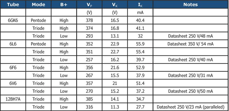
Table 2 shows DC bias conditions for a variety of output stage configurations. Some sample datasheet recommendations from the RCA RC-26 Tube Manual (see Resources) are shown and are a reasonably good fit to this design. Consult tube datasheets before playing with other combinations. Make sure to power down the amplifier prior to changing the tubes or the tube mode/voltage switches.
The output transformer is a Hammond 125CSE, rated at 8W and 60mA DC plate current. A Hammond 272X is used for the power supply. Elliott used a regulated DC supply for the filaments to reduce noise. I opted to stick with simpler AC filaments and, in hindsight, wished I had followed his advice. There is a slight AC hum present in the amplifier that I could never completely eliminate.
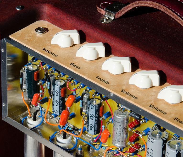
The Cabinet
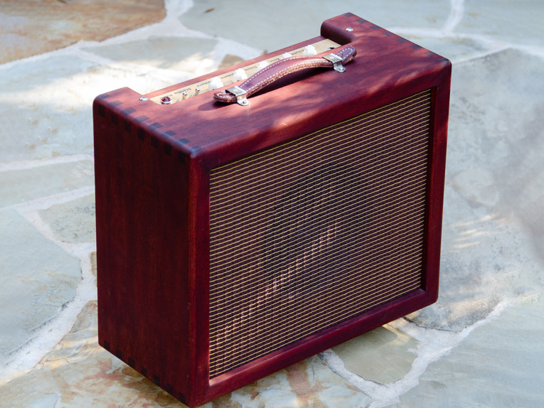
The mechanical layout is typical of Fender amplifiers, but with more exotic materials than normal. The case is mahogany, stained, and finger jointed. The bezel is birdseye maple with “chicken head” style knobs (see Photo 4). For the speaker, I used an 8” Eminence Legend 75. Internally, the bulk of the components are mounted on a 0.125" thick, 3" × 11" FR4 tag board. I used single-point grounding. The chassis is aluminum to eliminate electromagnetic coupling from the power transformer and the choke. Tube shields for the preamp stages also help eliminate noise. Don’t use shields on the power tubes since they severely limit cooling.
With the versatility of three gain stages, independent volume controls, and a variety of tube and output stage choices, this amplifier can produce a variety of tones (see Photo 5). Boutique single-ended studio amplifiers are very popular. Elliott showed us how to get there 23 years ago, and his design still makes a great foundation for modifying a classic Champ or building one from scratch as I did. aX
This article was originally published in audioXpress, January 2016.
Resources
K. Elliott, “The Remaking of a Champ,” Glass Audio, Volume 4, Number 2, 1992,
www.audioxpress.com/article/Glass-Audio-Vault-The-Remaking-of-a-ChampRCA, Receiving Tube Manual RC-26, 1968.
 About the Author
Mark Driedger was born in Canada in 1963. He has an MSc in electrical engineering from the University of Waterloo. Mark has worked in the telecom industry for 27 years in various technical, business, and executive roles. He is currently COO for Procera Networks and lives in Dallas, TX. He has been experimenting with tube audio since 1980. His other passions include his wife and two children, woodworking, and the guitar.