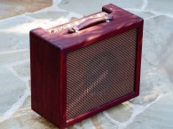
 The Fender Champion was introduced in 1948 and was marketed as a practice amp for music students. The design was pretty basic: one 6SJ7 pentode preamp, a volume pot, and a single 6V6 beam power tube driving an 8” Jensen speaker. The name was later shortened to “Champ,” and the 6SJ7 was eventually replaced with the miniature dual 12AX7A triode. Subsequent designs saw the addition of such refinements as tone controls and negative feedback, but the single 6V6 and the 8” speaker remained until the amp was discontinued in the 1970s.
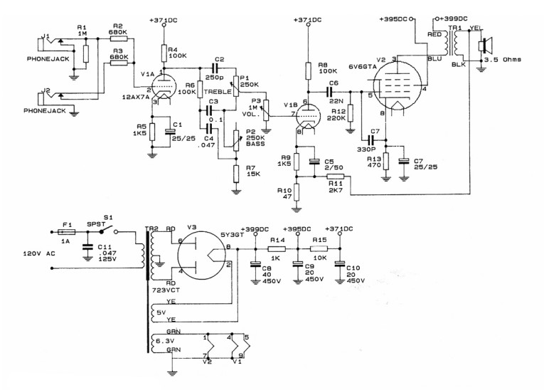
Figure 1 shows the original schematic of the Champ that I modified. The unit belongs to a musician friend of mine, and one day we were discussing ways of making the little Champ more suitable for studio work. I offered that an additional preamp stage would be a cinch to install, and would give him more overdrive and sustain when he needed it. He gave me the go-ahead to do the work.
Design Objective
Well, what started out as an easy mod turned into a substantial rethinking of the whole amp. Simply adding another preamp tube revealed some significant limitations of the original Champ design and construction. The modified amp motorboated. It oscillated at a bewildering array of frequencies - anywhere from about 8kHz to 1.5MHz, depending on the control settings.
Sometimes it motorboated and oscillated at the same time, spitting out rhythmic chirps of high-frequency unpleasantness. It hummed unmercifully, especially at high gain. When driven hard, the output stage sounded thin and weak. There were some reliability problems - at maximum volume, the sound cut in and out randomly, accompanied by bright flashes of orange and blue light from the 6V6. Two 6V6s eventually perished in this manner.
Through careful attention to grounding, shielding, layout, and power supply design, I managed to tame the oscillation and hum. I overcame the output stage problems by selecting a better sounding transformer and more robust tube, and by incorporating some simple circuitry to keep the tube operating within its ratings.
I formulated some ground rules for the project, too. The design objective was to build a small, rugged amp for studio work: highly reliable, extremely quiet, capable of a wide range of tonality, and responsive to the touch of a good player. It all had to fit into the original Champ chassis and cabinet, and had to retain the spirit of the Champ design: simple tube circuits and single-ended output. The ideas presented here are by no means the last work on guitar amps. My hope is simply to show you how tubes are used in the creation of music, and to encourage you to try some of this stuff yourself.

Small Amps in the Studio
Why do we use guitar amps in the studio? After all, the electric guitar puts out an electrical signal. Surely there is a way of getting this signal to tape without the bother of amplifiers, speakers, and microphones.
There is, and it’s called the “direct box” or DI (for direct injection). The simplest DIs are special transformers that perform impedance and level matching to interface the guitar pickup to the recording console’s microphone preamp input. Since the recording chain is designed with low distortion and flat frequency in mind, what we get from this process is essentially the unadulterated sound of the guitar pickup. (If you’ve got an electric guitar and a 1/4” to RCA adapter cable, you can get an idea of what this sounds like by plugging your guitar into an aux or other line level input of your hi-fi system and turning up the volume).
Plugging into a tube guitar amp and then miking the speaker is a different story. The amp adds tonal coloration and can be made to generate varying amounts of distortion. Even the selection and placement of mikes can have a truly dramatic effect. The result is richer and more musical than the sound of raw DI sound. The DI certainly has applications, but it’s the tube amp that makes the electric guitar sing.
Fruitful Upgrades
Small amps aren’t used that much on stage, simply because they’re not loud enough to compete with the rest of the racket. In the studio, close-miking, multitracking, and the use of headphones for performers have allowed engineers and musicians to exploit the unique sonic signatures of little amps like the Champ.
Sometimes a cheap 10W amp can be made to sound like walls of Marshalls filling a hockey arena. Purism yields to practicality in a pop recording session. The client is looking for a sound. You do what you have to do to get it. Small amps become another weapon in your arsenal.
By now it should be clear that upgrading a guitar amp for studio work is not quite the same as upgrading a hi-fi system. We are dealing with a piece of gear whose whole raison d’être is to color the sound, so typical audiophile mods aimed at preserving waveform integrity are going to be off target. Amplifier harmonic distortion is actually considered beneficial, since it adds character to the guitar. Loudspeakers generally acclaimed as good guitar amp speakers have very ragged-looking response curves with little top end. The frequency response of the amp itself is not flat, but rather works with that of the speaker to produce an overall musical sound. A lot of modern guitar sounds require that the output stage be massively overdriven, a situation which can continue in the studio for hours on end, day after day, creating special demands on reliability that just don’t arise in the high-fidelity world.
Nevertheless, many of the concepts and instincts we have developed regarding audio modifications will serve quite well. Power supply upgrades are as fruitful here as elsewhere, although stiff regulation of the audio stages is neither necessary nor desirable. Low noise, stability, and hum-free operation are very important. So is the use of high quality active and passive components.
Heater Supply
Figure 2 shows the block diagram of the modified Champ. We can get over 100dB of voltage gain from the grid of the first preamp tube to the plate of the power tube, so any tiny noise at the low level stages can prove disastrous at the output. It’s very important to realize that while the full gain of the amplifier is applied to any input-referred noise or hum, this is not necessarily so with signal. Clipping will typically limit signal voltage excursions at high gain, making signal-to-noise considerations both more complex and more demanding than they are with linear amplifiers.
The stock Champ used 6.3V AC for the heaters, grounding one side of the 6.3V winding to the chassis and using the chassis as a return path for heater currents, a path shared by audio signals. There was considerable coupling of 60-cycle hum into the signal path, a phenomenon accentuated when I initially added another preamp stage.
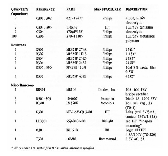
So I opted for a fully regulated heater supply, set to the rated 6.3V DC for the preamp tubes and the power tube. The circuit, shown in Fig.3, is pretty straightforward, but there are a couple of interesting points. The supply has to furnish current to three 12AX7A sections (0.15A each), the 6L6GC (0.9A), the indicator LED (20mA), and the relay (30mA), for a total of 1.4A. The original Champ 6.3V winding only had to supply two 12AX7A sections and the 6V6GTA (0.45A), which adds up to 0.75A. Unsure of the current rating of this winding, I elected to install a brand new 8V 3A transformer. The LM350K regulator is essentially a 3A version of the LM317. I mounted it to the outside of the chassis with a mica washer and some thermal compound to heatsink it.
The relatively high value (470µF) for the adjustment pin bypass capacitor C304 gives the supply a bit of a start-up ramp. The timing circuit associated with K301 delays the onset of the B+ while the heaters warm up. Ripple on the 6.3V DC supply is much less than 1mV p-p, effectively eliminating the heaters as a source of hum. The chassis symbol in Fig.5 indicates the star ground point of the amp, a ground tab on the large B+ Mallory filter can C503. All audio grounds are tied to this tab via separate green wires, and a green wire references the 6.3V DC supply to this same point. More about this later.
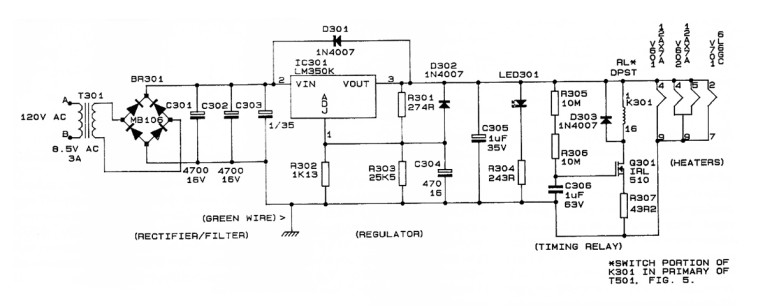
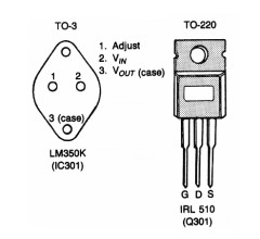
Plate Supply
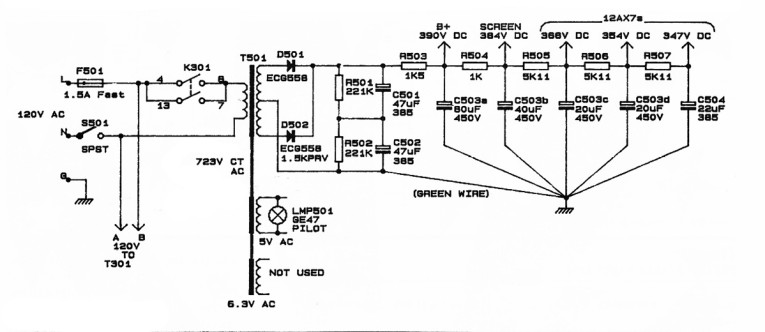
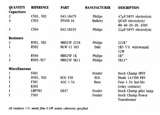
A push/pull output stage benefits from hum cancellation. Not so with a single-ended output. B+ hum can easily find its way to the speaker, which it does in a stock Champ. As a remedy, I replaced the venerable 5Y3GT tube rectifier with a solid-state rectifier, followed by an additional RC filter to drop the voltage back down, and replaced the stock Mallory can with a larger quad unit (Fig.5). The result is a B+ ripple voltage of only 100mV p-p, compared with 6.5V p-p on the stock Champ. Any B+ induced hum is virtually eliminated in the speaker.
The ECG558, rated at 1500 PRV and 1A, provides a neat answer to the high-voltage rectifier question. (A diode in a full-wave 723A AC ct receiver circuit needs a rating of 723V x √2 = 1022 PRV, so using an 1N4007 would be pushing it.) Another good possibility is the ECG525, rated at 2000 PRV and 1A.
R505, R506, and R507 decouple the low level stages along with C503c, C503d, and C504. In a stock Champ, the preamp stages are decoupled from the power stage, but not from each other. I’ll talk about decoupling some more when the issue of stability comes up.
As for grounding, the metal can C503 is soldered directly to the chassis, and the negative terminal of C504 is soldered right to the start ground point, a solder tab on C503 (as mentioned earlier). C501 and C502, along with R501 and R501, are mounted on perfboard.
The center tap of transformer T501 connects to the negative terminal of C502, and a separate green wire is run from the negative terminal of C502 to the start ground point on C503. These precautions keep ripple return currents out of signal ground leads.
Death Switch
The treatment of mains voltage entry on many old amps presents a possible shock hazard to the musician. The metal strings on most guitars are connected to signal ground, and when the player plugs his guitar into the amp and touches the strings, his body really assumes the potential of the amp chassis. If the amp uses a two-prong AC plug, there is clearly the possibility that an internal malfunction could put a lethal voltage on the chassis and therefore onto the player’s body. If the player then touches another metal surface in the studio at ground potential, such as a mike casing, a metal panel, or the properly grounded metal chassis of another piece of gear, he’s zapped. Worse, older amps using two prongers sport a “death” switch that selects which side of the mains is connected, directly or via a capacitor, to chassis!
If your amp uses a two-prong AC cord, tear it out and replace it with a three-wire cable, connecting the green wire directly to the chassis. If there are any so-called “ground” switches, or any capacitors across the mains or from either side of the mains to the chassis, remove and destroy these items. Connect the live and neutral to the power transformers via the fuse F501, relay K301, and switch SW501 as shown in Fig.5.
This is not just theory - I’ve seen guys get some very nasty shocks in the studio from old amps with two-prong AC cords and so-called “ground” switches. Take heed and live a long life!
Preamp Stages
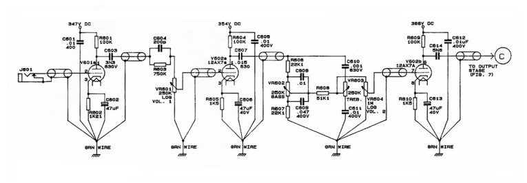
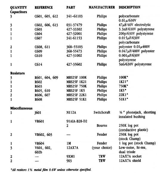
Three simple 12AX7A gain stages combine with some fixed and variable low- and high-frequency equalization to form the low-level stages. The variable EQ consists of standard bass and treble controls. The fixed high- and low-frequency EQ curves are chosen so that the range of the tone controls makes musical sense in the context of the overall amp sound.
The fixed low frequency EQ comes from the -3dB rolloffs determined by C603, C607, and C614, namely 50Hz, 40Hz, and 115Hz, respectively. This is exactly how the textbooks tell you not to build a three-pole high-pass filter, but in this case, the gradual attenuation of bass frequencies works well. Fixed high frequency EQ, generated by R603, C604, and VR601, comes in the form of a shelving curve or “treble boost,” with corner frequencies of 1kHz and 4kHz and an ultimate boost of about 12dB. There’s much room for creativity here, and the results of the process - an iterative one involving estimation, calculation, componente selection, and audition - are finally judged by the ear.
The chassis symbols in Fig.6, as elsewhere, refer to the start ground point. Each stage and each volume control is tied to this point via a separate green wire. We’ll discuss this in more detail when we address the stability problem.
Output Stage
The choice of output tube, transformer, and speaker will determine to a large extent the amplifier’s sound. The transformer is the tricky part, since there aren’t all that many tube output transformers available anymore - especially ones designed for single-plate operation. Because of the net core magnetization inherent in a single-ended output, trying to adapt a push/pull transformer to this type of circuit usually compromises low-frequency performance.
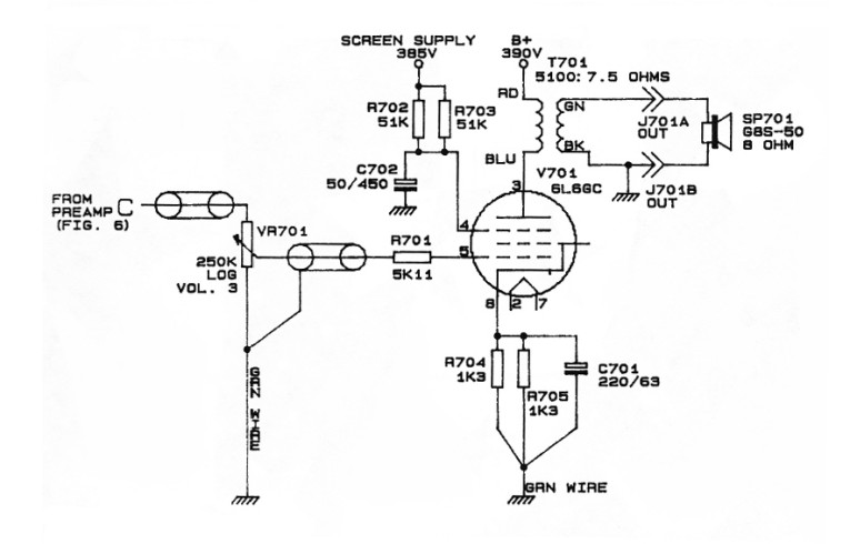
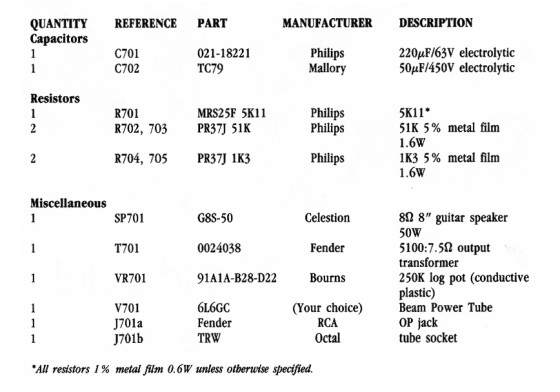
The transformer chosen, a Fender #0024038, outshines the stock Champ transformer in the bottom and in overall power-handling capability. With a nominal impedance ratio of 5100:7.5, it’s ideal for interfacing an 8Ω speaker to a single 6L6GC, an industry-standard guitar tube. Speaker selection is very subjective, so as usual let your ears guide you. I’ve always been a big fan of the throaty sound of Celestions, so I settled on a G8S-50, one of their line of 8 inchers, rated at 8Ω 50W.
The original 6V6GTA output tube had a tendency to fail when driven hard. While the 6L6GC is inherently larger and more ruggedly built, with higher voltage current, and power ratings, I nevertheless felt obliged to identify the specific failure mechanism in this type of amp. It would appear that excessive screen grid dissipation is the culprit. The maximum screen grid dissipation for a 6L6GC is listed at 5W. When the tube is massively overdriven, screen grid current skyrockets, and this rating can and will be exceeded unless preventive steps are taken. I know this because I donned my earplugs and took the measurements.
In Fig.7, R702 and R703 limit screen grid current to a safe value. Like screen grid current, plate current rises alarmingly when the tube overloads. The drop across R702 and R703 lowers the screen grid voltage at maximum warp drive, and this in turn helps keep the plate current at sane levels. For good measure, I put in R701 to limit the control grid current which flows when the positive peaks of the input signal voltage exceed the grid bias potential.
