- on Project Articles
- Article
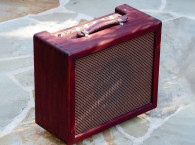
The Remaking of a Champ - Old Becomes New
Stability
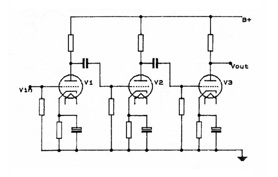
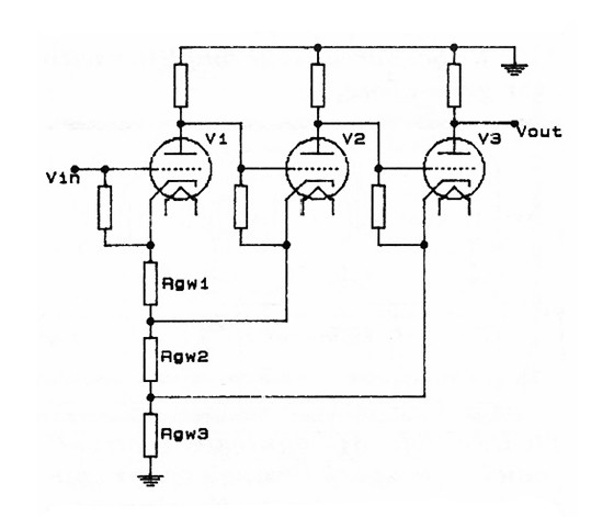
In a high-gain amplifier, power supply and ground impedance can cause feedback and instability. Consider Fig.8a. This three-stage amp looks harmless enough. Imagine the AC equivalent circuit (short out all capacitors and DC voltage sources) and then redraw it as in Fig.8b, where resistances in the ground bus are represented by Rgw1, Rgw2, and Rgw3. Now the true horror of the situation stares us in the face: a multiple feedback amplifier! Since Murphy's Law dictates that unintentional feedback of this nature is generally positive, we can be darn sure this turkey will oscillate.
The solution is simple. Return each stage directly to power supply ground with a separate wire (green ones seem to work best) - the well-known star grounding technique. Figure 8c is the result, and the coupling between stages is eliminated.
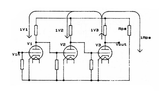
With the ground gremlins gone, let's look at the power supply. An unregulated supply as a non-zero impedance, especially at the lower frequencies. Figure 8d shows the AC equivalent circuit with the power supply impedance represented by Rps. Imagine a signal current iV3 flowing in V3. According to Kirchoff's current law, iV3 will be divided amongst Rps, V2, and V1. Did I say V2 and V1? Wait a minute - that's feedback, isn't it?
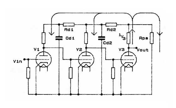
In fact, it's the kind of feedback that tends to induce low frequency oscillations known as motorboarding. The solution is to use RC decoupling between stages, as in Figure 8e. The capacitors provide a low impedance path to ground for the unwanted current feedback. For a good discussion on RC decoupling, check out section 12.36 in Tremaine's Audio Cyclopedia, 2nd edition.
Poor component layout can lead to instability, and this holds for any high gain amplifier, tube or solid state. Keep lead lengths short and direct. Keep higher-level signals away from the lower-level signals to prevent unwanted capacitive and inductive coupling. When signal leads must travel a distance (e.g., to and from the front panel), use shielded cable to minimize capacitive coupling. (Don't worry about losing a bit of the top end driving a capacitive cable from a high impedance tube or pot - you can make this amp as bright as you want with the fixed and variable EQ.) The RCA Receiving Tube Manual has some good advice on layout in the section entitled "Electron Tube Installation."
Construction Hints
The best way to start is to gut the amp. Remove the tubes, sockets, pots, AC cord, fuseholder, main filter can, input 1/4" jacks, power transformer, output transformer, speaker, and all internal wiring and components. Put aside and save for later use the fuseholder, power transformer, and pots. The rest of the stuff is history. Leave the pilot lamp, power switch, and output RCA-jack installed. This is a good time for doing metalwork and for cleaning up and retinning switch, lamp, RCA jack, and pot terminals. I mounted an aluminum box at the rear of the chassis to house the rectifier and filter for the heater supply, and then mounted the 8V transformer to it. The fuseholder ended up on the front panel, and the new AC cord had to find a new spot on the bottom panel.
I used tag strips for most of the internal components. Perfboard seemed to work best for the timing relay circuitry, some of the 6.3V DC regulator components, and C501, C502, R501, and R502 in the main B+ supply. The #0024038 output transformer has no mu-metal end-bells, and can actually pick up a bit of hum from the power transformer. With proper positioning, you should be able to get the hum level at the speaker down to about 1mV p-p. That's extremely quiet - you must have your ear right up to the speaker in a quiet room to hear it at all.
With the new 6L6GC tube, the taller Mallory filter can, and the 8V transformer all hanging down from the chassis, the Celestion G8S-50 wouldn't fit into the original cabinet's front panel. I had to knock it out and install a new front panel with a slightly off-center cutout.
Performance
This amp is capable of great sonic scope. An examination of the block diagram (Fig.2) reveals how, with three preamp stages, three volume controls, and two tone controls, it's possible to control the amount and type of distortion over a wide range. The first preamp stage will generally not clip with typical signal levels from an unamplified guitar pickup. By adjusting the three subsequent volume pots and tone controls, you determine which (if any) following stages will be overdriven, by how much, and at which frequencies. Anything is possible, from super-clean finger-picking to devastating metal power chords that seem to hang on forever.
The amp itself is extremely quiet. It essentially does not hum, even at high gain settings. The limiting factor by a mile in any real life situation is the hum generated in the guitar pickup. In the realm of broadband noise or hiss, there is a similar phenomenon - the thermal noise produced in the resistive component of the guitar pickups' impedance (generally on the order of 20kohms) is more significant than the amplifier noise. This is easy to test, and all you need are your ears and a guitar. Turn the amp up full and listen to the hum and hiss level. Now plug in the guitar. The hum, formerly just about inaudible, will be overwhelming. The hiss will increase dramatically. The guitar is culprit!
To get a rough idea of the power output capability of the amp, I measured the speaker terminal voltage while playing guitar into the amp with all controls up full. My Hewlett-Packard HP400FL read 10V AC on sustained peaks. At these levels, amplifier clipping has so compressed and limited the signal that we can accept this rather sluggish meters' readings as quite valid. There are no peaks sneaking by. Since all we're after is a rough idea, we can use the formula P = V2/R and assume R is 8 ohm, which translates to 12.5W. Now 12.5W may not sound like much power on paper, but let me tell you - this little amp is perfectly capable of shaking walls and alienating the most tolerant of neighbors. Using my Radio Shack 33-2050 sound meter, I measured ambiente levels of 105dB C-weighted in my living room with guitar and Champ cranked to the max.

Fault Becomes Feature
I chose not to apply negative feedback around the output stages, and this is once again an issue largely determined by taste. Negative feedback decreases overall gain, reduces harmonic distortion, flattens the high frequency rise in response due to loudspeaker inductance, and improves the damping factor by lowering output impedance. Without feedback, the amp sounded louder and brighter to me, and I thought that the increased harmonic distortion added character to clean sounds. I also liked the slight woofiness caused by the high output impedance and resultant interaction between speaker and output tube. Many would disagree, including most successful contemporary amplifier manufacturers, who generally apply a moderate amount of negative feedback in their designs. It is worth noting that vintage Champs ran open loop while later designs incorporated some negative feedback. You must try it with and without and see which you prefer.
The subject of tubes versus transistors always generates lively conversations. Guitarists have their own reasons for preferring tube amps, and these reasons stem primarily from the graceful and fascinating nonlinearities displayed by simple tube circuits.
The rather elementary unregulated plate supplies, common in tube guitar amps, cause a form of compression. During peaks, the B+ actually sags, reducing gain and headroom. A vice in a high fidelity amp, but a virtue here: the inherent "boinkiness" of the electric guitar (which you can hear quite clearly in a DI sound, by the way) is controlled and the responsiveness of the instrument is enhanced, since the player can control the amount of compression by how hard he hits the strings and how hot he runs the amp. The somewhat modest output transformers used in these amps are responsible for another compression mechanism - as the output power rises, the frequency response progressively rolls off at the high and low ends. Fault becomes feature: the instrument responds in complex and subtle ways to the player's touch.
Even vs. Odd
A combination of output tube and output transformer nonlinearity produces significant amounts of harmonic distortion you can see on a scope and clearly hear with tones as a signal source. The transformer is very good at adding harmonic texture to low-frequency tones (as you might expect if you've ever messed with audio transformers), while the tube produces the type of asymmetry associated with even harmonics.
Even harmonics produce a more musical and less strident sound than do odd, since they are more closely related to the original signal. Consider for a moment the harmonics of the open A string of a guitar, whose fundamental is 110Hz. The first four even harmonics are 220Hz (note A), 440Hz (also A), 660Hz (note E), and 880Hz (A again). The most distant relative is E, related to A by the constant interval of a perfect fifth. On the other hand, the first four odd harmonics are 330Hz (note E), 500Hz (a Pythagorean c#), 770Hz (a slightly flat G), and 990Hz (a flat B).
Those last two overtones form highly dissonant intervals with the fundamental and the fifth harmonic C#. If you have access to guitar or keyboard, contrast the majestic sonority of a chord composed of octaves and fifths (i.e. even harmonics) with the jarring dissonance of a dominant ninth chord (i.E. odd harmonics). The even harmonics produced by the output stage enrich the harmonic structure of the guitar. One of the benefits of running the output stage open loop is that these distortion products remain undiminished.
Vibrations
The plate resistance of a 6L6GC is around 33kΩ, and when you couple that through a transformer with an impedance ratio of 5100:7.5, the speaker sees a reflected source impedance of nearly 50 ohms. Moderate feedback would reduce that figure, but not to a value that would win any specmanship awards. With this type of amp, you will get some effect from the speaker's back EMF, and that's part of the tube sound. The interaction is rather complex since both transformer and speaker have nonlinear and reactive elements in their impedances.
No matter what anyone says, real world 12AX7As exhibit microphonic behavior. A slight tap on the chassis in the vicinity of a preamp tube can be clearly heard in the loudspeaker. Just imagine a speaker putting out over 11dB of SPL positioned inches away from these same 12AX7As and physically mounted to the same chassis.
This electro-acoustic feedback is a key element in the legendary "tube sound". At high volumes, the acoustic output of the speaker can actually resonate with and sustain physical vibrations of the guitar strings. The sound itself becomes the medium for a dual feedback path involving the vibrations of the loudspeaker, the guitar strings, and the tube electrodes. Try to duplicate that one with transistors!
Ohm's Law
Now, what happens when tubes actually clip? First of all, as signal levels approach clipping, there is a gradual overload, a progressive rounding and flattening of the waveform. The instrument offers a whole range of distortion, from subtle to extreme. When actual clipping finally does occur, it does so when the positive peaks at the grid exceed the cathode bias potential. When the grid is driven more positive than the cathode, grid current flows, and the waveform clips asymmetrically, producing primarily even harmonics.
Soft clipping and asymmetrical clipping occur in both preamp and power amp stages. There are some rather interesting phenomena associated exclusively with power amp stage overload, phenomena both rich and dynamic. The quiescent or DC bias conditions determine in great measure the operation of the output tube. Some of the quiescent or DC parameters include plate-to-cathode voltage, grid-to-cathode voltage (usually negative), screen grid-to-cathode voltage, cathode-to-ground voltage, plate current, and screen-grid current.
Apart from the obvious Ohm's Law relationships between these various parameters, there are other relationships which can be gleaned from a good set of plate and transfer characteristic curves. When the tube is overdriven, the relationships become nonlinear and dynamic. In effect, the signal voltages cause changes in the DC operating conditions, which in turn cause changes in the way signal voltages are processed by the tube.
To look at an elementary example, large signal voltages tend to increase plate current. Increased plate current causes an increase in grid bias (due to the increased flow through the cathode resistor) and a drop in B+, both of which tend to oppose the rise in plate current. The screen grid current also rises when the output tube is hit hard. The resulting voltage drop across the screen grid resistor reduces the screen grid voltage, as do the increased drop across the cathode bias resistor and the drop in B+. Lower screen grid voltage reduces plate current.
If you plug in a guitar, turn up to 11, hit a chord, and monitor the output tube's cathode voltage on a scope, the movement you see reflects changes in overall DC tube current resulting from the interplay of many factors. As the notes in the chord develop and decay, the operating or DC conditions of the output tube change, and generate a rich and flowing array of sonic textures.
Old Becomes New
Deterministic nonlinear systems, especially systems with feedback, yield complex aperiodic behavior. In his book Chaos, James Gleick discusses systems of this nature and how apparently chaotic behavior often hides a deeper order. Elements of chaos abound in nature and are instrumental in producing life's rich pattern.
So let's forget about building a solid-state amp that sounds like tubes. Power supply and transformer compression, output stage harmonic distortions, high output impedance, feedback via preamp tube microphonics, generation of even harmonics, soft clipping, asymmetrical clipping, and signal-induced bias modulation - all these factors are inherent in simple tube circuits. Complex solid-state circuits might be able to ape some of this behavior, but certainly not all of it, and in any case not precisely, so what would be the point?
In modern studios, it would appear that each technology is allowed to do what it does best. Tube guitar amps, mikes, preamps, equalizers, an limiters coexist and cooperate with solid-state signal acquisition, storage, and manipulation devices, both analog and digital. There is an old and there is a new, and each has its place and purpose.
With a bit of effort, an old practice amp can be converted to a studio-quality unit. If you've got an old guitar amp lying around the house, why not dust it off and polish it into a little gem? It will be a rewarding and enjoyable way to learn about tubes.
This article was originally published in Glass Audio Volume 4, Number 2, 1992 (In 2001, Glass Audio magazine, published by Audio Amateur Publications was merged with Speaker Builder and Audio Electronics magazines, creating audioXpress).
 Author's Acknowledgements
Debra Elliott, Dean Cavill, Andy Ryan at The Playroom Recording Studio; Earl Torno at Phase One Recording Studios; Danny Devion of Avenue Road; John Fouch, Susan Hooper at Fender Musical Instruments; Gerry Tegmeyer at Woodward-Schumacher; and Eileen at Richardson Electronics.
References
1. Gleick, James - Chaos, Penguin Books, 1987.
2. Langford-Smith, F. - Radiotron Designers Handbook, 4th ed. Amalgamated Wireless Valve Co. Pty. Ltd. Sydney, Australia, 1953.
3. Manley, David - The Vacuum Tube Logic Book, VTI, 1988.
4. Malvino, Albert P. - Electronic Principles, McGraw-Hill, 1973. pp 272-277
5. Pittman, R. Aspen - The Tube Amp Book II, Groove Tubes, 1988.
6. Tremaine, Howard M. - Audio Cyclopedia, 2nd ed., Howards Smas & Co. Inc., 1969.
7. RCA Receiving Tube Manual, RCA Corp., 1974.
8. Voltage Regulator Handbook, National Semiconductor Corporation, 1982.
About the Author
Kirk Elliott is a graduate of Ryerson Polytechnical Institute in Toronto, and has worked since 1979 in professional multitrack recording facilities. He gained an appreciation for tube technology by working on Pultec EQs, old Neumann mikes, EMT plates, tube limiters, and Fender and Marshall guitar amps. His designs see frontline use in major studios in Toronto, Los Angeles and New York.
More on The Champ!
Read another Fender Champ project published by audioXpress in January 2016. The article "Revisiting The Remaking of a Champ", by Mark Driedger, was inspired by Kirk Elliott's article but introduces a few interesting variations, including a provision to easily try different output tubes.