But first, we should make the distinction between single panel and segmented panel ESLs. Single panel ESLs as built by MartinLogan and others are basically a diaphragm between two stator plates, a physically large capacitor, with a large capacitance between the stators. Designing a direct drive amp for such a speaker may require up to 100mA rms current or more at full power and high signal frequency.
At the other end of the spectrum are the segmented ESLs, where parts of the diaphragm are segmented in separate areas or strips, either mechanically by clamping or electrically with the segments connected via R-C networks or transmission lines. Which segments are active and emitting sound at any one time depends on the signal frequency. Segmentation is done to control high-frequency beaming of the speaker, but such speakers also present a more benign load to the step-ups, and a high-voltage direct drive would require maybe up to 20mA rms, and that is much easier to design and build. My direct drive amplifier has been designed with the QUAD ESL63 and its derivatives in mind, with a design goal of 1500V rms at 20mA rms over the full audio band.
The obvious question is why there are so few commercial amplifiers to drive electrostatic loudspeakers directly, to circumvent the complexity and cost of the step-up transformers, filtering components and stringent power amplifier requirement. There have been a few developments in the past but these direct-drive amplifiers were complex to be able to manage the very high voltages, therefore expensive, and often unreliable. Due to limited experience with high voltage amplifiers at service centers, it was hard to get a defective direct-drive amplifier repaired reliably and affordably. Most direct-drive amplifiers offered on the Internet are defective in one or both channels.
Design Considerations
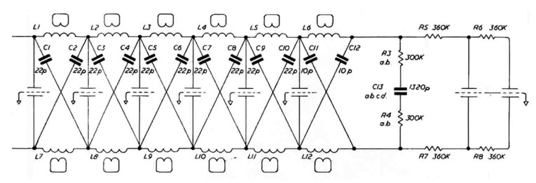
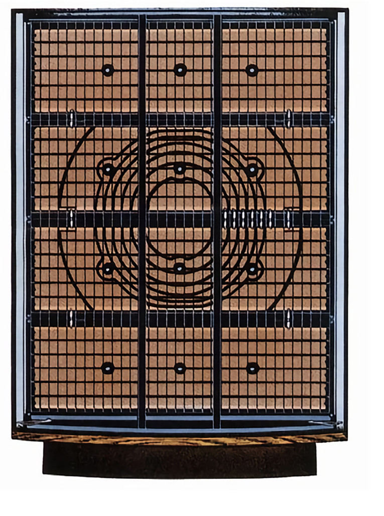
The QUAD ESL63 is an electrically segmented ESL, meaning that the different audio frequency ranges are routed to different (circular) segments of the diaphragm. Figure 1 shows the circuitry of an ESL63, from the output of the step-up transformer at the left side, to the stator elements. The dotted lines in the middle with the bent arrows are the diaphragm segments. This is a transmission-line like structure, and the segments are circular in shape. Figure 2 shows the construction.
I decided to use a bipolar supply for the amplifier. My target was 1.5kV rms out, necessitating a 4.4kV total supply voltage. That is scary to have in an amplifier box, so I decided to go for ±2.2kV. It does complicate the supply but should help with reliability (and still is scary!).
From the beginning I have been weary of stability issues for an amplifier with a dominantly capacitive load. (I only later decided to target the QUADs, which have more benign load characteristics.) It seemed that the best approach would be to design a current output amplifier that would give the amplifier-capacitive load combination a first order low pass response. That means I could wrap feedback around the amp to lower distortion and set the output impedance to whatever I wanted without having to worry about stability. This also appeared to combine well with the fact that an ESL SPL is linearly related, first order, to the stator current, not voltage, as derived by Peter Walker in his famous “Walker equation” [2]
I built some prototypes using high voltage MOSFETs and IGBTs output devices. These worked fine — if the frequency remained below a few kilohertz. These high voltage devices can withstand up to 4.5kV and conduct several amps but are basically designed for switching applications. They have very large and nonlinear inter-electrode capacitances that vary with voltage levels. In switching applications that is no issue, you just drive them as hard as needed. But their internal (nonlinear) capacitances are so large that they totally dominated my amplifier load, being several times as large as the speaker they were intended to drive.
An additional complication was that those switching high-voltage devices are not suited for linear operation due to the Spirito effect, which has a similar destructive effect as secondary breakdown in a bipolar power device [3]. After discussing the problem with some of my audio friends, one asked if I had considered using tubes as output devices. This was a good friend so I forgave him for his impertinence, but he got me thinking. I got myself a couple of 6HS5s, unsoldered the IGBTs in the prototype output stage, connected the tubes with some external heater supplies, switched on the prototype and all my issues were gone! My circuit design was sound, I had just used the wrong output devices. It was all downhill from then on.
The Output Stage
The basic output stage design is shown in Figure 4. The bottom tube U4 is loaded by a constant current source (U1), for a high impedance current output characteristic. Ideally, I would have selected a pentode to get the high output impedance, but that would require an additional floating screen supply. Tube availability in this class of voltage, current and power levels is limited, and I decided on the 6HS5, which is a beam triode.
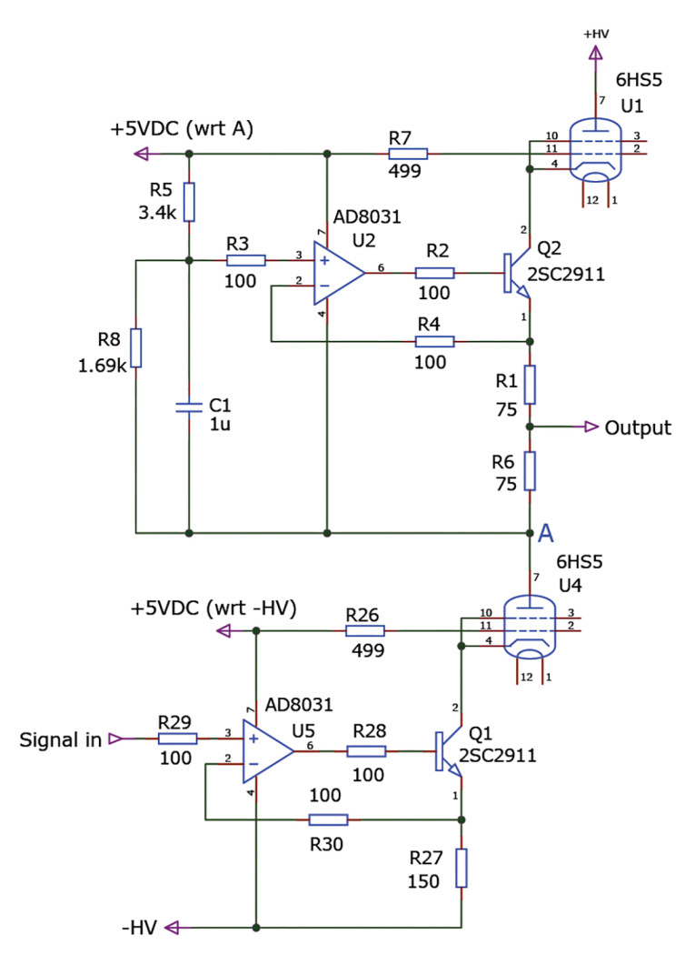
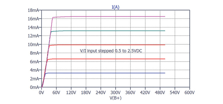
To give it pentode-like characteristics, I used the tube in common grid, driving it at the cathode from a voltage to current converter. (Viewed from the voltage to current converter you could call it a cascode, but what’s in a name?) Figure 5 shows the output curves for U4 triode-turned-pentode in the Figure 4 circuit, recorded with “Signal in” stepped from 0.5V DC to 2.5V DC in 0.5V DC increments. The curves are nicely flat indicating a very high output impedance.
Next up is the constant current source (CCS) load, U1, another 6HS5. I used the same trick, driving it in common grid so it functions as an almost ideal CCS. This completes the output stage. It runs at around 10mA bias, so the Class-A output current range would be ±10mA peak, slightly less in practice.
Now we apply a little trick that was pioneered by Nelson Pass and goes by various names (i.e., modulated current source or active current source). We do not pick off the signal from the anode of the driver or from the cathode of the CCS, but from a point halfway (R1–R6 in Figure 4). The effect is that when the driven tube U4 pulls more current from the load, there is more voltage across R6. Since the voltage across R1+R6 is constant (R5–R8 divider from the 5V DC bias), the voltage across R1 must decrease which means that the CCS current decreases. This helps U4 to pull down the output. Conversely, if U4’s current decreases, the voltage across R6 decreases, the voltage across R1 increases, which means that U1 drives more current into the load. In theory, the result is a symmetrical output current twice the peak value of the simple CCS loading. In practice, the output current is some ±18mA peak, ample for the QUADs.
The Tube Heater and the Bias Supply
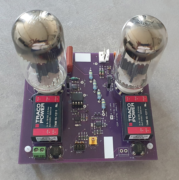
Note that for U4, the 5V DC power supply for the grid bias, the heater supply, and the cathode drive op-amp are referred to the -2.2kV supply. For the CCS, the heater, bias, and op-amp supply, which are referred to point A in Figure 4 are swinging with the output signal. So, these auxiliary supplies should have good isolation from the high voltages involved. The swinging supplies for the U1 CCS should also have low capacitances to the rest of the universe to avoid losing load current into those parasitics. The solution is a pair of medical-grade isolated DC-DC converters. The Traco THM 15-1211 accepts a nominal 12V DC input and transforms that to a 5V at 3A output. They can withstand up to 5kV, and, better yet, have just 20pF between input and output (Photo 2).
That 5V DC output is too low for the 6HS5 heater (nominal 6.3V), but the Traco can be trimmed up to 5.7V, and I accepted that the 6HS5 would run at the bottom of its heater voltage range. The tubes do not run anywhere to their specified maximum current, so I felt comfortable with that. For the 5V DC supplies for the grid bias and op-amp supply I used a low dropout low noise linear regulator (ADP7118-5.0) to get that 5.7V DC heater back to 5V DC with very low ripple and noise. Figure 6 shows that part of the system.
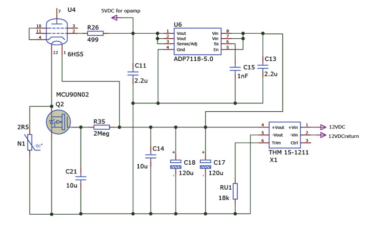
A 12V DC AC-DC converter in the system provides 12V DC to X1, the medical grade DC-DC converter THM 15-1211. The output is trimmed up to 5.7V DC by RU1 and is used as input to the ADP7118-5.0, which provides a regulated low noise 5V DC for the grid bias as well as to the op-amp that drives the voltage to current converter at the cathode. The heater voltage for the tube has a soft start system required to prevent overloading X1 when the heater is cold. Initially, an NTC N1 limits the heater inrush current. After a short while, C21 gets charged to 5.7V DC through R35 and MOSFET Q2 is fully on, with just 8mΩ resistance shorting out N1 so the full 5.7V DC is applied to the heater.
The Transconductance Drive Circuit
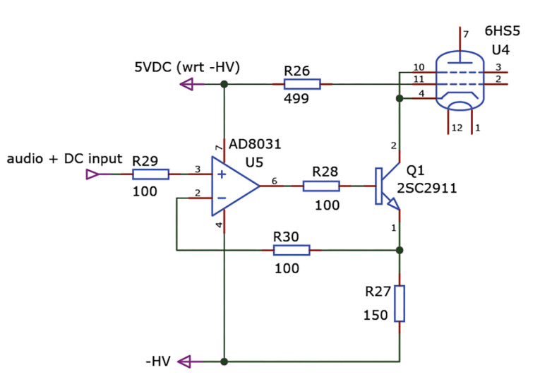
This is a straightforward application of an op-amp configured as a voltage-controlled current source, as depicted in Figure 7. U5 is a wideband op-amp with rail-to-rail input and output range and able to work on just 5V supply. Its output will drive the base of Q1 until the voltage across R27, fed back to its inverting input, matches the input voltage at its non-inverting input. That makes the current through R27 — which is also the cathode current of U4 — the input voltage/150Ω. The DC component of the input is about 1.6V setting the DC bias of U4 to approximately 10.7mA.
Output Stage Audio Input
You probably noted that the input to the voltage to current converter driving U4’s cathode is also referred to the -2.2kV supply. So, I need to bring the audio signal down from the ground referenced input to the negative supply reference. Figure 8 shows the circuit. U1 is an analog optocoupler with some unique characteristics. There is a single LED that is optically coupled to two matched photodiodes. Therefore, the two diodes will both conduct the same current from the LED output flux. The two diodes are matched to 0.1%, which is, in distortion terms, better than -60dB.
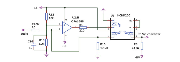
Assume that the voltage at pin 5 of U2:B is zero. U2:B then drives the LED in U1 such that the current through R16 is the same as the audio current through R6 but in opposite phase, which would put the inverting input of the op-amp at zero volts as well.
Because of the photo diode matching in U1, the currents through R16 and R3 are identical, so the voltage across R3 will be a faithful representation of the audio input voltage but isolated from the input circuit and ground and referred to the negative high voltage. We assumed that the input at the non-inverting input of U2:B was zero volt, but in reality, it has about 1.6V DC bias from the R12-R13 voltage divider. The upshot is that across R3 you find not only the audio input signal but also 1.6V DC bias which, as described, sets the bias of U4 to nominally 10.7mA.
Overall Circuit Diagram
Figure 9 shows the amplifier input stage. The forward path contains a gain of six stage, U3:A. The output of this stage drives summing stage U2:A through R2. Summing stage U2:A sums the amplified signal with the feedback signal coming from the output through the high impedance string with the 1MΩ resistors R5-R19-R20-R21. The gain of the output stage is thus 200, set by the ratio of this string to R2. D3 and D4 are there to protect U2:A and U3:A. The output of the summer drives the isolation amplifier U2:B, described earlier, which drives the voltage to current converter driving U4. Since the feedback is DC coupled, this automatically nulls the DC offset at the output. The amplifier output impedance is around 4kΩ over the audio band.
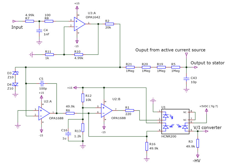
DC output offset in this type of amplifier is a different issue than in regular power amplifiers, as there is no low-impedance load to draw offset current. Rather, an output DC offset pulls the diaphragm off center, and in that manner does decrease the symmetrical output signal available. But to put it in perspective: my amplifier has about 1V DC output offset for a symmetrical output level of ±2.1kV. I do not think it will audibly limit the output.
Power Supply System
The amplifier requires several power supplies. I already mentioned the floating tube heater and bias supplies, provided by the isolated DC-DC converters. The isolators are supplied by an AC to DC converter with 12V output at several amps. The control system with the controller (described later) requires a 5V supply. The various op-amps in the preamp and driver stages require ±15V DC. The 12DC, +5V DC and ±15V AC-DC converters are universal mains input (90V to 240V) converters. Where I live, mains voltage is nominally 230V AC. That means that the amp will work fine at half mains input, which allows operation at reduced high voltage through a variac. This was great for my peace of mind during development.
The 5V standby for the controller is always on, but the 12V DC to feed the heater converters is switched on through a solid-state relay, and the DC-DC converter for the ±15V low level circuits supply has a switching input which can be directly controlled from 5V logic. Both are switched on by the controller (described later).
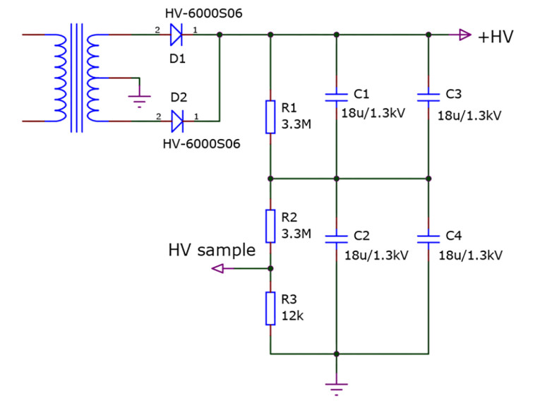
The final stage high voltage DC is provided through a custom high voltage toroid. Menno Vanderveen helped to specify that transformer and I had it manufactured by his TRAFCO partner in Belgrade, Serbia. Output at nominal mains is 3.2kV center tapped for 50mA continuous DC load and it performed exactly as specified. It is a large transformer due to extensive use of isolation material. Figure 10 shows the positive 2.2kV supply, and the negative supply is similar (with opposite polarity diodes), with resistive capacitor balancing and a tap of the output DC allowing the controller (described later) to sense and display the high voltage DC for measurement purposes. The caps are polyester foil. The high voltage is switched on by the controller through a solid-state relay in its primary feed.
System Sequencing, Control, and Setup
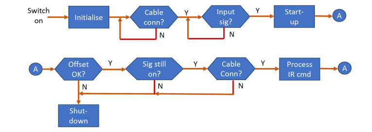
From the beginning of my experiments, I have been cautious when working on the amp. One hand in the pocket, no wristwatch, rubber-soled shoes, the works. I would switch on the next supply only after the previous state was verified as working correctly. At an early stage I decided to include a microcontroller in the system for sequential power-up and health checking. Having previous experience with Microchip controllers I selected a PIC16F15356. I have been using Flowcode [4] (now on version 10) as my programming environment as it is graphically oriented and avoids having to worry about low level routines and libraries. Figure 11 shows the main logical flow.
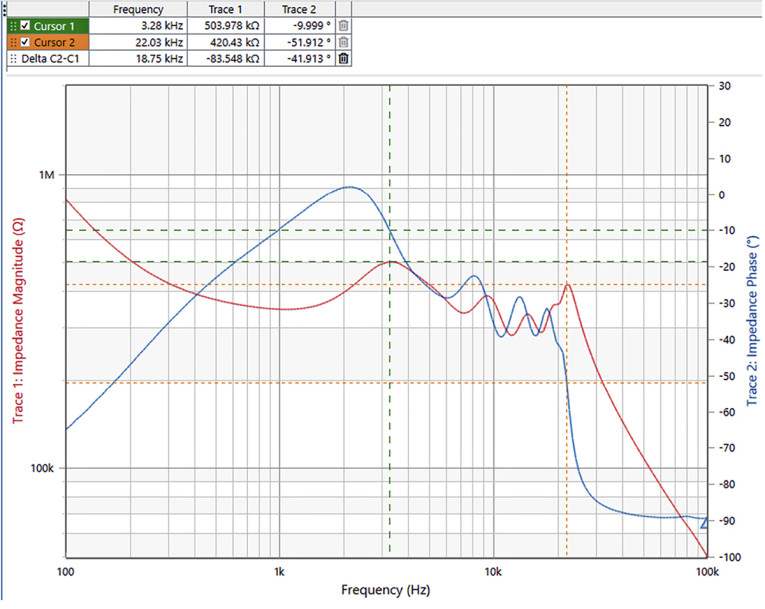
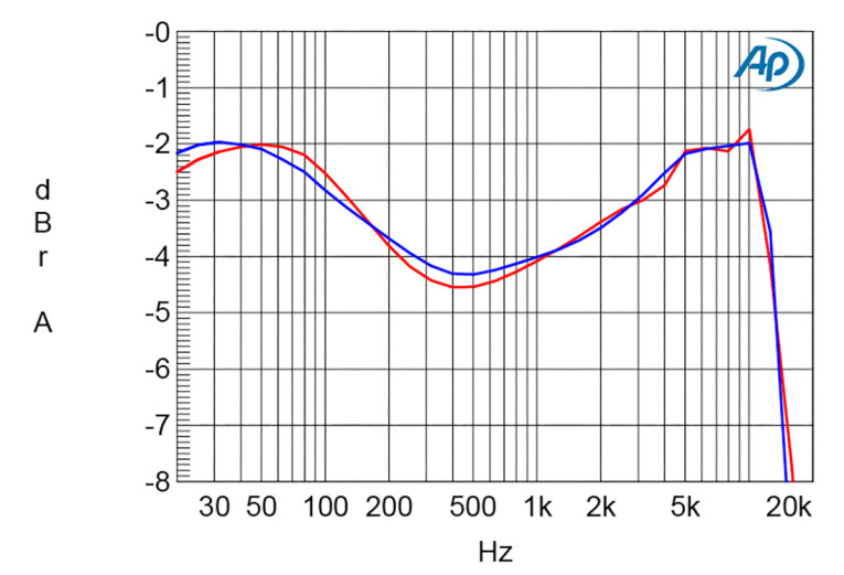
There is also an IR receiver in the amp, through which I can make the controller send a command to the speaker through an extra wire in the amplifier-speaker umbilical. There are four high-voltage relays inside the speaker that switch the stators between the direct-drive input signal and the output of the step-up transformers. With that facility, an instant remote-controlled listening comparison is possible. The direct-drive amplifier and the step-up amplifier are each driven from a stereo DAC in an RME ADI-2 Pro FS R. The signal to the direct-drive amp is equalized to match the frequency response of the step-up at the stators and both are level matched. Figure 12 shows the frequency responses. I spent quite some effort on a special precision, high-voltage, flat response 1000:1 attenuator so I could measure directly on the stators with the Audio Precision, without burning it out with the high voltage.
The Bottom Line
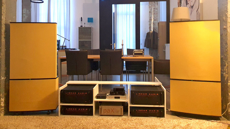
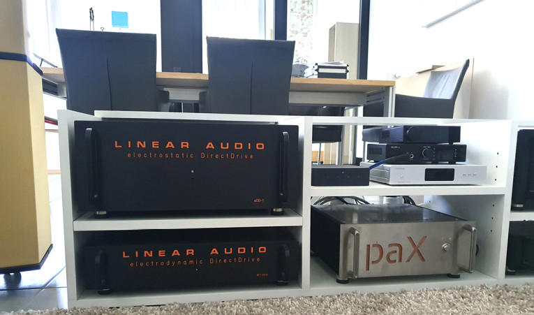
This project, while not a simple or quick one, proves that it is perfectly possible to design a well-performing and reliable high voltage amplifier to directly drive electrostatic speakers of the QUAD ESL 63 family (Photo 3). The amp does not reach the drive levels of a traditional drive through a step-up transformer, but it produces very loud SPL levels in a living room setting. It just took me a long time as I had to design and work through unfamiliar and potentially lethal circuitry. Except for the high-voltage transformer, no special or custom parts were needed, everything is basically available from the usual distributors albeit sometimes with a backorder.
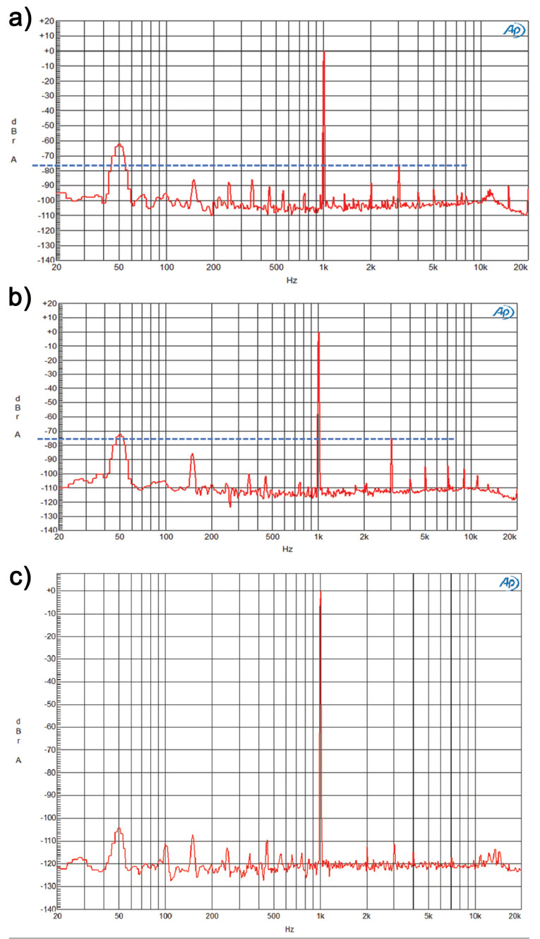
Listeners at several informal listening sessions unanimously stated that direct drive provides a more natural and detailed, high-resolution reproduction compared to traditional step-up drive. This difference is supported by Figure 13, which shows that, measured at the stators, the direct drive amp has substantially lower distortion compared to step-up drive. The Purifi and paX amplifiers both have less distortion than what is shown in the graph, and I contribute the difference to the step-up transformer.
Using high-voltage solid state output devices was not successful, although, at the time of this writing, 2.5kV MOSFETs for linear operation are becoming available. But the large interelectrode capacitances remain a challenge. Readers seriously considering a similar project can contact me for further information and details. aX
References
[1] P. Walker, et al., UK Patent 815.978, 1955
[2] P. J. Baxandall, ”Electrostatic Loudspeakers,“ Chapter 3 in Loudspeaker and Headphone Handbook, John Borwick, Editor, Taylor & Francis, 2001
[3] The Spirito Effect, www.youtube.com/watch?v=oogXjjYKDyk
[4] Matrix Flowcode, www.matrixtsl.com/flowcode
Resources
D. Hermeyer, “An Electrostatic Speaker,”
The Audio Amateur, Issue 3/1972, p. 11.
D. Hermeyer, “Electrostatic direct drive amplifier,”
The Audio Amateur, Issue 4/1972, p. 9.
Steen Frank Jansen website,
http://steenfrankjensen.com/projects/electrostatic-loudspeaker
Jazzman’s DIY Electrostatic Loudspeaker Page, by Charlie Mimbs (Jazzman) on segmented ESLs, http://jazzman-esl-page.blogspot.com
R. Sanders, “Electrostatic speaker,” The Audio Amateur, Issue 4/1975, p. 18.
R. Sanders, “Electrostatic direct drive amplifier,”
The Audio Amateur, Issue 1/76, p. 12.
F. Verwaal, “The Design of Electrostatic Loudspeakers,” 2017, Rev. 2, www.scribd.com/document/63688628/The-Design-of-Electrostatic-Loudspeakers-Frank-Verwaal-2011.
This article was originally published in audioXpress, December 2023.