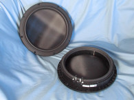
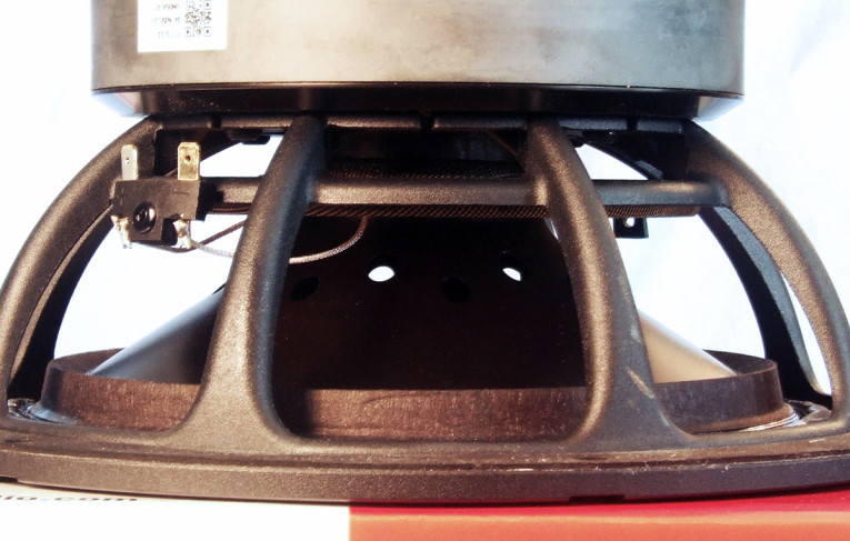
The feature set for the PTT8.0X04 begins with a proprietary eight-spoke cast-aluminum frame, comprised of narrow (about 13mm to 7mm) tapered spokes, completely open below the spider (damper) mounting shelf for cooling (Photo 2). Additional cooling for this driver is provided by 16 oval-shaped 8mm×5mm vents surrounding the cone neck joint beneath the dust cap, with no pole vent. This is a good configuration as it drives more air over the front plate for improved cooling.
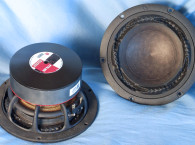
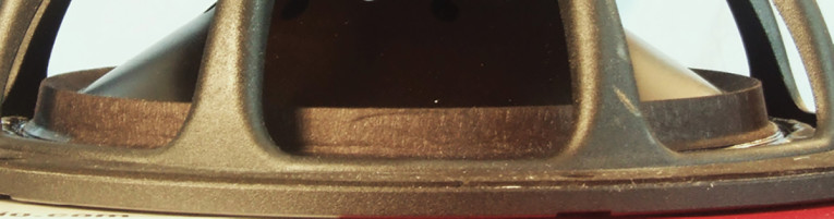
The cone assembly consists of a slightly curvilinear profile black anodized aluminum cone, a 3.5” convex black anodized aluminum dust, plus the addition of a V-shaped edge fiber reinforcing ring glued around the outside rim of the back side of the cone (Photo 3). This reinforcing ring makes the cone edge extremely stiff and would obviously severely dampen cone edge resonances.
Compliance is provided by the NBR surround, which like the PTT6.5X and the PTT4.0X surround is an entire story. This is obviously like no other surround in the history of woofer development. Surrounds, besides providing compliance and centering, are indeed a source of noise and distortion as well as a tool for damping the outside rim of a cone. It is not a surprise that surrounds have been the subject of numerous patents that offer solutions based on shape, material, and complex material thickness, but I have yet to see anything this articulated.
The PTT8.0X, as with all the Purifi drivers, has a surround configuration that is a combination of alternating sections of both reverse roll and positive roll, plus some interesting undulations within the alternating sections. The positive roll has an obvious left/right asymmetry, which yields a positive/negative going articulation on either end of the reverser roll sections. Remaining compliance is provided by a 34.5” diameter symmetrical roll flat spider. (The individual rolls themselves are asymmetrically shaped, with steeper slope on one side and a shallower slope on the other.)
The motor consists of an FEA-optimized 138mm×25mm ferrite ring magnet with milled and tapered plates, with both plates having a black emissive coating, plus a pole piece comprised of a neodymium pole magnet sandwiched between steel sections that serves to linearize the Bl.
Driving the cone assembly is a 52mm (2”) diameter substantial four-layer voice coil wound with round aluminum wire on a non-conducting fiberglass former. Like the surround, this four-layer coil also exhibits some unique engineering. Unlike a winding that has the same width across its full length, this four-layer coil has alternating two- and four-layer sections on the length of the coil with varying widths of two- and four-layer sections,
Most of the pole is replaced by a strong neodymium magnet: This reduces the coil inductance significantly as well as the inductance vs. position gradient all the way to DC (according to Purifi, this cannot be achieved by shorting rings since they only work above a certain frequency determined by the rings cross-sectional area). An iron pole piece extension (hat) is optimized to flatten the inductance vs. position further. This virtually eliminates the current dependency of the Bl factor as well as the position dependency of the coil impedance—two major nonlinear sources of especially IMD (changing the Bl or coil impedance modulates the sensitivity of the speaker leading to amplitude modulation). Two very thick copper shorting rings are surrounding the coil within its full linear stroke.
The purpose of these is to further lower the inductance and shield the iron from the AC field of the coil. Having an AC field in the iron is a major source of distortion (hysteresis and BH saturation). Note that the top ring extends through the gap since the AC field induced in the iron concentrates at surfaces close to the coil and thus needs the most shielding. The pole ventilation is through holes in the cone assembly to get enough venting area to eliminate air rushing noises.
Other features include 350W IEC268 long-term power handling rating, a 9.3mm Xmax, and voice coil tinsel braid lead wires that are terminated to gold-plated solderable terminals located on one side of the frame.
I began testing the Purifi PTT8.0X 8” woofer using the LinearX LMS analyzer and the Physical LAB IMP Box (same type fixture as a LinearX VI Box) to create both voltage and admittance (current) curves with the driver clamped to a rigid test fixture in free-air at 0.3V, 1V, 3V, 6V, 10V, 15V, and 20V with the oscillator on-time between sweeps to simulate the actual thermal process over time. The 20V curves were not sufficiently linear to get an adequate curve fit and were discarded.
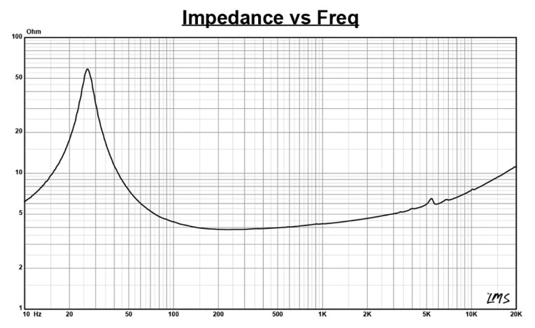
Following my established protocol for Test Bench testing, I no longer use a single added mass measurement and instead use the company’s supplied Mmd data (41.13 grams for the PTT8.0X). The collected data, in this case the 12 550-point (0.3V-15V) sine wave sweeps for each Purifi sample were post-processed and the voltage curves divided by the current curves to generate impedance curves, with the phase derived using the LMS calculation method, and along with the accompanying voltage curves, imported to the LEAP 5 Enclosure Shop software. Figure 1 for the 1V free-air impedance curve. Table 1 compares the LEAP 5 LTD/TSL TSP data and factory parameters for both Purifi PTT8.0X04-NAB-02 samples.

LEAP LTD and TSL parameter calculation results for the Purifi woofer correlated reasonably well with the published factory data, with a 2dB difference in 2.83V sensitivity. My number is a TSP calculation result, and Purifi uses a 300Hz to 800Hz measurement referenced to 20µPa. As usual in this column, I followed my established protocol and proceeded setting up computer enclosure simulations using the LEAP LTD parameters for Sample 1. Two simulated enclosures were programmed into the LEAP 5 software, a Butterworth (Qtc=0.7) sealed enclosure with a 0.71ft3 volume and 50% damping material (fiberglass) and a QB3 vented box in a 1.08 ft3 volume with 15% damping material (also fiberglass) tuned to 28Hz.
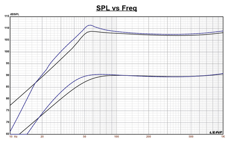
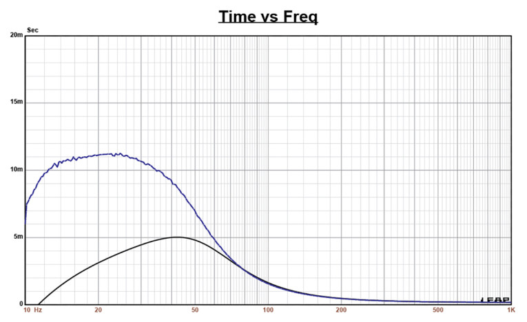
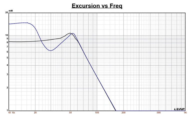
Figure 2 displays the box simulation results for the PTT8.0X woofer in the sealed and vented enclosures at 2.83V and at a voltage level that achieves excursion equal to Xmax+15% (10.7mm for the PTT8.0X). This resulted in an F3 of 49Hz (-6dB=39Hz) with a Qtc=0.69 for the closed box and a -3dB for the QB3 simulation of 39Hz (-6dB=32Hz). Increasing the voltage input to the simulations until the Xmax+15% excursion was reached resulted in 109dB at 26V for the sealed enclosure simulation and 111dB with the same 29V input level ported box. Figure 3 shows the 2.83V group delay curves. Figure 4 shows the 26V/29V excursion curves. Using a third- or fourth-order active high-pass filter at 20Hz would result in lower excursion and higher output capability for the vented incarnation.
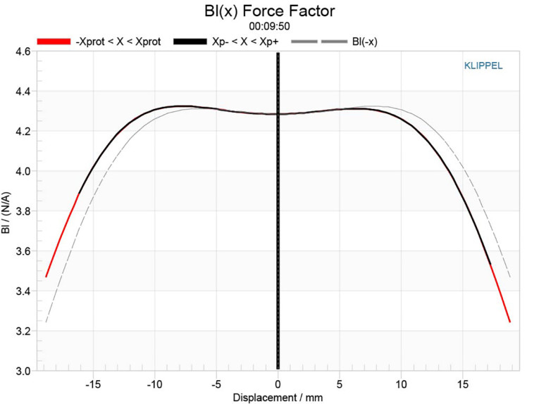
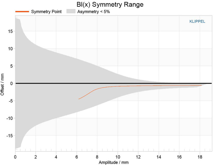
Klippel analysis for the Purifi 8” woofer was performed by Patrick Turnmire of Redrock Acoustics with the Klippel DA2 analyzer. The results are displayed in Figures 5-8. The Bl(X) curve for PTT8.0X (Figure 5) is very symmetrical, with a wide Bl profile of a high Xmax woofer and only a minor amount of asymmetry. The Bl symmetry range curve (Figure 6) shows about ≤0.9mm rearward offset at a point of certainty outward.
The Kms Stiffness of Compliance curve (Figure 7) is broad and with a degree of asymmetrical behavior and a small amount of “tilt”. Looking at the Kms Symmetry Range curve (Figure 8), the device exhibits a small degree of rearward (coil-in) offset at 3.5mm excursion (0.88mm rearward offset) to about 6mm (zero offset), where it transitions to a small amount of forward (coil-out) offset at the physical 9.3mm Xmax coil position (1.2mm forward offset).
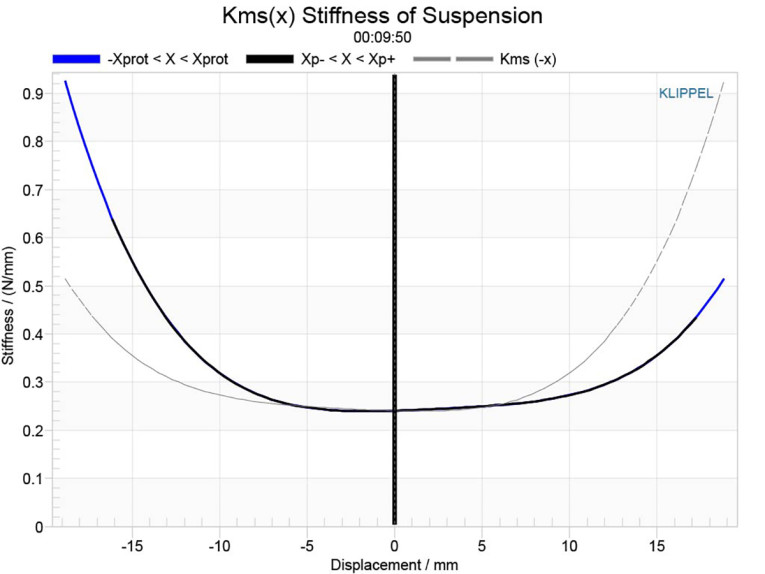
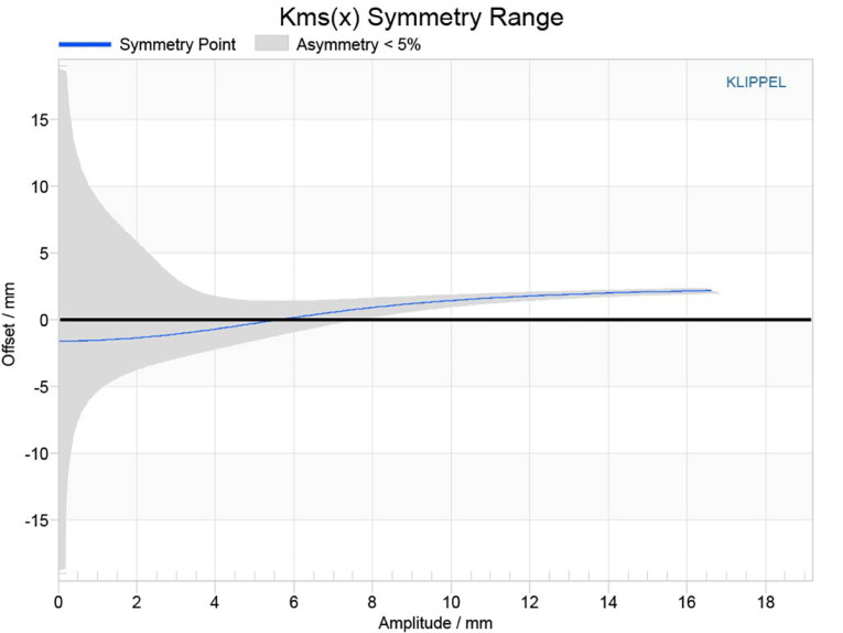
Figure 9 gives the inductance curve Le(X) for this transducer. Motor inductance will typically increase in the rear direction from the zero rest position as the voice coil covers more of pole in a conventional motor, which is not exactly what you see in this graph, but this is also not a conventional motor. More important, the inductive “swing” from Xmax in to Xmax out is an amazingly small 0.002mH, which I think is the lowest inductive swing than any previous Klippel analysis has revealed. Purifi has come up with an unquestionably complex motor structure, but the distortion and inductive performance is absolutely outstanding.

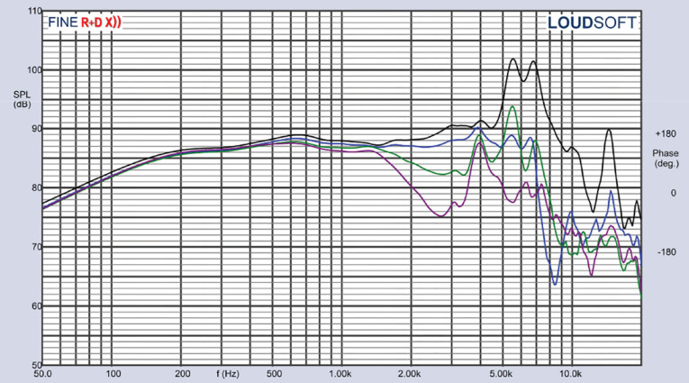
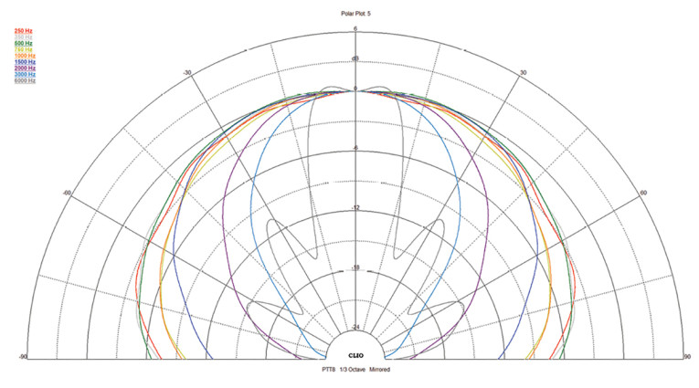
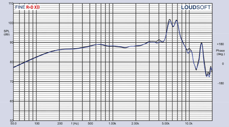
Figure 10 gives the Purifi PTT8.0X04-NAB-02 on-axis response indicating a rather smooth response that is ±1.5dB from 300Hz to 3kHz, followed by break-up mode peaks between 4.5kHz to 8kHz where the driver begins its low-pass roll-off with a final break up mode peaking at 15kHz. Figure 11 displays the on- and off-axis frequency response at 0°, 15°, 30°, and 45°, with -3dB at 30° with respect to the on-axis curve occurs at 1.8kHz, so a cross point in that vicinity or lower should work well to achieve a good power response and directivity index curve.


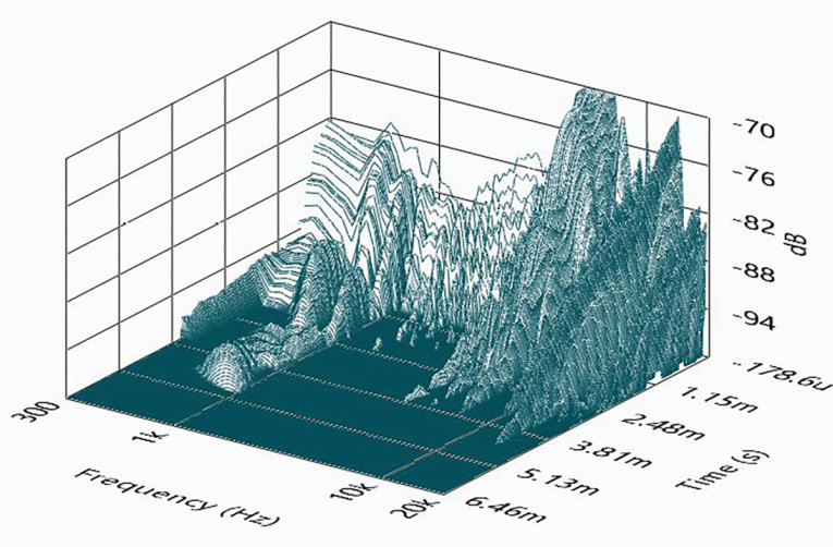
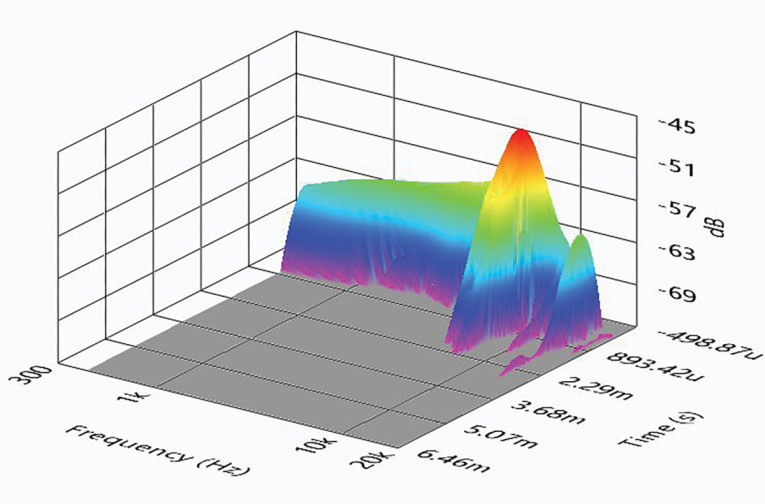
I engaged the SoundCheck software to get a 2.83V/1m impulse response for this driver and imported the data into Listen’s SoundMap Time/Frequency software. Figure 16 shows the resulting cumulative spectral decay (CSD) “waterfall” plot. Figure 17 shows the Wigner-Ville surface plot (chosen for its better low-frequency performance).
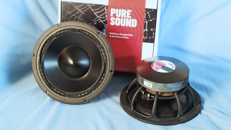
For a relatively new company, Purifi Audio has unleashed an impressive ever-growing line of transducer designs and combined this with a high level of build quality. The PTT8.0X04-NAB-02 is a well-crafted 8” transducer that would do well designed into the two- or three-way high-end two-channel hi-fi, home theater, or studio monitor markets.
As with all the Test Bench reports I publish in Voice Coil magazine, I regret not being able to design these drivers into a system and do a proper subjective evaluation For more information about this woofer and other Purifi Audio products, visit
www.purifi-audio.com. VC
This article was originally published in Voice Coil, December 2023