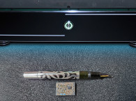
When it comes to wiring techniques, first up is the BCD rotary switch, where BCD stands for Binary Coded Decimal. Photo 1 shows the rear of an audio test device that I built in 2018, and mentioned in the June 2019 issue of audioXpress magazine. The rotary switch to the left of the white VU meter in the middle of the panel has 11 positions to adjust amplifier gain from 0 through 100dB. So a total of 12 wires are needed, including the common connection. If I had used a BCD switch, only five wires would be needed.

BCD Switches
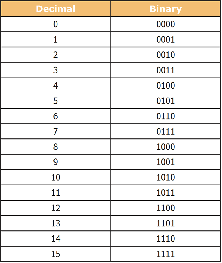
Photo 2 shows the construction of a conventional three-position rotary switch. In this rear view, the terminal at left is called the Common, and it connects via the metal slider one at a time to the other three terminals. Here, the switch is in the middle #2 position. In contrast, a BCD switch outputs a binary number that identifies the current switch position. Using binary numbers accommodates up to 16 positions, using only four output terminals plus the common. Table 1 shows the 16 values 0-15 that can be represented by four binary digits.
So instead of a common contact that connects alternately to terminals 1, 2, 3, and so forth, the common contact in a BCD switch is typically connected to the power supply. The supply voltage appears in 16 unique combinations at the switch’s four output terminals, and an inexpensive logic IC then decodes the output number and sends it on to the host device to process. So using a BCD switch when appropriate can reduce the high cost of human labor to solder the switch terminals and additional wire connectors. It can also save on the cost of expensive copper when the wire runs are long. One example of long wire runs is physically large recording consoles that can have as many as 80 inputs or even more.
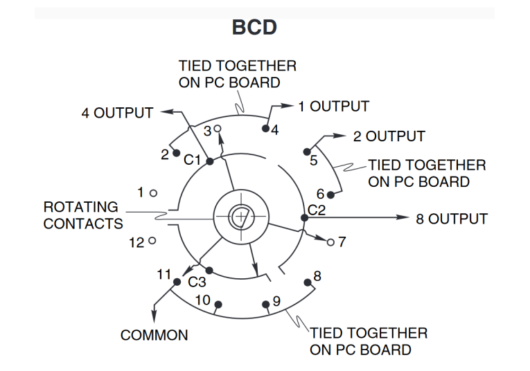
Figure 1 shows an exploded view of a BCD rotary switch, and Figure 2 shows the equivalent schematic. In Figure 2, the switch drawing is viewed from the front and is shown in switch position number 1, which is decimal number 0 and BCD number 0. The solid circles have a terminal present, where the hollow circles do not.

Serial Communications
As useful as BCD coding is for switches, an even more efficient method to minimize wiring is to use serial communications. With this method, digital data bits are sent one after the other down a single pair of wires. In the early days of personal computers, parallel printers were connected using 25-pin connectors having separate wires for each of the 8 bits of data being sent. Other wires served such tasks as handshaking, so the printer could tell the computer to pause sending until the printer was ready to receive more data. Back then memory was very expensive, so printers could hold only a page or two of text in their receive buffer.
Likewise, computer sound cards back then were plugged into multi-pin connectors on the motherboard to transfer 16 bits of data on 16 separate connections. Today printers and sound cards, and many other devices (e.g., scanners and external hard drives) connect using USB, which is also a serial protocol. Of course, serial communication requires a much faster transmission rate than parallel because the bits are sent one after the other rather than all at once. Plus, the devices at both ends need additional circuitry to encode and decode the serial data stream. So BCD is still useful for simple passive components (e.g., switches).
Rotary and Up/Down Encoders
From the user’s perspective, a rotary encoder is similar to a rotary switch. But instead of a fixed number of positions, the knob continuously rotates. An incremental rotary encoder merely outputs a series of pulses as the knob is turned, where the absolute type of encoder outputs the current knob position. There are many sub-types within these broad categories, and also several construction materials (e.g., mechanical, magnetic, and optical).
So I’ll just cover the basics. The main feature of rotary encoders is that they can accommodate dozens or even hundreds of positions efficiently, and with only a few connecting wires. Up/Down encoders serve a similar function, but use a pair of push button switches instead of a rotating knob.
The only thing an incremental encoder needs to do is output a signal to show that the knob is being turned, and also indicate the direction of rotation. Incremental encoders are common in applications where there are too many positions for a conventional rotary switch to handle. For example, most modern hi-fi and home theater receivers control the volume digitally, typically with 90 or more steps in 1dB increments.
Years ago, I owned a Yamaha SY-77 synthesizer containing more than 100 musical instrument sounds. That too used a rotary encoder to scroll through all of the patch names on a small LCD display. It’s not practical to build a switch with that many positions, so the knob of a rotary encoder will complete several rotations as you adjust the volume over a large range. But unlike a rotary switch, when the power is turned off then on, the previous setting is not available. So it’s up to the receiver or other device to remember the last volume setting.
Likewise for Up/Down switches. In contrast, the current position of an absolute encoder is always available. Like the BCD switches described earlier, absolute rotary encoders also output a binary number to indicate a large number of positions with fewer connections.
When many positions are used, the host software can optionally be written to detect if you’re quickly spinning the dial, for example to increment by tens instead of single digits. Up/Down switches can be handled the same way when there are many possible steps. To set the Clock on my kitchen oven I press Clock, then the Up or Down buttons that normally set the oven temperature. Pressing the Up button once increments the time by one minute. Pressing and holding the button for one second advances the time fairly quickly. Continuing to press for two more seconds advances the time much more rapidly.
I realize this is pretty basic stuff, but writing the software that reads these encoders and buttons and changes the timing as described is fairly complex.

Matrix Addressing
Another clever example that reduces the cost of long wire runs is found inside pinball machines. Most games have a playfield containing many dozens of lights, and just as many switches, all which must be controlled and read independently by the computer that manages play. Each bulb or switch has two contacts, and with conventional wiring all of the common grounds are connected. So one ground wire can snake through all the light bulb sockets connecting their ground side, and another ground wire can serve all the switches. But that still leaves a lot of separate wires needed for all of the switch and light bulb “hot” terminals. Even more relevant, computer chips don’t have 100 or more extra output terminals to control that many lights and switches individually. With matrix addressing, as many as 64 light bulbs can be controlled by only 16 signal wires, and up to 64 switches can be read the same way.
Instead of running separate wires from the computer controller to every switch and light bulb, a matrix system of Rows and Columns is used. Figure 3 shows a portion of the schematic for my 1980s vintage Fire Power pinball machine. This section details the matrix that controls all of the light bulbs, and another similar section (not shown) reads all of the switches. To address the light bulbs individually, the rows and columns are strobed (activated in sequence) with only one row and one column active for a few milliseconds at a time. When several bulbs are to illuminate, each is activated in sequence, but this happens so quickly that all the bulbs appear to be illuminated at once. Diodes are placed in series with each bulb to avoid interaction between the bulbs.

Reading a matrix of switches is similar, where the CPU continuously polls each switch very quickly in sequence. Even with all the additional electronics needed to implement matrix addressing, it’s still less expensive to manufacture than using the additional wire, connectors, hand labor, and computer controller chips. Two of my pinball machines are 40 years old, and sometimes the circuit board connectors become flaky. One side benefit of the matrix is that when one entire row or column goes out on my machines, it’s easy to tell which circuit board connector pin needs to be pushed in more tightly.
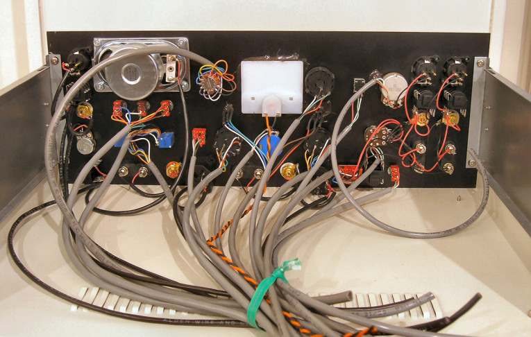
Photo 3 shows the lower cabinet interior of Fire Power, with the playfield lifted to see its underside. The wire bundles at the bottom of the photo are coming down from the power supply and driver board inside the upper cabinet behind the painted glass. These wires connect to all the light bulbs and switches on the playfield, and to other electromechanical components such as the flippers and ball kickers. Without matrix addressing even more wires would be needed, and those wire bundles would be three times thicker. aX
This article was originally published in audioXpress, March 2021
Resources
E. Winer, “Building a Null Tester Device,” audioXpress, June 2019,
Ethan’s own website | ethanwiner.com
RealTraps | realtraps.com