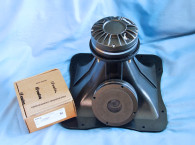
The NMF dome tweeters (the T-25M and the T-25S) were featured in the December 2022 issue of Voice Coil, designed by Beyma’s newest engineer Diego Ivars (formerly a SEAS transducer engineer). The NMF line also incorporates three woofers with a similar feature set that includes carbon fiber cones and dust caps, Malt Cross cooling technology, triple aluminum and copper shorting rings, dual Bimax spiders, and Quattro inside/outside voice coil windings! This includes the 6.5” 6NMFW midbass driver, the 8” 8NFMW midbass driver, and the subject of this Test Bench explication, the 10” 10NMFS subwoofer shown in Photo 1.
Features for the 10” 10NMFS subwoofer are substantial, which is interesting considering the NMF drivers are not PA drivers, but studio/home monitor transducers. Starting with the frame, the Beyma 10NMFS uses a proprietary five fairly wide twin spokes in an octagonal-shaped cast aluminum frame.
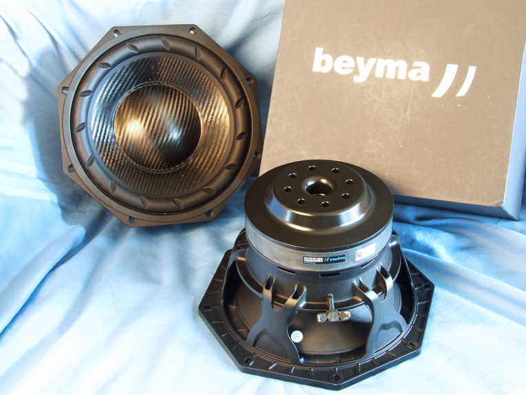
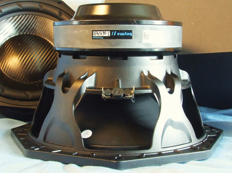
The cone assembly consists of a curvilinear profile carbon fiber cone and a 4.5” diameter carbon fiber dust cap. Compliance is from a convex roll articulated NBR surround. The slanted articulations appear as out-of-phase bucking at long excursions. Remaining compliance comes from a double Bimax 6.5” diameter flat spider. Tinsel leads are stitched into the spider for long-term stability and attached to solderable terminals.
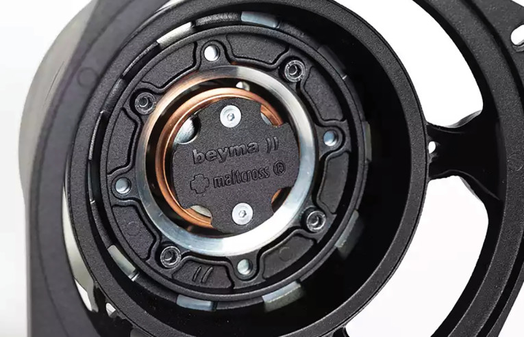
The motor design on the Beyma 10NMFS utilizes a FEA-optimized ceramic (ferrite) magnet structure driving a 63.5mm (2.5”) diameter voice coil wound with round copper wire on a non-conducting former with Beyma’s QUATTRO inside/outside winding configuration. Motor parts, the return cup, and the front plate are coated with a black heat-emissive coating for improved cooling. Integral to this motor is an aluminum demodulation ring (shorting ring aka Faraday shield), which is part of the Malt Cross cooling technology plus two copper shorting rings for distortion reduction.
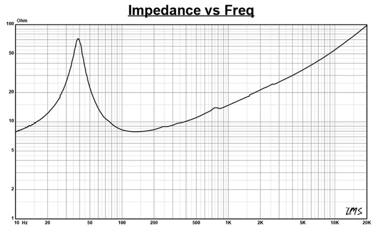
I commenced testing the Beyma 10NMFS 10” subwoofer using the LinearX LMS analyzer and the Physical LAB IMP Box (the same type test fixture as a LinearX VI Box, used for measuring voltage and current separately) to create both voltage and admittance (current) curves. With the driver clamped to a rigid test fixture in free air at 0.3V, 1V, 3V, 6V, 10V, 20V, and 30V, I allowed the voice coil to progressively heat up between sweeps. The Beyma driver remained sufficiently linear enough for LEAP 5 to curve fit the impedance at the 30V level, and probably would have stayed linear up to at least 40V in free air.
Following my established protocol for Test Bench testing, I no longer use a single added mass measurement and instead use the manufacture supplied Mmd data (84.9 grams for the Beyma 10NMFS). I post-processed the 14 550-point stepped sine wave sweeps for each 10NMFS sample and divided the voltage curves by the current curves to generate impedance curves, with the phase derived using the LMS calculation method.
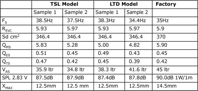
I imported the data, along with the accompanying voltage curves, to the LEAP 5 Enclosure Shop software. Because Thiele-Small (T-S) parameters provided by the majority of OEM manufacturers are generated using either the standard model or the LEAP 4 TSL model, I additionally created a LEAP 4 TSL parameter set using the 1V free-air curves. I selected the complete data set, the multiple voltage impedance curves for the LTD model, and the 1V impedance curve for the TSL model in the Transducer Model Derivation menu in LEAP 5 and created the parameters for the computer box simulations. Figure 1 shows the 1V free-air impedance curve. Table 1 compares the LEAP 5 LTD and TSL data and factory parameters for both Beyma 10NMFS samples.
Following my established measurement protocol, I configured computer enclosure simulations using the LEAP LTD parameters for Sample 1. I programmed two computer box simulations into LEAP 5, an Extended Bass Shelf (EBS) vented box alignment with a 1.15ft3 volume (15% fiberglass fill material) tuned to 35Hz and a smaller sealed enclosure with 0.57ft3 volume simulated with 50% fiberglass damping material.
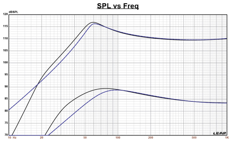
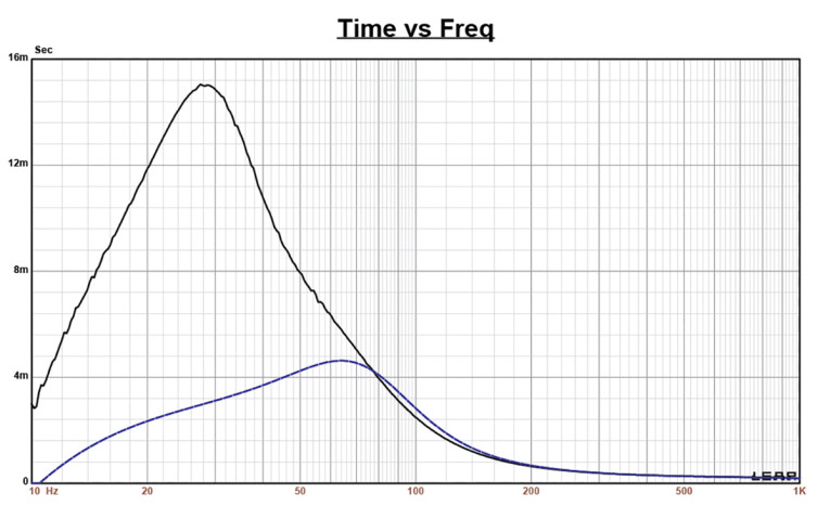
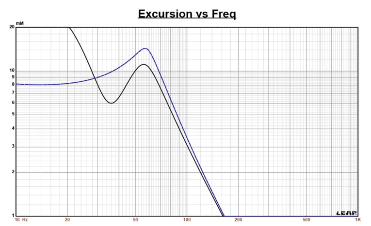
Figure 2 displays the SPL results in the vented and sealed enclosures at 2.83V and at a voltage level sufficiently high enough to increase cone excursion to Xmax+15% (14.4mm for the 10NMFS). This produced an F3 frequency of 45Hz (F6=36Hz) for the EBS vented box and -3dB=61Hz (F6=50Hz) Qtc=0.71 for the smaller sealed enclosure simulation. Increasing the voltage input to the simulations until the maximum linear cone excursion limit was reached resulted in 117dB at 90V input for the vented box and 116.5dB for a 98V input level for the smaller closed box. Figure 3 shows the 2.83V group delay curves. Figure 4 shows the 90V/98V excursion curves. Please note that the 10NMFS starts over excursing below 25Hz in the vented simulation, so an appropriate high-pass filter will increase the undistorted output considerably.
Klippel analysis for the 10” NMF subwoofer, performed this month by Warkwyn (Jason Cochrane did the analysis on the KA3 analyzer), produced the Bl(x), Kms(x), and Bl and Kms symmetry range plots given in Figures 5-8. The Bl(x) curve for the 10NMFS (Figure 5) is moderately broad and exhibits a degree of offset, tilt, and asymmetry to the curve, but is not at all so extensive as to be a deal breaker. Looking at the Bl symmetry plot (Figure 6), by the time this curve reaches a position of high certainty between 8mm-10mm, the offset has dropped 0.43mm coil-in (rearward) offset. At the 12.5mm physical Xmax position, the offset is reversed to a likewise small 0.43mm coil-out (forward) offset. This minor offset remains >0.8mm out to at least 15.5mm, so not at all a major issue.
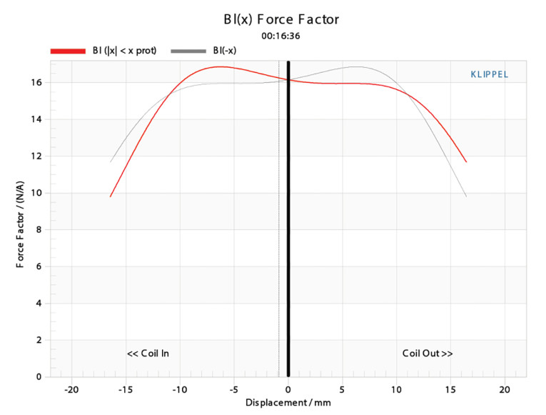
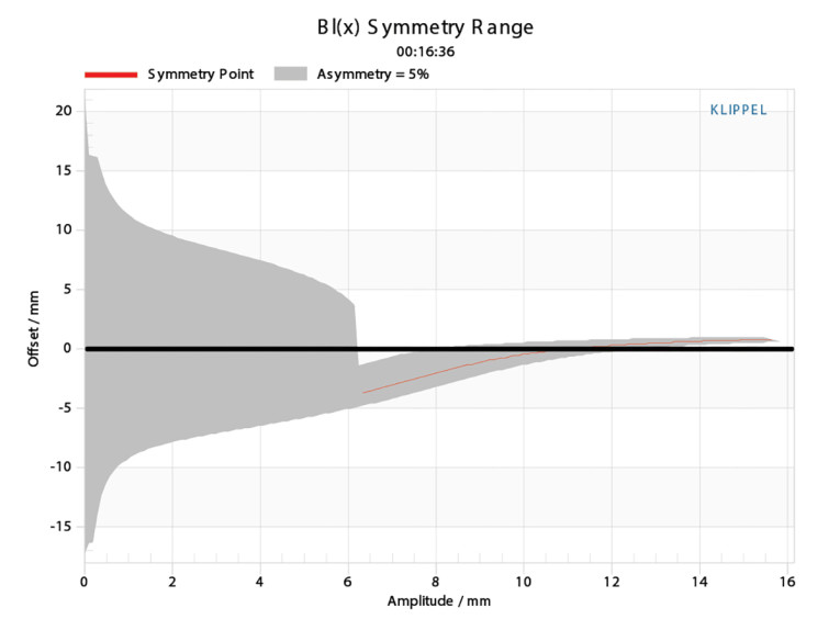
Figure 7 and Figure 8 show the Kms(x) and Kms symmetry range curves for the Beyma 10NMFS. The Kms(x) curve is also moderately symmetrical in both directions accompanied by a very small amount of coil-in (rearward) offset. Looking at the Kms symmetry range plot, the coil-out offset at the physical 12.5mm physical Xmax of the driver is 0.83mm coil-in. Displacement limiting numbers calculated by the Klippel analyzer for the 10NMFS were XBl @ 70% Bl=15.21mm and for XC @ 50% Cms minimum was >16.54mm, which means that for this Beyma 10” driver, the Bl is the most limiting factor for prescribed distortion level of 20% (the criteria for subwoofers). Both numbers are, however, greater than the physical Xmax of the 10NMFS.
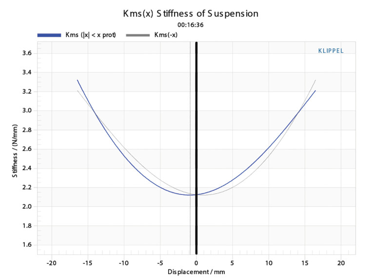
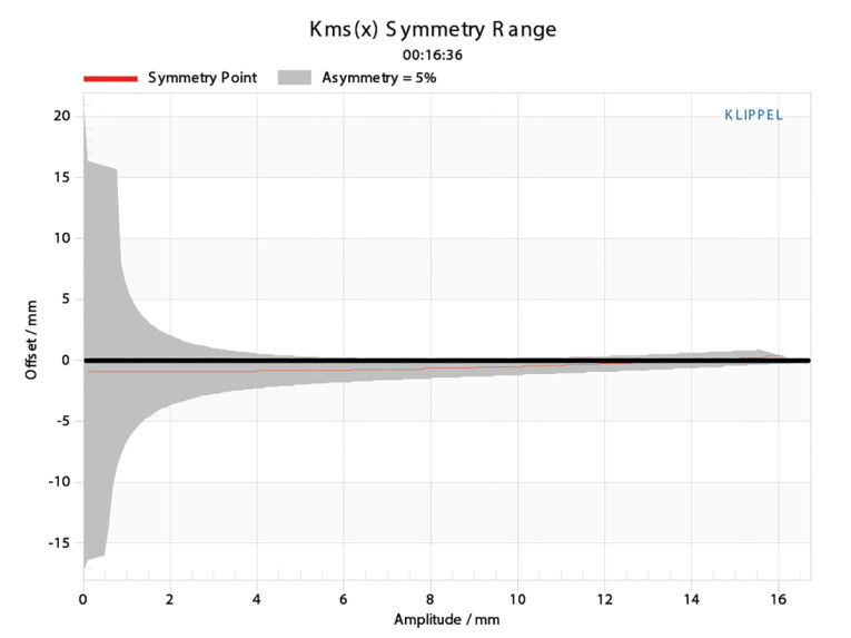
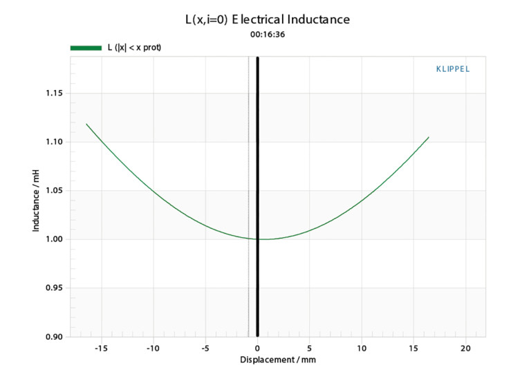
Figure 9 gives the inductance curves Le(x) for the 10NMFS. Inductance will typically increase in the rear direction from the zero-rest position as the voice coil covers more pole area, which is not what is happening here, but is typical of this type of motor that incorporates multiple aluminum/copper demodulation (shorting) rings. The maximum inductance swing for this driver from Xmax in to Xmax out is a low 0.074mH maximum, which is excellent performance for this powerful (Bl=16Tm) ferrite motor.
Since the 10NMFS is designated as a subwoofer, I would expect it be crossed over between 100Hz to 200Hz. As per my usual Test Bench protocol, I do not provide SPL data on subwoofers, but only publish the factory SPL measurements shown in Figure 10. The 1W/1m plot shows the 10NMFS at 0° on-axis and 45° off-axis.
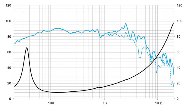
Given the SPL anomaly centered on 8kHz, this driver could easily be crossover to a midrange driver between 200Hz to 700Hz so it could easily be used in a three-way application as well as a subwoofer.
Last, I employed the Listen SoundCheck AudioConnect analyzer and SCM microphone to measure distortion. Note that like SPL and polar plots, I do not generate time-frequency plots for subwoofer transducers.
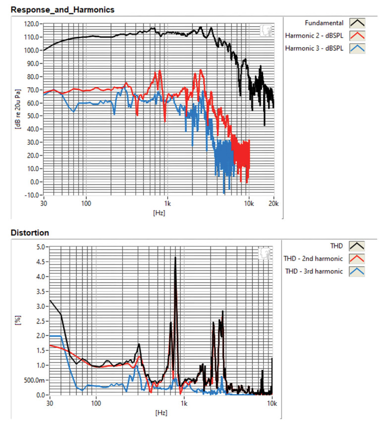
For the distortion measurement, I mounted the 10” driver rigidly in free air and set the SPL to 94dB (the criteria for home/studio monitor drivers) at 1m (9.7V), using SoundCheck’s built-in pink noise generator and SLM. I then measured the distortion with the Listen microphone placed 10cm from the driver. This produced the distortion curves shown in Figure 11.
Looking at the objective data gathered on this 10” transducer, the 10NMFS, like all the transducers from Beyma that have been explicated in Test Bench, looks to be a very well-crafted driver with a good set of performance trade-offs, not to mention the world-class Beyma Malt Cross cooling system technology. For more information, visit www.beyma.com. VC
This article was originally published in Voice Coil, August 2023.