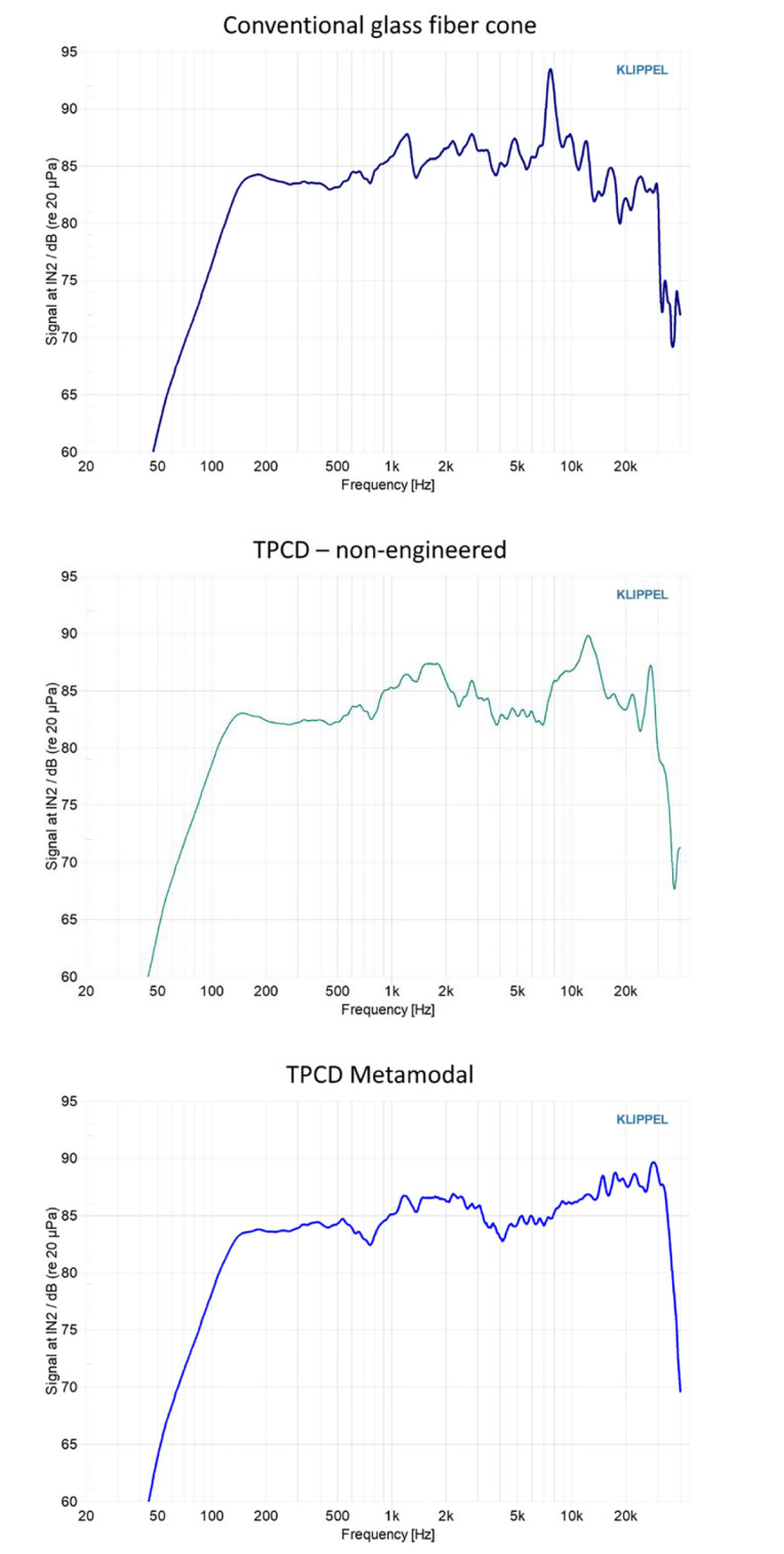
Metamaterial is any material engineered to have a property that is rarely observed in naturally occurring materials. Martin Turesson, head of Composite Sound, originally wrote about the metamodal process as applied to diaphragm technology in the February 2022 issue of Voice Coil magazine, and again recently in an article titled “TPCD Technology in Headphones: Engineering to Control Diaphragm Resonances” published in the January 2024 issue of audioXpress. As applied to TPCD diaphragms, this means that by judiciously adjusting the location of weight and thickness in the diaphragm, you can control the cone modes and resonances.
Figure 1 shows three SPL curves: curve (a) is the frequency response of a conventional glass fiber cone, curve (b) is the frequency response of similarly constructed TPCD cone without and metamodal engineer of the material, and curve (c) is the frequency response of an engineered TPCD metamodel cone. The benefits of controlling resonant break-up modes are obvious.
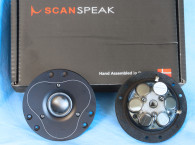
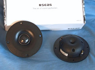
SEAS participated in the early stages of the TPCD metamodal process, and as a result has recently released the first two TPCD metamodal drivers in the industry — the new SEAS Excel T29X001 tweeter featured in the March issue of Voice Coil Test Bench, and the subject of this Test Bench explication the new SEAS Excel W16NX005 midbass woofer.
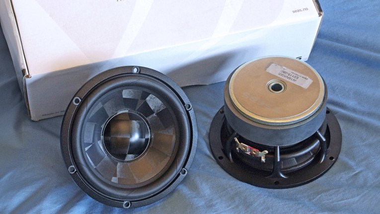
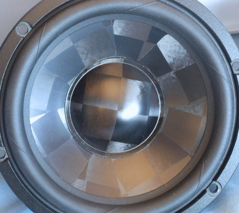
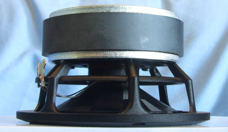
Features for the W16NX005, shown in Photos 1–3, has a generous feature set that includes a proprietary six-spoke cast-aluminum frame. Like many high-end midbass drivers, the spokes are narrow and tapered (8.6mm to 5.3mm wide) thus providing minimum reflections into the rear cone surface, plus the frame is substantially open below the spider (damper) mounting shelf for voice coil cooling.
Other features include the second-generation TPCD metamodal diaphragm with 2” diameter metamodal convex dustcap, along with an optimized NBR surround and 3.75” diameter black cloth flat profile spider for compliance. The TPCD-based cone assembly is driven by a 39mm (1.53”) diameter two-layer voice coil wound with round copper-clad aluminum wire (CCAW) wire on a Titanium non-magnetically conducting former. Powering the CCAW wound Titanium former is an FEA-optimized motor structure that incorporates a 110mm×25mm ceramic magnet, a set of dual shorting rings above and below the gap area that reduce distortion caused by eddy currents, and an 11mm diameter pole vent for additional cooling. Last, the braided voice coil lead wires terminate to a pair of gold-plated solderable terminals.
I commenced characterizing the new W16NX005 5.25” midbass woofer using the LinearX LMS analyzer and the Physical LAB IMP Box (the same type of test fixture as a LinearX VI Box for measuring voltage and current separately). Sweeps were generated with the driver securely mounted in free air at 0.3V, 1V, 3V, 6V, 10V, and 15V. The measured Mmd was used rather than a single 1V added (delta) mass measurement. It should also be noted that this multi-voltage parameter test procedure includes heating the voice coil between sweeps for progressively longer periods to simulate operating temperatures at that voltage level (raising the temperature to the first- and second-time constants). The 15V curves were sufficiently linear to get an adequate curve fit and were incorporated into the Thiele-Small (T-S) parameter routine, which is impressive for a 5.25” woofer.
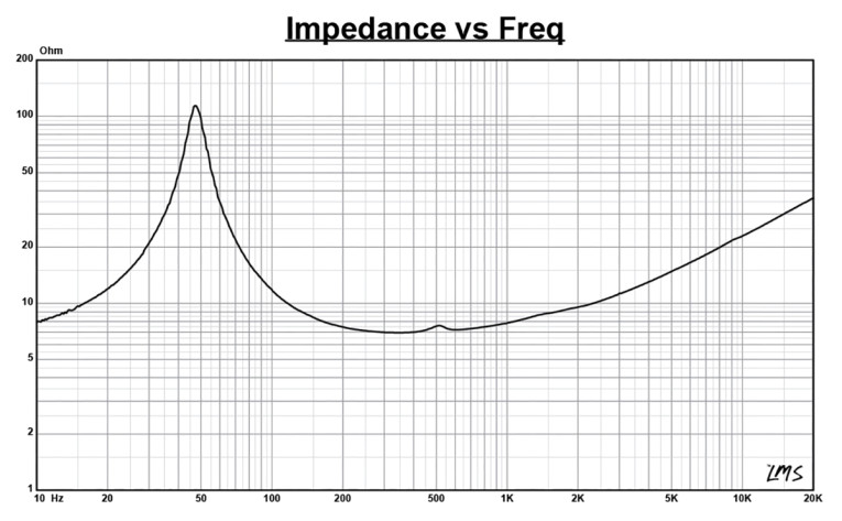
The 12 stepped sine wave sweeps for each woofer were further processed with the voltage curves divided by the current curves to produce impedance curves. Phase curves were generated using the LEAP phase calculation routine, after which the impedance magnitude and phase curves plus the associated voltage curves were then copy/pasted into the LEAP 5 Enclosure Shop software’s Guide Curve library. This data was then used to calculate parameters using the LEAP 5 LTD transducer model. Because most all manufacturing data is being produced using either a standard transducer model or in many cases the LEAP 4 TSL model, I also generated LEAP 4 TSL model parameters using the 1V free air that can also be compared with the manufacturer’s data. Figure 2 shows the 1V free air impedance plot. Table 1 compares the LEAP 5 LTD and LEAP 4 TSL T-S parameter sets for the SEAS W16NX005 midbass driver samples along with the SEAS factory data.
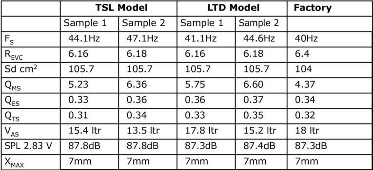
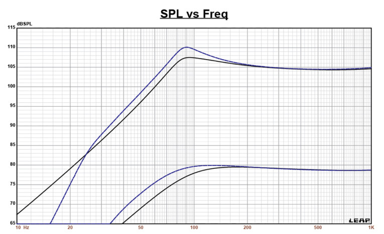
From the comparative data shown in Table 1 for the 5.25” W16NX005 midbass woofer, you can see that all four parameter sets for the two samples were reasonably similar and correlated rather well with the factory data. Following my normal protocol for Test Bench testing, I used the sample 1 LEAP 5 LTD parameters and set up two computer box simulations, one in a 278in3 Butterworth-type sealed enclosure (Qtc=0.7) with 50% fill material (fiberglass). The second simulation was a vented Extended Bass Shelf (EBS) alignment in a 409in3 box with 15% fill material and tuned to 45Hz.
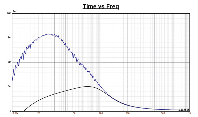
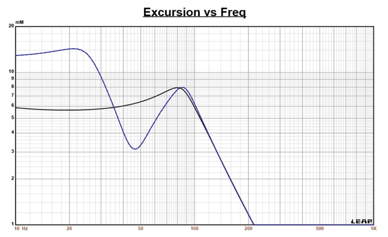
Figure 3 gives the enclosure simulation results for the SEAS W16NX005 midbass driver in the sealed and vented enclosures at 2.83V and at a voltage level sufficiently high enough to increase cone excursion to Xmax+15% (8.1mm for W16NX005). This resulted in an F3 of 84Hz (-6dB=64Hz) with a Qtc=0.68 for the 278in3 closed box and a -3dB for the vented simulation of 67Hz (-6dB=53Hz). Increasing the voltage input to the simulations until the approximate Xmax+15% maximum linear cone excursion point was reached resulted in 107.5dB at 33V for the sealed enclosure simulation and 110dB with a 34.2V input level for the larger vented box. Figure 4 shows the 2.83V group delay curves and Figure 5 shows the 33V/34.2V excursion curves.
The Bl(X) curve for W16NX005 (Figure 6) is moderately broad and symmetrical typical of a high Xmax 5.25” to 6” woofer, and with a small amount of offset. The Bl symmetry curve (Figure 7) shows a small 0.58mm Bl coil-out (forward) offset once you reach an area of reasonable certainty around 4mm, increasing to 0.84mm at the physical 7.0mm Xmax position, so relatively minor.
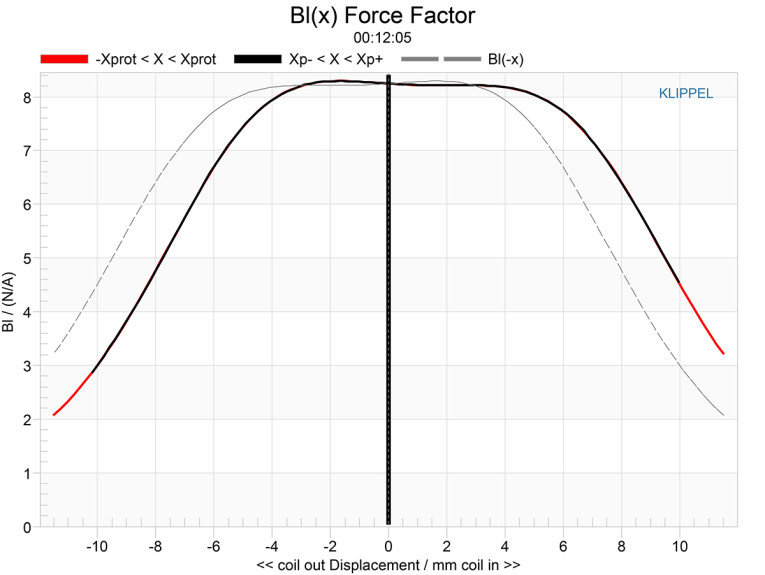
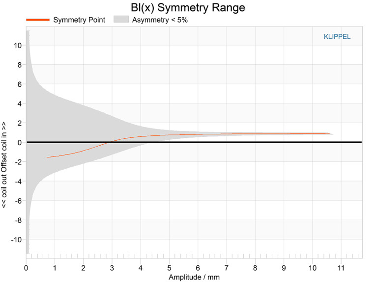
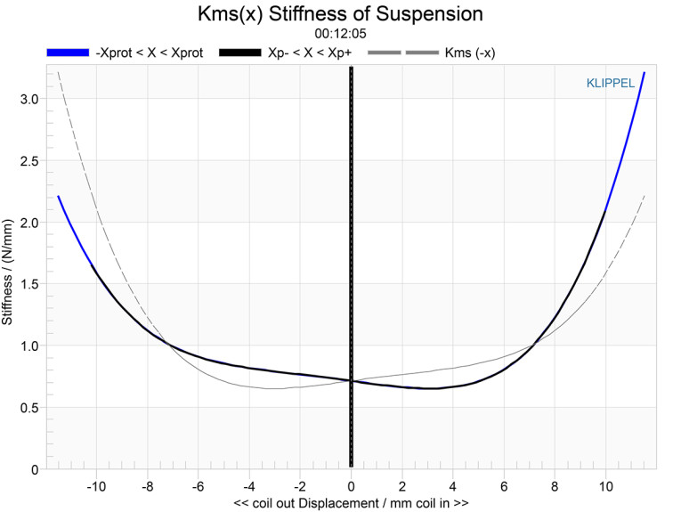
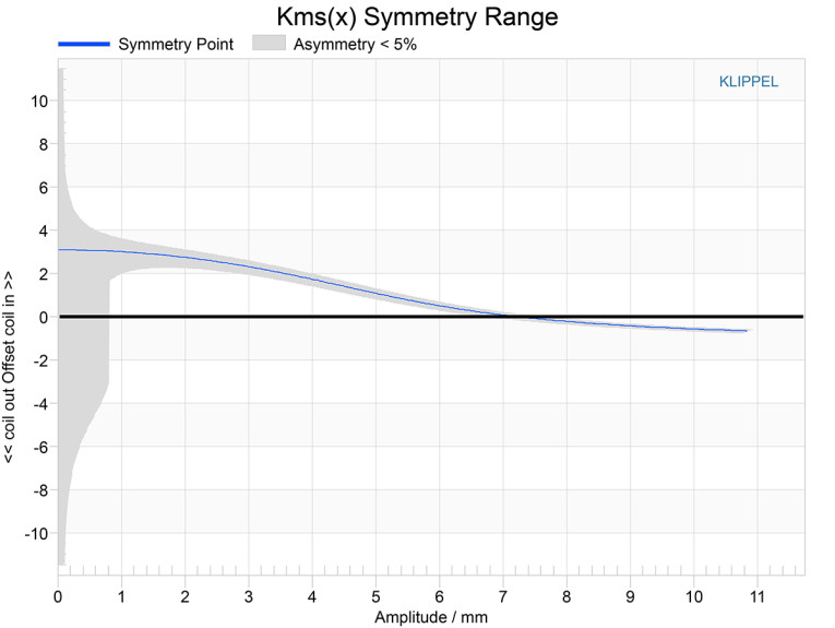
Figure 8 and Figure 9 show the Kms(X) and Kms symmetry curves for the SEAS TPCD midbass. The Kms stiffness of compliance curve (Figure 8) is not quite as symmetrical as the Bl curve and accompanied by a degree of “tilt.” The Kms symmetry range curve (Figure 9) indicates a 2.7mm forward (coil-out) offset at a point of reasonably certainty at 2mm, progressively decreasing to zero offset at physical 7.0mm Xmax position.
Displacement limiting numbers calculated by the Klippel analyzer for the W16NX005 for Bl was XBl @ 82% (Bl dropping to 82% of its maximum value) equal to 5.9mm for the prescribed 10% distortion level (the criterion for full-range drivers). For the compliance, XC @ 75% Cms minimum was 6.6mm, which means that for the SEAS 5.25” woofer, the Bl is the more limiting factor for getting to the 10% distortion level. If we use the more conservative 20% distortion criteria, which is a number a lot of practitioners I know think is appropriate for midbass drivers as well as subwoofers, then the displacement limit numbers are XBl=7mm and XC=8.6mm, both numbers equal to or greater than the physical Xmax of the W16NX005.
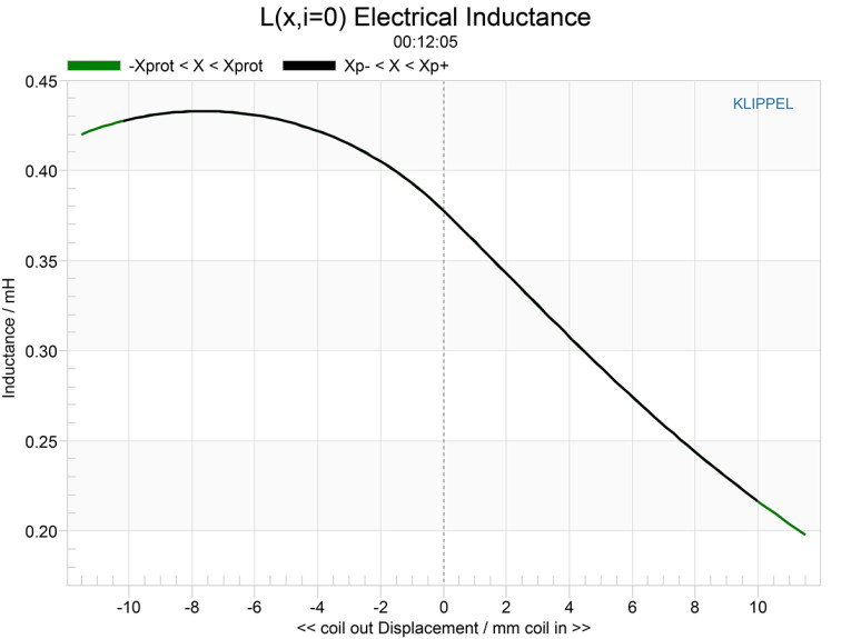
Figure 10 gives the inductance curve Le(X) for the SEAS W16NX005. Motor inductance will typically increase in the rear direction from the zero-rest position as the voice coil covers more of the pole, which mostly happens in this situation. However, due to the implementation of a dual shorting ring configuration what you do get is lower inductance variation from full in to full out travel, which is the goal you want to achieve. It’s easy to see the benefit of the dual shorting rings with inductance only varying only 0.175mH from Xmax in to Xmax out, which is very minimal inductance change and indicates excellent inductive performance.
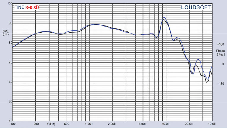
With the Klippel testing completed, I mounted the SEAS W16NX005 woofer in a foam-filled enclosure that had a 15”x6” baffle and then measured the device under test (DUT) using the Loudsoft FINE R+D analyzer and the GRAS 46BE microphone (courtesy of Loudsoft and GRAS Sound & Vibration). Both on- and off-axis from 200Hz to 20kHz at 2V/0.5m were normalized to 2.83V/1m using the cosine windowed FFT method. Figure 11 gives the W16NX005’s on-axis response indicating a smooth ± 2.5 response from 300Hz to 7.9 kHz, with a break-up mode centered on about 9.2kHz.
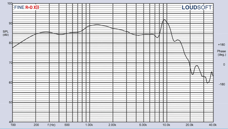
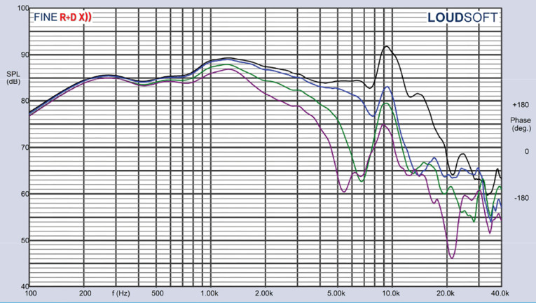
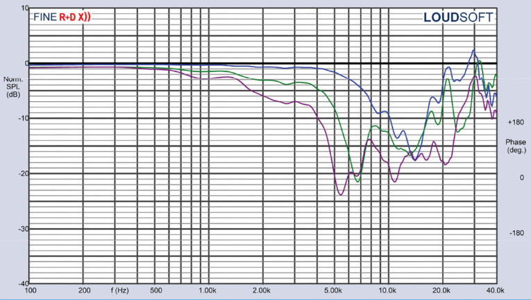
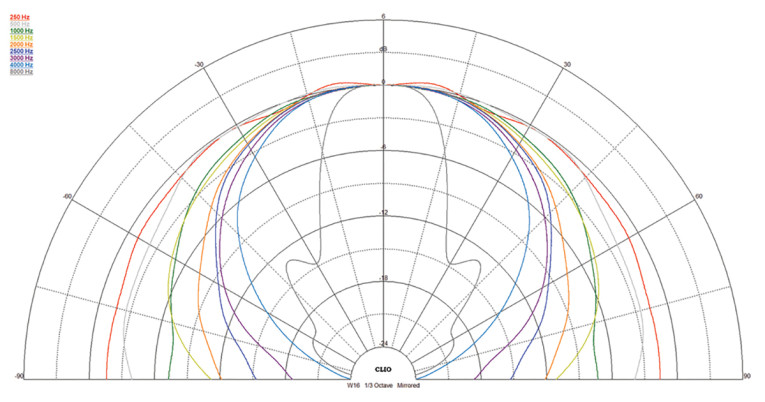
Figure 12 displays the on- and off-axis frequency response at 0°, 15°, 30°, and 45°, showing the typical directivity for a 5.25” to 6” woofer. The -3dB at 30° with respect to the on-axis curve occurs at about 2.3kHz, so 2.3kHz to 2.8kHz is a reasonable frequency for a low-pass crossover to produce a good power response. The normalized version of Figure 12 is given in Figure 13. Figure 14 shows the CLIO polar plot (in 10° increments and 1/3 octave smoothing). And finally, Figure 15 displays the two-sample SPL comparisons for the 5.25” SEAS TPCD driver, showing a very close match ≤0.9dB throughout the operating range.
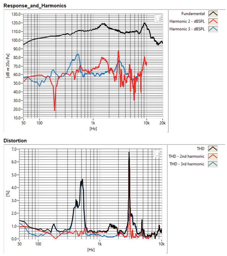
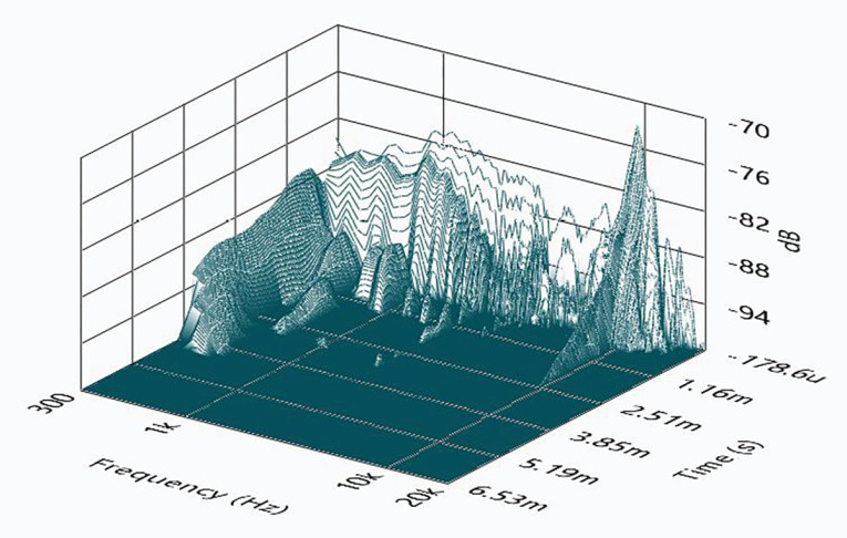
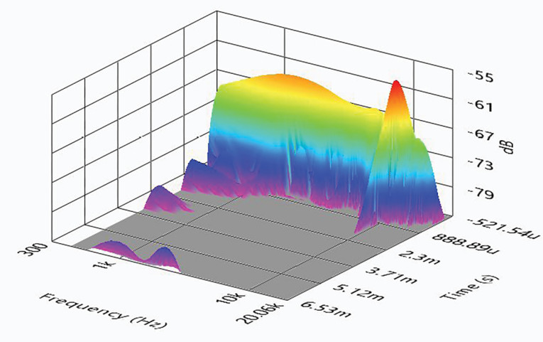
For the last remaining series of tests on the W16NX005 TPCD woofer, I again initialized the Listen SoundCheck AudioConnect analyzer and SCM ¼” microphone (courtesy of Listen, Inc.) to measure distortion and generate time-frequency plots. For the distortion measurement, the 5.25” SEAS W16NX005 driver was mounted rigidly in free-air, and the SPL set to 94dB at 1m (7.1V) using a pink noise stimulus. Then, I measured the distortion with the Listen microphone placed 10cm from the driver. This produced the distortion curves shown in Figure 16, with third-harmonic distortion staying primarily between 0.2% to 0.4% from 100Hz to 6.2kHz.
This article was originally published in Voice Coil, April 2024


