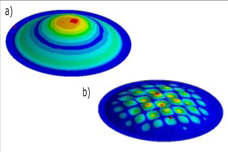
By optimizing the way the thin-ply carbon layers are organized, mechanical performance can be maximized, weight minimized, and, the part can be engineered to behave in certain desired ways in different areas and different directions. By optimizing the fiber architecture, the symmetric break up modes are replaced with more but smaller and local break up modes (see Figure 1 for a break-up mode comparison between a Titanium and Textreme compression driver diaphragms). This creates a distributed break up with smaller peaks in the frequency response and ultimately a smoother and more natural sound without harshness. Due to the ultralight weight and very high stiffness, high frequency diaphragms are also made using thin-ply carbon technology.
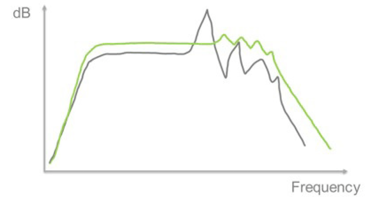
The effect on the frequency response curve is shown in Figure 2. The big peaks of the hard diaphragm (e.g., titanium or aluminum) in gray are replaced with more but smaller peaks in the thin-ply carbon diaphragm in green. Furthermore, higher stiffness to density ratio as well as the distributed break up is shown as the break up is moved up in frequency. The lower moving mass of the thin-ply carbon diaphragm results in higher sensitivity.
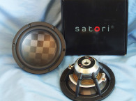
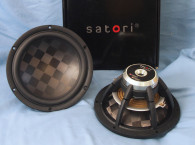
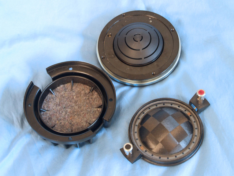
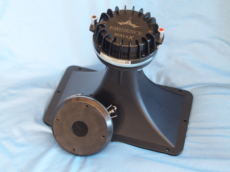
Designed for use with 1.4” throat horns, the N314X compression driver has a 35.6 mm (1.4”) throat diameter driven by a 76.2 mm (3”) diameter voice coil wound with round copper-clad aluminum wire (CCAW) on a nonconducting polyimide former driving a TeXtreme diaphragm and PEN surround (see Photo 1). The N314X also incorporates a three-slot annular phase plug and an acoustically damped black die-cast aluminum cover with heatsink fins.
Other features include a FEA-optimized neodymium magnet motor structure, a continuous power handling of 300 W with a 75 W (AES) power handling rating, a 800 Hz recommended crossover frequency (with a minimum 12 dB/octave high-pass network), and 1 W/1 m 110.5 dB sensitivity (average output across the operational frequency range). Along with the N314X, I used an Eminence 1.4” H14EA 60° × 40° exponential horn with a 600 Hz cut-off frequency (see Photo 2). The H14EA has been previously featured in Test Bench, so I will only show horizontal frequency response measurements, but just in case you are curious, I am providing both horizontal and vertical polar plots.


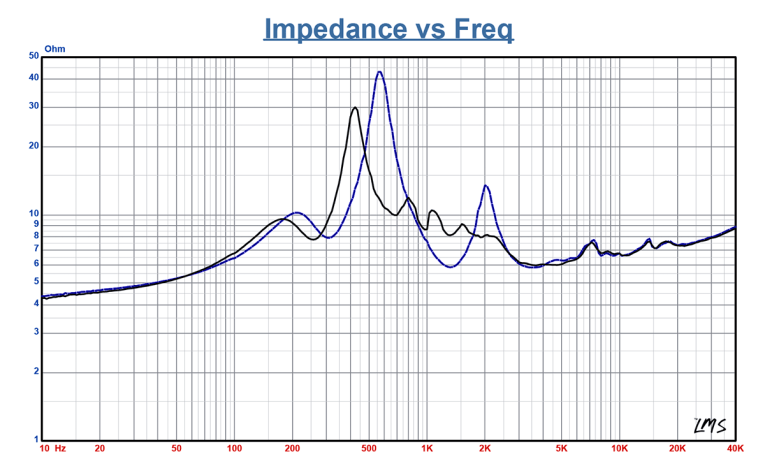
I commenced testing using the LinearX LMS analyzer to produce the 300-point stepped sine wave impedance plot shown in Figure 3, with the solid black curve representing the N314X mounted on the H14EA horn and the dashed blue curve representing the compression driver without the horn. With a nominal 8 Ω impedance, the N314X has a 5 Ω DCR, with minimum impedance mounted on the H14EA horn of 5.99 Ω and at 3.68 kHz.
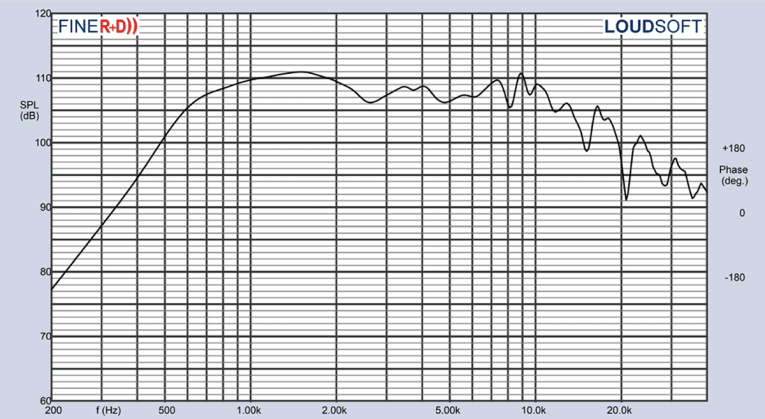
For the next set of SPL measurements, I free-air mounted the N31X/H14EA combination without an enclosure and measured both the horizontal on- and off-axis at 2 V/0.5 m (normalized to 2.83 V/1 m) from 0° on-axis to 60° off-axis using the LoudSoft FINE R+D analyzer and the GRAS 46BE microphone (supplied courtesy of LoudSoft and GRAS Sound & Vibration). Figure 4 displays the on- axis frequency response of the compression driver/horn combination, which is relatively smooth ±3 dB with no major anomalies from the 800 Hz recommended crossover frequency to about 13 kHz, beginning its second-order low-pass roll-off between 10 kHz to 40 kHz.
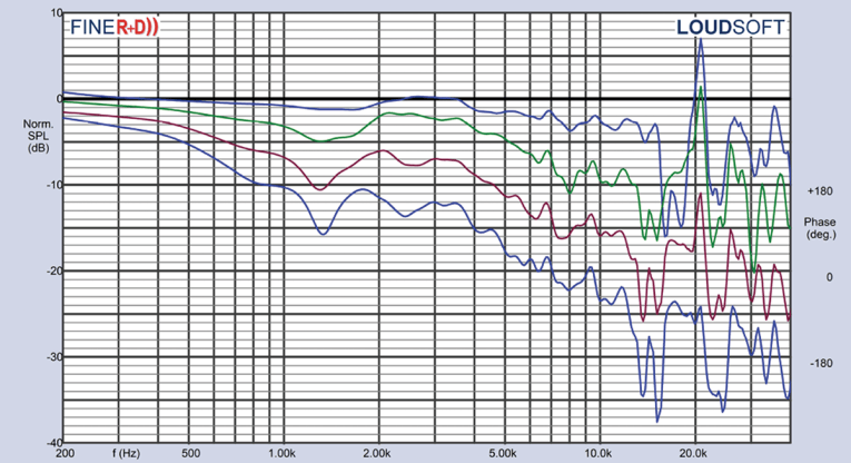
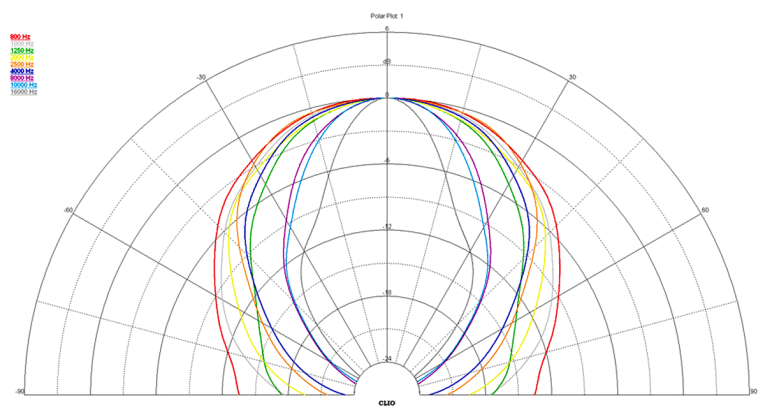
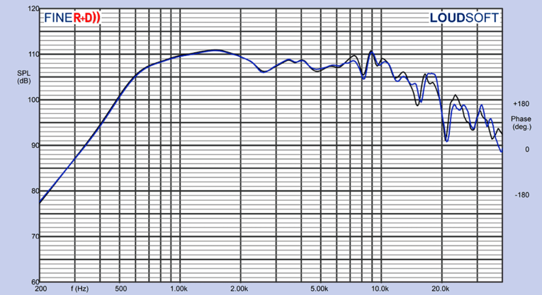
Figure 5 shows the 0° to 60° on and off-axis response in the horizontal plane. Figure 6 shows the normalized horizontal plane response. Figure 7 shows the 180° horizontal polar plot (in 10° increments with1/3 octave smoothing applied), generated by the CLIO Pocket analyzer and accompanying microphone (courtesy of Audiomatica SRL). Figure 8 shows the 180° vertical plane polar plot (also with 10° increments with 1/3 octave smoothing applied). Last, Figure 9 illustrates the two-sample SPL comparison showing the two Eminence Tour Grade N314X compression driver samples to be closely matched within 1 dB to 1.5 dB or less above the recommended crossover frequency 12 kHz, with somewhat greater variation above that, which is why most QC windows are wider above 10 kHz.


For the remaining series of tests, I again set up the Listen AudioConnect analyzer and 1/4” SCM microphone (provided by Listen, Inc.) to measure distortion and generate time-frequency plots. For the distortion measurement, I mounted the N314X/H14EA combination in free-air in the same manner as was used for the frequency response measurements, and set the SPL to 104 dB at 1 m (2.07 V determined by using a pink noise stimulus generator and internal SLM in the SoundCheck 17 software). Then, I measured the distortion with the Listen microphone placed 10 cm from the mouth of the horn. This produced the distortion curves shown in Figure 10. Note the extremely low third-harmonic level.
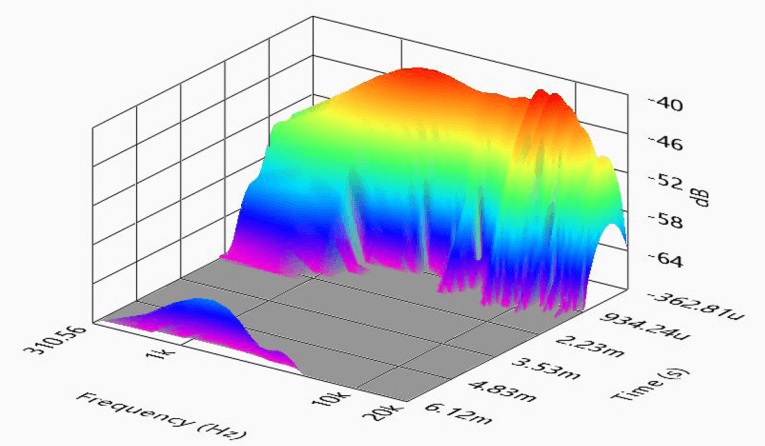
For the final test sequence, I set up SoundCheck 17 to generate a 2.83 V/1 m impulse response curve for the N314X/H14EA combination and imported the data into Listen’s SoundMap Time/Frequency software. Figure 11 shows the resulting cumulative spectral decay (CSD) waterfall plot. Figure 12 shows the Short Time Fourier Transform (STFT) plot.
Examining all the data, the Eminence Tour Grade N314X compression driver is obviously a well-engineered 1.4" compression driver, exhibiting good performance, great build quality, and uses a TeXtreme diaphragm! For more information about this compression driver and other great Eminence products, visit www.eminence.com. VC
This article was originally published in Voice Coil, May 2020.