On the original article published in audioXpress, Dennis Colin provided a complete review with measurements of the THOR project. His overall impressions stated: The speakers appear to reproduce whatever is fed them with flawless transparency. So well, they ruthlessly reveal any recording or medium deficiency.“ Colin also confirmed the impressive bass response. “These speakers don’t need any subwoofer, unless you need response down to 5Hz. (…) With these speakers, there was no audible separation or lack of coherence anywhere in the audio spectrum; the response in Joe’s room sounded flat down to 25Hz.”
For this online publication, audioXpress kept the original article unchanged, which has since been updated with availability of the original Madisound/SEAS kit and the publication of a complete kit project on SEAS own website. On a recent exchange with Joe D’Appolito, we asked him if he had considered revisiting the original project. Joe replied: “SEAS sponsored development of my THOR project, which used all SEAS drivers. I know it has become a popular speaker, but at present I have neither the time or resources to update the design. I believe the real contribution of the original THOR article was detailing the technique for experimental optimization of the Transmission Line.”
This article was originally published in audioXpress, May 2002
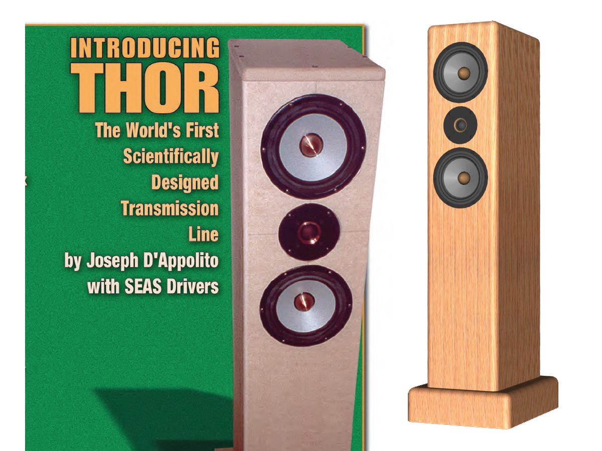
During CES 2000 I met with Norwegian and US representatives of SEAS. They described their new Excel line of drivers to me and asked whether I could design a flagship loudspeaker using these drivers that would highlight their extraordinary capabilities. They wanted something other than a vanilla sealed or vented box. I suggested a transmission line, pointing out that the non-resonant behavior of this enclosure assured that we would hear the full capabilities of these drivers free of “boxy” coloration. The SEAS folks agreed enthusiastically, and the THOR transmission-line project was born.
The THOR-Excel Transmission Line Loudspeaker Transmission-line (TL) loudspeakers have long enjoyed a small but dedicated following, especially in the DIY community. The advantages of TLs are well known. They are essentially non-resonant enclosures, producing a deep, well-controlled bass response. For a given driver, bass response can often extend well below that produced with either a vented or sealed enclosure using the same driver. Above a few hundred Hz, the line-filling material completely absorbs the driver back wave, giving the TL an open, non-boxy sound.
Unfortunately, the TL has not enjoyed wide commercial popularity due to the lack of a good design theory and the additional complexity of enclosure fabrication relative to the more conventional vented and sealed enclosures. Recently, however, work by G.L. Augspurger has appeared in the technical literature and in audioXpress (see References) that, while not providing a complete theory of design, has given us an excellent starting point. This, coupled with modern PC-based acoustic measurement systems, allowed me to converge quickly to an optimum design for the new Excel W18EX001 woofers.
The present design uses an MTM driver configuration in a tapered, folded line uniformly filled with Dacron pillow stuffing. Tapering the line greatly increases the frequency range of bass augmentation produced by the line. Using two mid-bass drivers exciting the line at slightly different points reduces mid-bass ripple. The resulting line produces a uniform 3–4dB bass response lift from 110Hz all the way down to 20Hz with less than 1dB ripple. The −3dB point is 44Hz. Contrast this against 65Hz for a similarly damped sealed enclosure. Below 45Hz TL bass response falls off at 12dB per octave, compared to the 24dB/octave falloff rate of a vented system. In most rooms useful bass response extends well down into the 30Hz region.
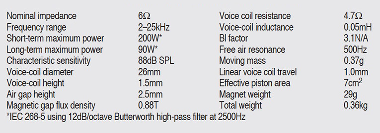
Above 2500Hz the system crosses over to an Excel T25CF002 tweeter. Several hundred hours of laboratory testing and listening have gone into producing a seamless transition between the mid-bass and tweeter drivers. You literally cannot tell where the woofers leave off and the tweeter begins. The Excel product line from SEAS was introduced in 1994 as a showcase for the company’s best ideas and technologies. Originally comprised of only five models, the Excel line has expanded to ten products, with additional designs in continuous development.
THE W18E001 Woofer
Building a “better” mid/woofer required a complete rethinking of nearly every component in the driver: the cone, the magnet system, the surround, and the basket.
The Magnesium Cone
The advantages of metal cones are well known. They remain virtually pistonic throughout their passband, and do not suffer from midband cone edge resonance problems so common in paper and other soft cones. Prior to the development of the magnesium cone, virtually all metal cones used some form of aluminum alloy. While aluminum is an easy material to form either by stamping or spinning, it also suffers from its share of acoustic drawbacks.
To keep the moving mass reasonably low, the cone must be quite thin. For an 18cm woofer, the nominal thickness is approximately .18mm. This, unfortunately, results in a cone with numerous high Q breakup modes starting at about 5kHz and extending beyond 10kHz. SEAS therefore decided to search for a material with a potential for greater stiffness than aluminum. Magnesium was attractive because its specific gravity was only 1.7 versus 2.7 for aluminum. This meant that, for the same cone mass, a magnesium diaphragm could contain almost 60% more material by volume than aluminum. This gave the potential for much greater stiffness and internal damping of the cone with no increase in mass. Acoustic testing of prototype magnesium cones immediately revealed the benefits over the aluminum cone: the breakup modes had been largely reduced to a single, well defined peak that could easily be suppressed via simple notch filtering.
The question was how to produce the cone? Magnesium does not lend itself to bending or shaping in the thickness required for a loudspeaker cone. That left the only option of die-casting. Fortunately, a small magnesium foundry close to the factory was able to cast the rough cone. But getting to the finished cone would require that the remaining processes be developed in-house. SEAS developed a special machining process to remove the precise amount of material necessary to shape the cone and achieve the proper mass.
Through much experimentation, a cone of varying thickness between .26mm and .33mm was found to be the ideal solution. All that remained was the finishing process to give the cone an attractive look and prevent it from corroding over time. For this, a chemical etching process was developed, followed by a coat of protective lacquer on the front and rear surface, giving the cone its unique appearance.
The Excel Motor
To gain the greatest advantage from the magnesium cone, an exceptional magnet system was required. The key design goals of the Excel motor were to: 1) Reduce the levels of eddy current distortion and flux modulation, thereby reducing harmonic and intermodulation distortion, 2) Stabilize the inductance of the voice coil under all excursion conditions to reduce modulation distortion, and 3) Improve the heat transfer from the coil and pole piece to the outside air to reduce voice-coil temperature and subsequent voltage sensitivity modulation.
These goals were accomplished by incorporating two heavy copper rings fitted above and below the magnet gap defined by a T-shaped pole piece, which was press-fit into a bumped back plate. To further enhance the heat transfer capability, a solid copper phase plug was fitted to the top of the upper ring. The stationary phase plug replaces a conventional dust cap and thereby eliminates the acoustic resonator behind the dust cap. At the same time, the excellent thermal conductivity of the phase plug aids tremendously in heat dissipation, while the air movement from the cone over the phase plug also serves to cool the motor.
The Excel Basket
A high-performance motor and cone should not be mechanically or acoustically limited by a less than optimal basket. For the W18E001, an entirely new state-of-the-art, die-cast zinc basket was developed. The casting is extremely stiff, maintaining precise alignment of all mechanical parts, and providing a stable and secure mounting surface for the cabinet.
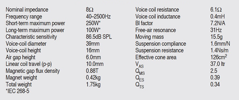
At the same time the rear of the basket is designed to be as open as possible, using thin but strong “arms” that minimize early reflections at the rear of the cone. The area behind the spider is completely open as well, eliminating air compression and “chuffing noise.” Complete specifications for the Excel woofer are listed in Table 1.
Which TL Geometry?
After describing the performance of straight TLs in the first two parts of his series for Speaker Builder, Augspurger details five alternate geometries in Part 34 that provide certain benefits over a straight pipe. Of these, two will be used in the THOR system, and the benefits of a third will be obtained by alternate means. The particular geometries are the tapered line, the offset driver line, and the coupling chamber line. The benefits of each are as follows.
1. Tapering the line broadens its fundamental resonance and thereby increases the frequency range of constructive pipe output. The f3 value is typically 0.8 times fp. Attenuation of upper harmonics is comparable to a straight line. Augspurger recommends tapers in the range of 3:1 to 4:1.
2. Offsetting the driver from the closed end of the line by one-fifth its length reduces the first passband dip, thus smoothing low-frequency response. However, f3 must be set about 20% higher than fp for the flattest response.
3. A coupling chamber between the driver and the pipe inlet lowers the fundamental frequency of the combination. The coupling chamber compliance combines with the resistive acoustic impedance of the damped line to produce a first-order low-pass filter that increases high-frequency attenuation.
It was clear to me at the outset that I wanted to use a tapered line to get a low f3 with fairly broad low-frequency reinforcement. Additionally, with the MTM driver configuration one driver is automatically offset from the closed end of the line. This driver offset will mitigate somewhat against the low-frequency extension provided by the taper, but will help to reduce midbass response ripple.
Finally, folding the line provides additional high-frequency attenuation, somewhat like that obtained with the chambered line. With these considerations in mind, I describe the initial layout and sizing of the THOR TL.
Sizing THOR
A big advantage of sealed and vented box design is that Thiele and Small, among others, have established strict relationships between driver parameters and box volume and, in the case of vented designs, box tuning, for a specified frequency response. This greatly simplifies the design process for these systems.
The significance of Augspurger’s work is that for the first time we now have relationships between the driver parameters fS, QTS, VAS, and the TL frequency, fP, and volume, VP. Strictly speaking, his relationships are not unique, but they do represent an excellent starting point and give us confidence that a good design can be attained.
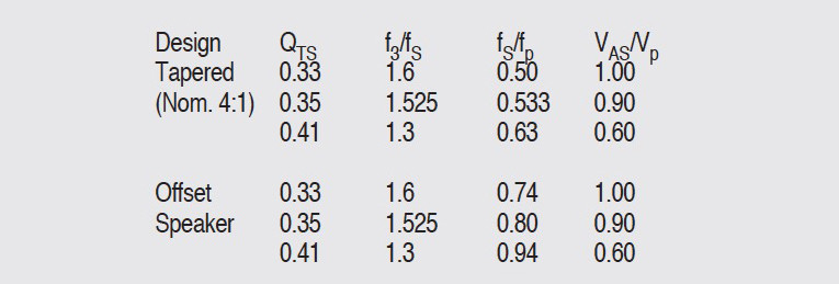
The starting point for TL sizing is Augspurger’s table of extended system alignments given in Part 3 of his series. Portions of that table are reproduced here in Table 3. These alignments are optimum in the sense that they approximate the response of an equal volume closed box, but with reduced cone excursion when the damping is adjusted for a ±1dB passband ripple. Fortunately, the TL is a non-resonant system so that the optima are broad. As you will shortly see, significant departure from the alignments Augspurger recommends can be made with little loss of performance.
The driver parameters needed to enter Table 3 are fS, QTS, and VAS. Values of those parameters for the Excel W18E001 woofer are given in Table 1. The line QTS = 0.35 (which includes the effect of the crossover coil resistance on driver Q) in Table 3 has been interpolated from the QTS values of 0.33 and 0.41 given in Augspurger’s Table 2 of reference [4]. Notice that the columns headed f3/fS and VAS/Vp are the same for both the tapered and offset speaker configurations for the same QTS. Thus f3 and Vp will be the same for both, but the line lengths will differ.
From Table 3, the predicted f3 is:
f3 = 1.525fS = 1.525 × 31Hz = 47.3Hz
For the tapered line, fp is calculated to be:

The line length, Lp, is then one quarter of a wavelength at fpT.

In this equation, c, the speed of sound in air, is taken to be 13584 in/sec. A similar calculation for the offset line gives a line frequency of 39.2Hz and a line length of 86.6″. The total line length actually used is 81″. With this length an f3 of 44Hz is achieved. Column 4 of Table 3 tells how to compute the TL internal volume as a function of VAS. From Table 3 you find that:

Now VAS for the MTM configuration is twice the VAS of a single driver or 74L. Solving for Vp you get:

You must establish at least two dimensions of the enclosure before you can use the volume calculation to get the final dimension. Here some practical considerations entered. I knew I wanted a tweeter height of 34–35″ to match ear height at my favorite listening position. I also knew from earlier experience with woofers of this size that a front baffle width should be no greater than 9″ for uniform horizontal polar response. Finally, I wanted to isolate the crossover from the main acoustic volume by placing it in the base of the enclosure.
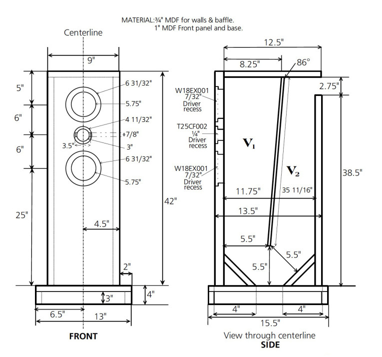
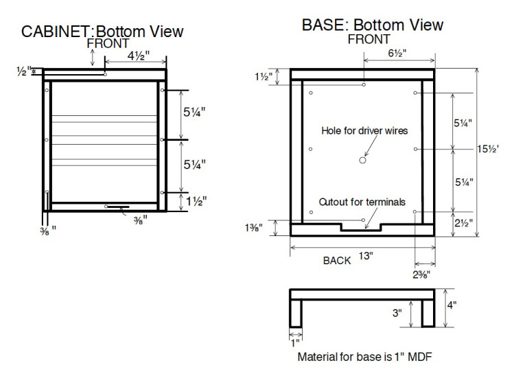
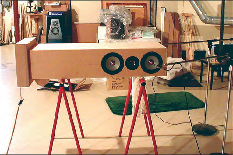
These considerations led to a trial layout for the front baffle of the THOR TL shown in Fig. 1A. Now all that was needed was to determine the interior and exterior depths of the line. A first cut at line depth went like this. Assuming 0.75″ MDF for the sides and top leads to an internal width and height of 7.5″ and 41.25″, respectively. The internal depth, d, is then computed as follows:

To get the external depth you must add the thickness of a 1″ front baffle, a 0.75″ internal baffle, and a 0.75″ rear panel for an overall depth of 18.75″. This number was considerably deeper than I wanted and would lead to a rather large and heavy enclosure.
At this point I made a number of arbitrary decisions. I chose a line taper of 3:1 and limited the overall depth to 13.5″. This led to the internal layout of the line shown in Fig. 1A. Placing the interior baffle at an angle produces the desired taper. A side, but important, benefit of the interior baffle is that it adds greatly to enclosure rigidity, effectively clamping the side panels together and largely eliminating side-wall vibration.
The resulting layout has a throat area of 61.875 in2, which is roughly 1.6 times the combined diaphragm area of the two drivers, and an exit area of 20.625 in2. As you will see, this departure from Augspurger’s recommendation has little effect on f3.
Filling The Line
In Table 1, Part 3, of the Augspurger article (4), the author recommends packing densities for four filling materials. The optimum packing density is a function of line length. For my first trials I used polyester fiber (“Poly-Cat” polyfill available at Wal-Mart). For a line length of 81″ the recommended packing density is 0.78 lbs/ft3. To get the total amount of polyester needed you must calculate the TL internal volume. From Fig. 1A the internal volume is calculated to be 1.934ft3, and the total amount of polyfill needed is then 1.934 × 0.78 = 1.61 lbs = 24.1 oz.
In the past, some authors have suggested varying the packing density along the line length, but Augspurger found no particular advantage to this in his studies and recommended a uniform density. Getting a uniform packing density is a bit tricky, however, because the line volume per unit length is changing due to the taper.
Referring again to Fig. 1A, the volumes of the two line sections, V1 and V2, are found to be 1.208ft3 and 0.725ft3, respectively. These volumes represent 62.5% and 37.5% of the total line volume, respectively. Now to get a uniform packing density, you should place approximately 15 oz of the polyfill in V1 and 9 oz in V2.
The Approach To Line Trimming
Once TL dimensions are set, final trimming of the TL packing density is done using a sequence of electrical impedance and acoustic measurements. I could jump to the final result, but I think the various steps in the process are instructive because they can be used in general to trim any transmission line. I will also take this opportunity to compare results from the tapered line with an equivalent straight line driven with a single woofer.
The acoustic measurements are similar to those used by Augspurger in his article. Near-field woofer and port SPL measurements are taken using the Audiomatica CLIO measurement system in the MLS mode. The near-field technique is used to overcome the effects of low-frequency standing waves.
In this technique, the microphone is placed very close to the driver diaphragm (<0.1″) to swamp out diffraction and room effects. At low frequencies where the diaphragm acts like a rigid piston, the measured near-field response is directly proportional to the far-field response and independent of the environment into which the driver radiates. Based on the diameter of the W18 woofers, the near-field woofer measurements are valid up to about 860Hz.
CLIO works in the time domain and produces both amplitude and phase response data. The woofer and port responses are measured separately and then added, taking proper account of phase and woofer/port area differences to get the complete low-frequency response of the line. This process is described in detail in Chapters 4 and 7 of my book, Testing Loudspeakers (5). Photo 1 shows the lab setup for testing and trimming the line.
When measuring the port near-field response, you must place the microphone in the plane of the port exit. The port measurement is then corrected by multiplying it by the square root of the ratio of port area to the combined area of the two woofers. This correction is:

After correction, the port response is added to the two woofer responses to get the complete near-field TL response.
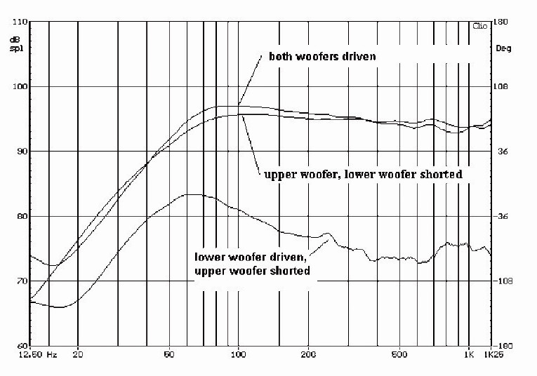
There is a potential problem with near-field measurements of woofer response with the MTM configuration. If both woofers are driven simultaneously, the near-field response of one woofer can be contaminated by the output from the second woofer because they are so close together. This is illustrated in Fig. 2.
The results shown in Fig. 2 are for an MTM speaker using two 5.25″ woofers in a sealed enclosure, but the results will apply equally well to THOR. In this series of tests, the microphone is placed about 0.1″ in front of the upper woofer dust cap.
Figure 2 has three plots. One plot is the near-field data taken at the upper woofer with the lower woofer terminals shorted. A second plot shows the acoustic response measured at the upper woofer with the lower woofer driven and the upper woofer shorted. Below 60Hz, the lower woofer signal is only 10dB below the upper woofer output.
The third curve shows the response at the upper woofer with both woofers driven. You see that this plot is contaminated with some of the output from the lower woofer. In practice, the near-field response of each woofer is measured separately with the other woofer shorted, and then both responses are added to get the total low-frequency response of the woofer pair.
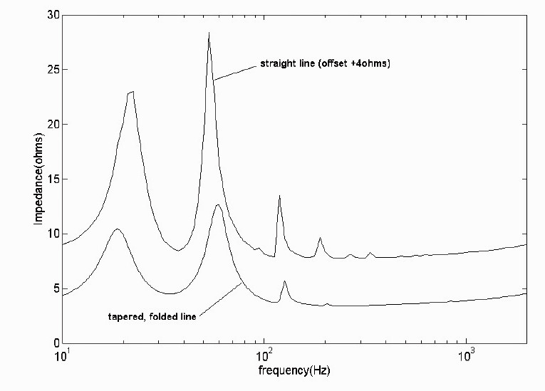
So far I’ve spoken only about acoustic measurements, but you can also tell a great deal about TL performance from impedance data. Figure 3 compares the measured woofer impedance of the tapered, folded line with an equivalent straight line. Both lines are unfilled. The straight-line plot is offset by +4Ω to ease the comparison.
First notice that both lines exhibit the double-peaked curve of a vented loudspeaker. Thus, up to first order, the unfilled line acts much like a bass reflex speaker. However, you also see additional impedance peaks due to higher-order modes of the line. Beyond the first two peaks, the straight-line TL shows four additional peaks with increasing frequency.
Contrast this with the tapered, folded line where: 1) the minimum between the two lower peaks occurs at a lower frequency, 2) the curve about the minimum is broader and shallower, 3) all peaks are more highly damped relative to the straight line, and 4) only a total of three peaks are seen in the folded, tapered line versus six for the straight line.
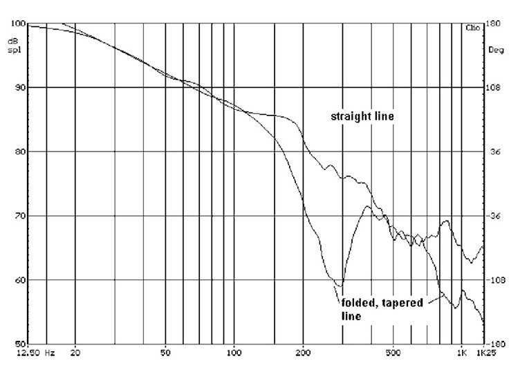
These results support the contention that a tapered line has a lower fundamental resonant frequency and a broader range of support. The absence of higher-frequency peaks is due to folding the line. You will see this more clearly later on when you compare transfer functions for optimally damped straight and tapered lines in Fig. 8.
Trimming The Line
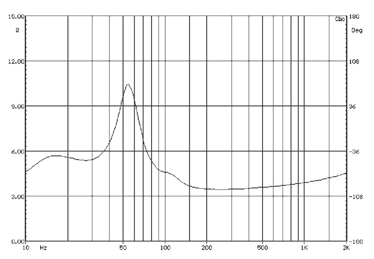
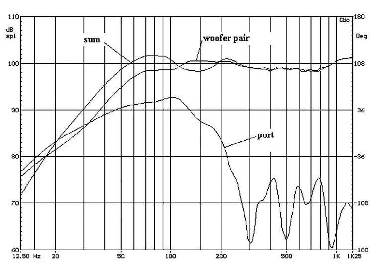
Rather than going directly to the “optimum” calculated packing density, I first packed the line uniformly to half the recommended density; i.e., 13 oz of polyfill. The impedance plot for this condition is shown in Fig. 4. Notice that the first impedance peak just below 20Hz is almost gone. The same is true for the third peak just above 100Hz. The impedance curve looks almost like that of a closed box speaker.
Responses of the woofer pair, the port, and their sum are shown in Fig. 5. The summed response shows a peak-to-peak ripple below 500Hz of ±1.7dB. The low-frequency f3 point relative to 500Hz is 41Hz. Below 41Hz response falls off at 12dB/octave.
Finally, observe that the port output augments woofer output by 4–5dB at all frequencies between 20Hz and 110Hz. From these results you can conclude that the lightly damped TL acts like an underdamped closed box system with 4–5dB increased low-frequency output capability.
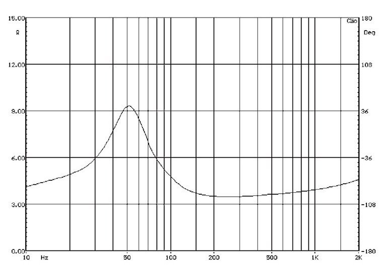
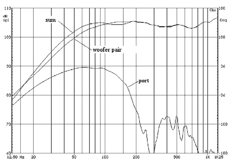
The impedance curve of the optimally filled TL (24 oz) is shown in Fig. 6. Now all traces of line modes are gone and the curve is almost purely second order like that of a closed box. The line is now essentially non-resonant. Responses of the woofer pair, the port, and their sum are shown in Fig. 7. The summed response ripple is ±0.6dB and f3 is 44Hz. Bass augmentation averages 3–4dB from 20Hz to 100Hz.
From these results you can conclude that for a fixed line length there is a trade-off between ripple response and f3 controlled by line damping. You also see that the line can be damped effectively by observing only the impedance curve. Damping should be adjusted until all traces of line modes just disappear from the impedance curve.
From the impedance plot you can compute an equivalent QTC for a second-order system with the same impedance curve using any of the procedures outlined in Chapter 2 of reference [5]. The value obtained is QTC = 0.55, indicating that the woofer pair is almost critically damped.
The woofer/port transfer function plot shows the acoustic output at the TL port produced by the acoustic input to the line coming off the rear of the woofer cones. If you compare the woofer/port transfer function for an optimally damped straight line against an optimally damped tapered and folded line, you get the plot shown in Fig. 8. Between 100 and 400Hz and again above 700Hz there is much less high-frequency acoustic output from the port of the folded, tapered line. This greatly reduces ripple in the 100 to 400Hz range relative to that of a straight line.
Continues on Page 2 >>>


