Founding partners for Neotera include Erik Thorsell, Greg Turnidge, and Maurizio Servadio. Thorsell invented and patented the popular “Fresh Air” car subwoofer system and is based in Sweden. Turnidge is the Managing Director of Neotera and Blue Acoustics (Blueacs) and is based in Australia. Servadio is the engineer who invented the Neotera Ultraflat technology and is based in Italy where the UF295FAS is manufactured. Interestingly, both Thorsell and Turnidge worked with Neville Thiele for years up to his passing, which is impressive. In addition, industry veteran David Stephens is Director of Sales & Marketing for Neotera.
Voice Coil has explicated several thin-profile woofers over the years, including drivers from Dayton Audio, Prescient Audio, SB Acoustics, and Wavecor. Virtually all of these previously featured woofers were subwoofers with the thin-profile aspect meant to complement shallow depth mounting situations. While it is a thin-profile woofer with a depth of 2.6” with a low-frequency response down to 29Hz, unlike the other thin-profile woofers, the Neotera has a upper frequency response that allows it to be crossed over as high as 1kHz. However, what really distinguishes the UF295FAS is that it is specifically designed for dipole system applications in the vein of a speaker, such as Sigfried Linkwitz’s LX521 constant directivity dipole speaker.
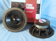
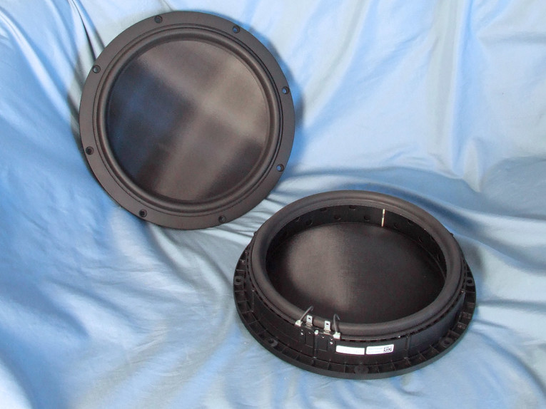
Features for the UF295FAS are seriously impressive. As shown in Photo 1, the fiberglass/Rohacell sandwich single piece (no dustcap) cone is suspended by two EPDM (ethylidene norbornene [ENB], dicyclopentadiene [DCPD], and vinyl norbornene [VNB] — 4% to 8% of these monomers are typically used) — rubber surrounds.
Both surrounds are narrow (11mm front and 13mm rear) and about as tall as they are wide. The cone is driven at its perimeter by a 283.4mm voice coil wound with aluminum wire with a black emissive coating on an aluminum former, also with a black emissive coating.
This is somewhat similar to the Prescient Audio TD-12 subwoofer (characterized in Voice Coil, August 2015) in that the cone was also driven at its perimeter. This also makes the UF295FAS’s 283.4mm diameter voice coil one of the largest diameter voice coils in the loudspeaker industry.
The motor structure is also unique in that it uses a series of 72 28mm-high neodymium bar magnets for a total magnet mass of 1.4 kg. The 28mm-high neo magnets directly drive the 7mm-high voice coil for a 10.5mm Xmax.
Interestingly, and undoubtedly the only solution, the entire 72 magnet motor is charged after assembly and is completed using a massive 52 kilojoules (kJ) magnetizer! Incidentally, the drivers are produced on a semi-automatic production line in an Italian loudspeaker factory. Remaining features include a 250W AES-rated power handling, a frame made of Zamak 5 zinc alloy, and mechanical excursion of ±20mm.
The 30V curves were too nonlinear to get a sufficient curve fit, and were discarded. The remaining 12 stepped sine wave sweeps for each woofer were further processed with the voltage curves divided by the current curves to produce impedance curves. Phase curves were generated using the LEAP phase calculation routine, after which the impedance magnitude and phase curves plus the associated voltage curves were then copy/pasted into the LEAP 5 Enclosure Shop software’s Guide Curve library. This data was then used to calculate parameters using the LEAP 5 LTD transducer model.
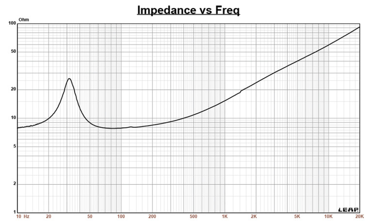
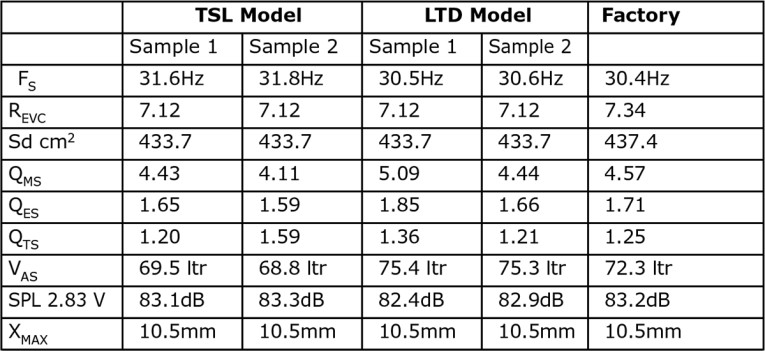
Because most manufacturing data is being produced using either a standard transducer model or in many cases the LEAP 4 TSL model, I also generated LEAP 4 TSL model parameters using the 1V free air that can also be compared with the manufacturers data. Figure 1 shows the UF295FAS’s 1V free-air impedance plot. Table 1 compares the LEAP 5 LTD and LEAP 4 TSL Thiele-Small (T-S) parameter sets for the Neotera UF295FAS dipole thin-profile woofer samples along with the Neotera factory data.
From the comparative data shown in Table 1 for the UF295FAS 8Ω dipole woofer, you can see that all four parameter sets for the two samples were very similar and correlated rather well with the factory data.
Following my normal protocol for Test Bench testing, I used the sample 1 LEAP 5 LTD parameters and set up a computer box simulation. Fortunately, the LEAP 5 Enclosure Shop has a dipole simulation model. Given this, I set up a dipole simulation with the driver centered on a 24” wide, 38” tall, and 0.75” thick baffle placed in full-space (4π). Note that virtually all the enclosure simulations in Test Bench are done in half-space (2π) to make reading the -3dB frequency easier to do.
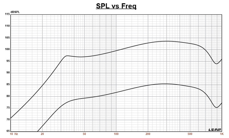
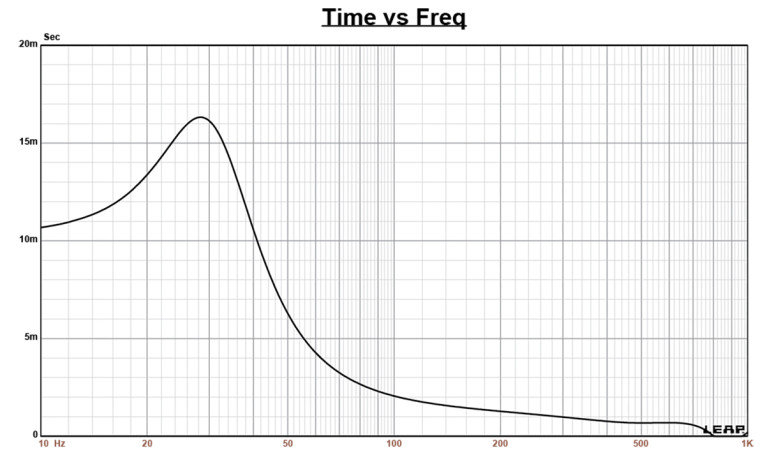
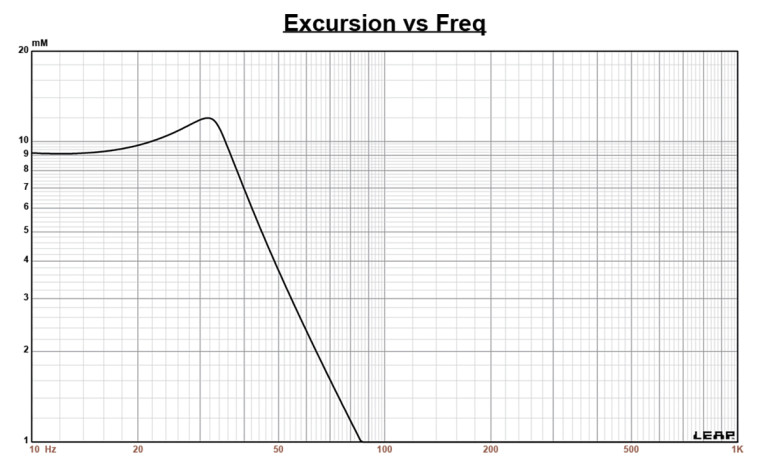
Figure 2 gives the 4π dipole flat panel simulation results at 2.83V and at a voltage level sufficiently high enough to increase cone excursion to Xmax+15% (12mm for UF295FAS). This resulted in an F3 of 29Hz (-6dB=25Hz) with a Qtc=1.2 (the Qts of the driver in free air plus the minor effect of the baffle). Increasing the voltage input until the approximate Xmax+15% maximum linear cone excursion point was reached resulted in 97.5dB at 25.5V for the 4π dipole simulation. Figure 3 shows the 2.83V group delay curve and Figure 4 shows the 25.5V excursion curve.
This month the Klippel analysis for the Neotera Ultraflat UF295FAS dipole woofer was performed by Neotera engineers on a Klippel DA2 analyzer, which produced the Klippel data graphs given in Figures 5-8. Note that I normally have Klippel analysis done by either Redrock Acoustics or Warkwyn, however, due to time restraints this month, I decided to use the Neotera data, which given the caliber of the parties involved, was more than appropriate.
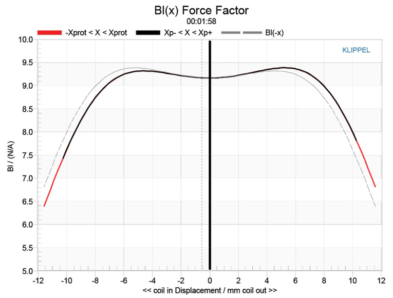
The Bl(X) curve (Figure 5) is moderately broad and very symmetrical, and with a small amount of offset. Looking at the Bl symmetry curve (Figure 6) shows a negligible 0.66mm Bl coil-out (forward) offset once you reach an area of reasonable certainty around 6mm, decreasing to a trivial 0.01mm at the physical 10.5mm Xmax, so relatively minor.
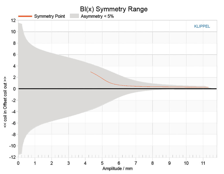
Figure 7 and Figure 8 show the Kms(X) and Kms symmetry curves for the Neotera dipole woofer. Like the Bl curve, the Kms stiffness of compliance curve shown in Figure 7 is very symmetrical, with practically no offset. The Kms symmetry range curve depicted in Figure 8 likewise indicates a negligible 0.16mm coil-out (forward) offset once you reach an area of reasonable certainty around 4mm, decreasing to not significant 0.09mm at the physical 10.5mm Xmax.
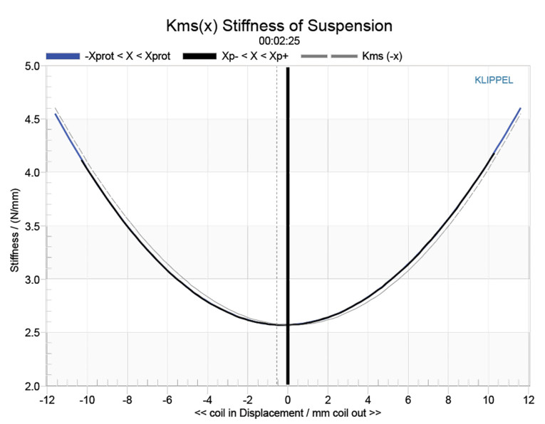
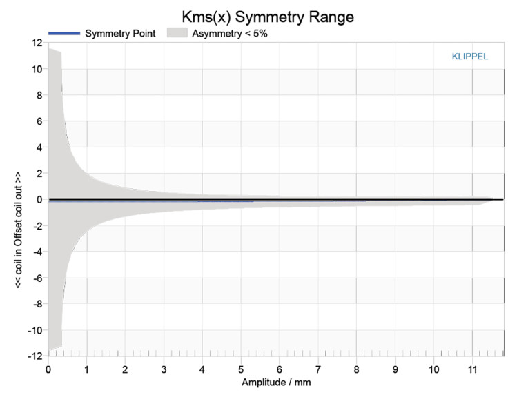
Figure 9 gives the inductance curve Le(X) for the Neotera dipolar transducer. Motor inductance will typically increase in the rear direction from the zero-rest position as the voice coil covers more of pole, however does not use a pole piece motor structure. What we do get is lower inductance variation from full in to full out travel, which is the goal you want to achieve. The UF295FAS inductance only varied about 0.046mH from Xmax in to Xmax out, which is very minimal inductance change and indicates excellent inductive performance, obviously an affectation of this type of motor structure.
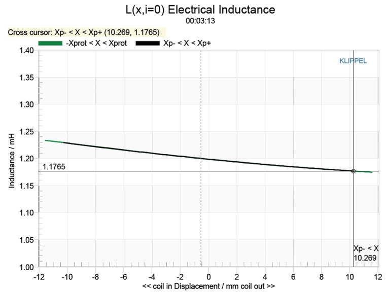
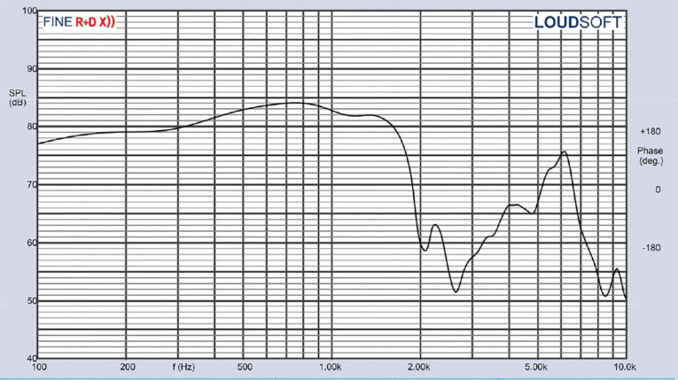
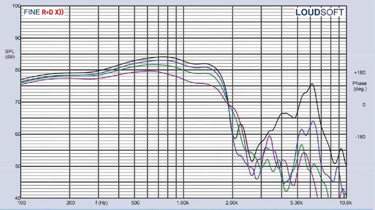
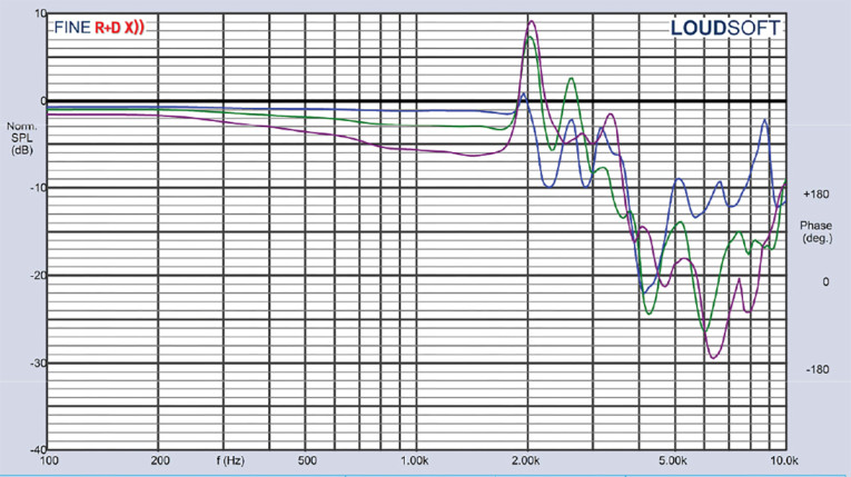
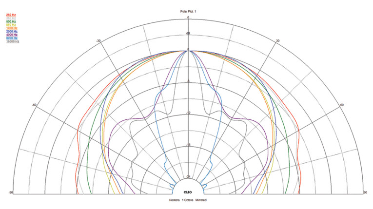
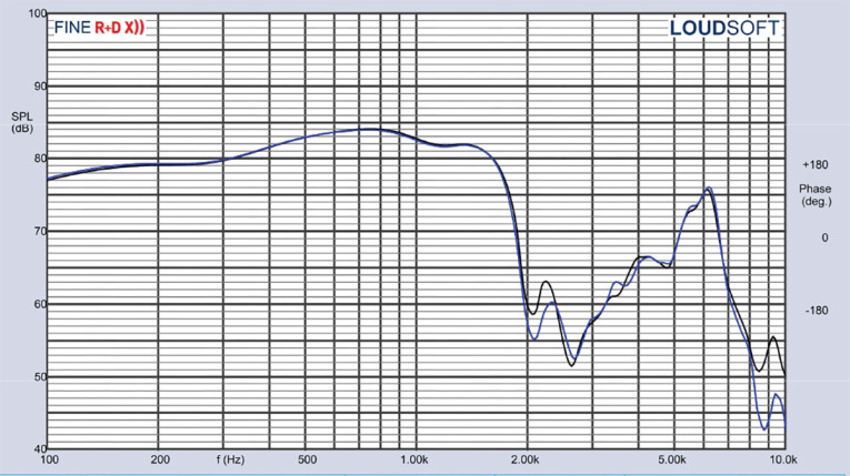
Figure 10 gives the UF295FAS’s on-axis response, indicating a smooth rising response from 200Hz to 1.5kHz. Figure 11 displays the on- and off-axis frequency response at 0°, 15°, 30°, and 45°, showing the typical directivity for a 10” woofer. A -3dB at 30° with respect to the on-axis curve occurs at about 1kHz to 1.2kHz, so is a reasonable upper frequency for a low-pass crossover for a two-way design. However, this woofer would be more appropriately utilized in a three-way design, with a crossover to a dipole midrange at 300Hz to 500Hz. The normalized version of Figure 11 is given in Figure 12. And Figure 13 shows the CLIO polar plot (in 10° increments and 1/3 octave smoothing).
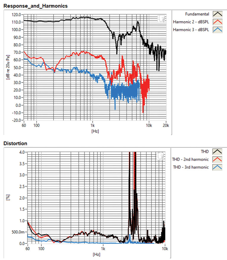
For the last remaining series of tests, I initialized the Listen SoundCheck AudioConnect analyzer and SCM ¼” microphone to measure distortion and generate time-frequency plots (both devices provided courtesy of Listen, Inc.). For the distortion measurement, I rigidly mounted the Neotera thin-profile driver in free air and set the SPL to 94dB at 1m (15.4V), using a pink noise stimulus. I then measured the distortion with the Listen microphone placed 10cm from the driver. This produced the distortion curves shown in Figure 15, with the third harmonic distortion staying primarily between under 0.1% to 0.3% from 100Hz to 1kHz.
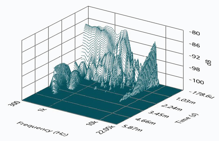
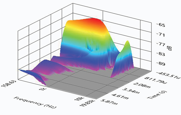
For the final time domain plots, I set up SoundCheck to get a 2.83V/1m impulse response for this driver and imported the data into Listen’s SoundMap Time/Frequency software. Figure 16 shows the resulting cumulative spectral decay (CSD) waterfall plot. Figure 17 shows the Wigner-Ville plot (chosen for its better low-frequency performance).
The Neotera UF295FAS is virtually the only dedicated dipole application woofer to grace the pages of Voice Coil’s Test Bench. This is unique and well-thoughtout transducer, as borne out by the above analysis. For more information, visit www.neoteraaudio.com, or contact David Stephens directly by email here. VC
This article was originally published in Voice Coil, November 2023.