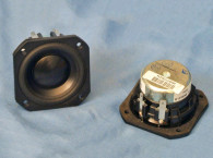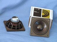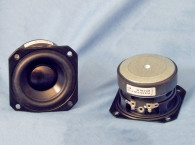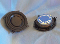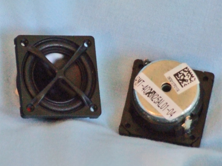
The Peerless by Tymphany PMT-40N25AL01-04 is a 25-mm (1”) diameter full-range driver built on a proprietary injection-molded two-piece polycarbonate (one piece for the motor assembly structure and one piece for the protective grill). The cone assembly consists of one piece of inverted aluminum suspended with a foam surround that provides all the compliance (there is no spider mechanism). As with all the 1” long-throw inverted dome drivers on the market, it has a 26-mm diameter voice coil. This is wound with round copper wire on a polyimide (Kapton) former, terminated to opposite mounted solderable terminals.
It also has magnetic fluid in the gap. Since it was not mentioned in the literature, I assume this is a low-viscosity fluid that does not impact the compliance. A neodymium motor using a neodymium slug and a milled return cup drives the cone assembly. For cooling, the return cup, the neodymium slug, and a metal top plate separated from the slug by an insulated layer have a 5-mm diameter hole that forms a pole vent.
I used the LinearX LMS analyzer and VIBox to create voltage and admittance (current) curves with the PMT-40N25AL01-04 clamped to a rigid test fixture in free air at 0.3, 1, 3, and 6 V. I discarded the 6-V curves as being too nonlinear for LEAP 5 to get a good curve fit. The current Test Bench testing protocol no longer uses a single added mass measurement. Instead, I use the actual physically measured Mmd supplied by the manufacturer. Some manufacturers just add up all the parts weight from a bill of materials (BOM) and include something for the adhesive weight. Next, I post-processed the PMT-40N25AL01-04 sample’s six 550-point stepped sine wave sweeps and divided the voltage curves by the current curves (admittance) to produce the impedance curves, which are phase-generated by the LMS calculation method.
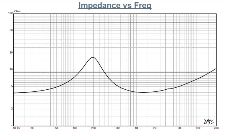
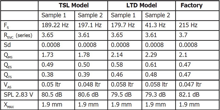
I imported them along with the accompanying voltage curves to the LEAP 5 Enclosure Shop software. Since most Thiele-Small (T-S) data provided by OEM manufacturers is produced using a standard method or the LEAP 4 TSL model, I additionally used the 1-V free-air curves to create a LEAP 4 TSL model. I selected the complete data set, the LTD model’s multiple voltage impedance curves, and the TSL model’s 1-V impedance curve in the transducer derivation menu in LEAP 5. Then, I created the parameters for the computer box simulations. Figure 1 shows the 1-V free-air impedance curve. Table 1 compares the LEAP 5 LTD, TSL data, and factory parameters for both PMT-40N25AL01-04 samples.
The PMT-40N25AL01-04’s LEAP LTD multi-voltage parameter calculation results were close to the factory data, while the QTS for the TSL parameters exhibited a somewhat lower number. However, I followed my usual routine and used the LEAP LTD parameters to set up computer enclosure simulations for Sample 1. I also programmed two computer enclosure simulations into LEAP. The first simulation used a 2.1 in3 sealed-box alignment (with 50% damping material in the box). The second simulation was more involved. A vent is possible, but to keep it short enough to fit into a small enclosure, it becomes less than 0.25” in diameter. A passive radiator would work well in this circumstance and is typical of numerous current market offerings using this type of driver. However, another alternative is to use the capacitor boost system described in Neville Thiele’s article, “Closed-Box Loudspeaker with a Series Capacitor,” which originally appeared in the Journal of the Audio Engineering Society (JAES) and was reprinted in Voice Coil, November 2012.
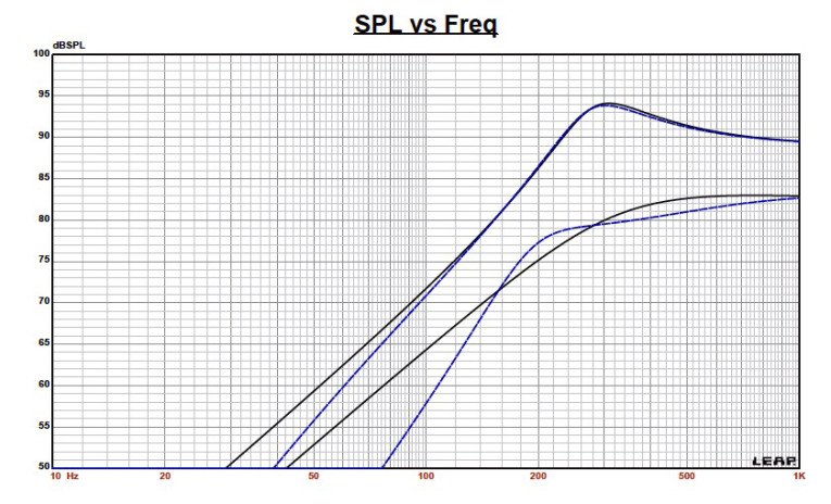
I have used this technique in production on several occasions and it is an effective low-cost method to get more bass out of a driver, especially small-diameter drivers. For the PMT-40N25AL01-04, I used the same size sealed box, a 2.1 in3 in conjunction with a 150-μF series capacitor. Figure 2 displays the PMT-40N25AL01-04’s results in the two box simulations at 2.83 V and at a voltage level sufficiently high enough to increase the cone excursion to 2.2 mm (XMAX + 15%). This produced a F3 frequency of 299 Hz (F6 = 227 Hz), a 0.7 box/driver QTC for the 2.1 in3 unassisted sealed enclosure and –3 dB = 296 Hz (F6 = 189 Hz) for the 2.1 in3 assisted (cap boost) sealed-box simulation.
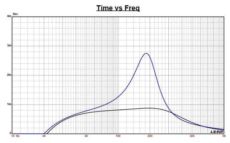
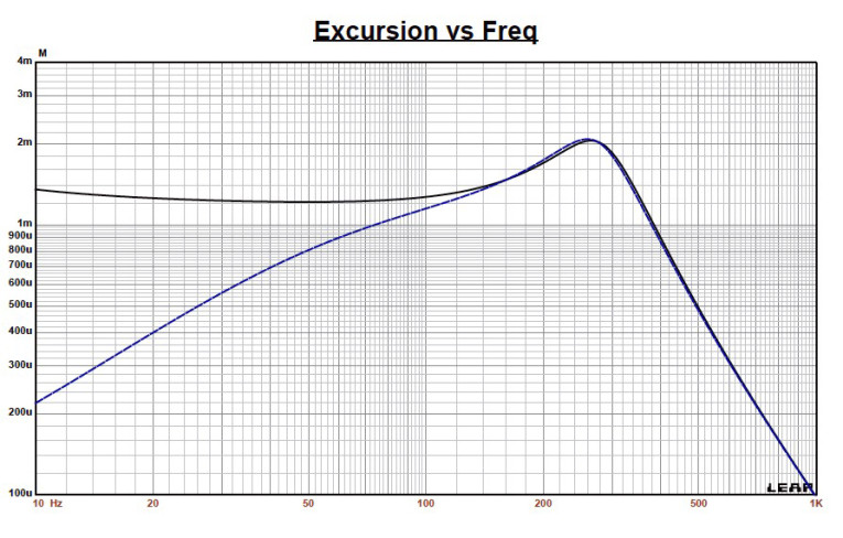
I increased the voltage input to the simulations until the maximum linear cone excursion resulted in 95 dB at 25 V for the sealed enclosure simulation and 94 dB with the same 25-V input level for the assisted sealed box. Figure 3 and Figure 4 show the 2.83-V group delay curves and the 25-V excursion curves. Note that 25 V may exceed this driver’s thermal limits. Klippel data for this driver was not included this month due to space limitations.
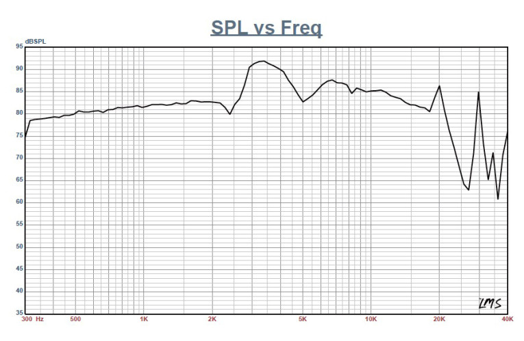
Next, I mounted the PMT-40N25AL01-04 in an enclosure with a 4" × 9” baffle and filled with damping material (foam). I used the LinearX LMS analyzer set to a 100-point gated sine wave sweep to measure the transducer on and off axis from 300-Hz-to-40-kHz frequency response at 2.83 V/1 m. Figure 5 shows the PMT-40N25AL01-04’s on-axis response, indicating a smoothly rising response to about 2.2 kHz followed by a broad 10-dB peak between 2.3 and 5 kHz. This response is typical of this type of low-resonance inverted aluminum dome 1" driver. Above 5 kHz, the response extends to 20 kHz.
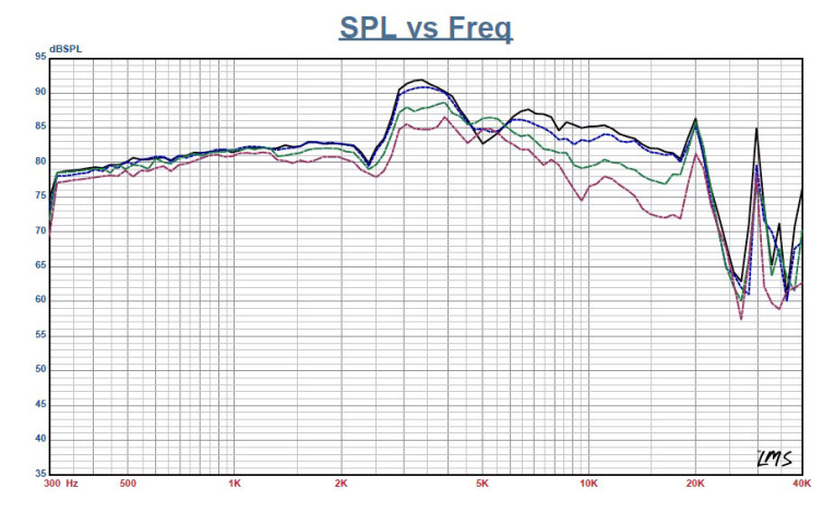
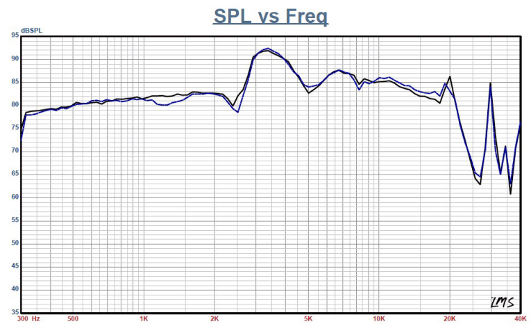
Figure 6 shows the on- and off-axis frequency response at 0°, 15°, 30°, and 45°. The rolloff at 30° off axis is almost as good as a 1" dome so I would expect this driver’s full-range fidelity to be reasonably good. Figure 7 shows the final sound pressure level (SPL) measurement. The two-sample SPL comparison for the PMT-40N25AL01-04 shows a close match to within less than 1 dB throughout the operating range, with some larger variations between 1 and 1.5 kHz.
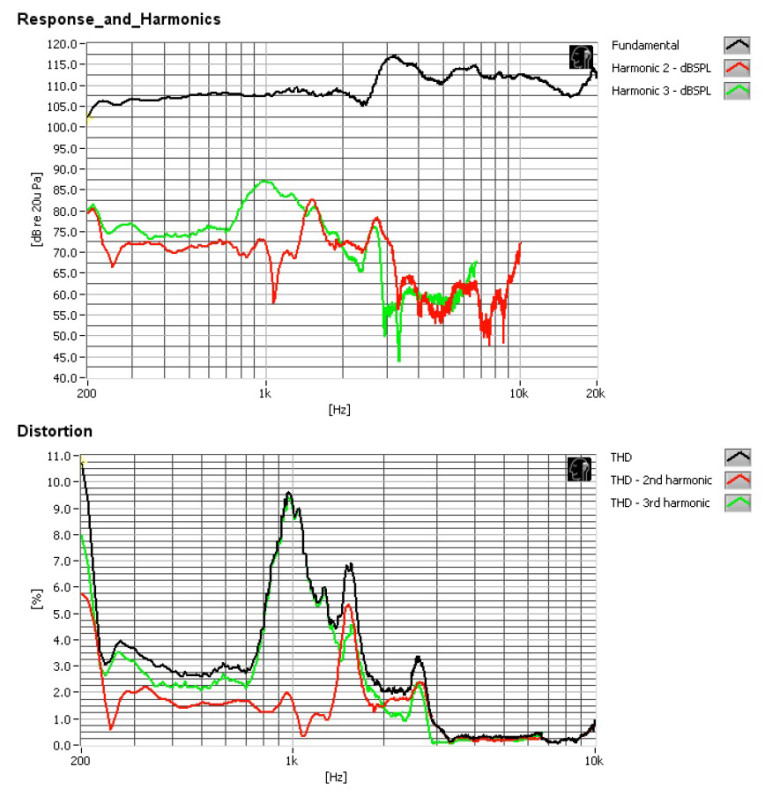
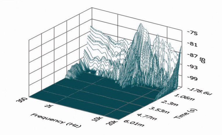
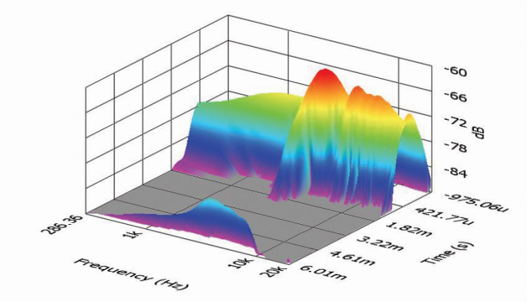
Next, I used the Listen SoundCheck AmpConnect analyzer and the SoundCheck V. 12 software along with the Listen 0.25" SCM microphone and power supply (courtesy of Listen) to measure distortion and generate time-frequency PMT-40N25AL01-04 in free air, and used a noise stimulus to set the SPL to 94 dB at 1 m (8.1 V). I measured the distortion with the microphone placed 10 cm from the dust cap. Figure 8 shows the distortion curves. I used SoundCheck to get a 2.83-V/1-m impulse response and imported the data into Listen’s SoundMap time-frequency software. Figure 9 shows the resulting cumulative spectral decay (CSD) waterfall plot. Figure 10 shows the Wigner-Ville plot, which I used for its better low-frequency performance. While the intended application for this PMT-40N25AL01-04 is for multimedia lifestyle speakers and thin-format LCD TVs, this transducer format has been a favorite for line-source applications. For more information, visit www.tymphany.com.
This article was originally published in Voice Coil, July 2014.