Together this talented trio fielded more than 40 transducer patents, which is to say the least, impressive. While the partnership is no longer intact, Stiles is still developing MMAG woofers, one of the latest examples being the Dayton Audio Epique E180HE-44. Stiles is an independent transducer engineering consultant and developed the two new Epique full-range subwoofers in conjunction with the engineering team at Dayton Audio. If you are interested in acquiring his transducer engineering services, he can be reached at this email.
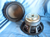
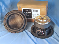
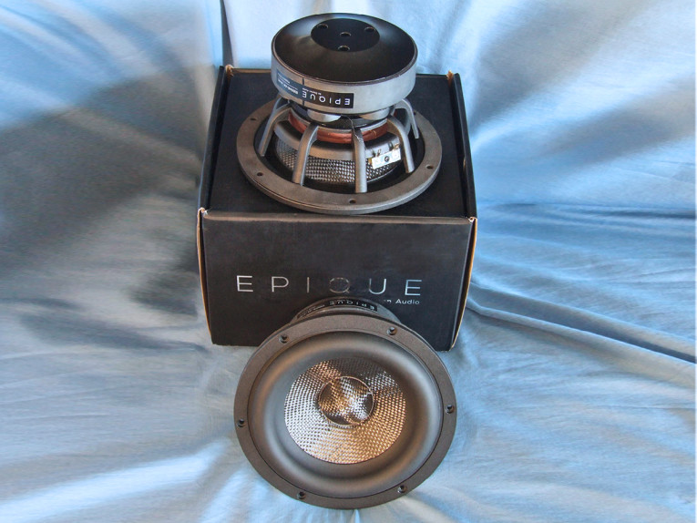
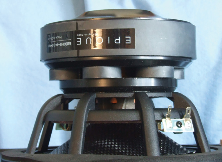
The Dayton Epique E180HE-44, as with the E150HE-44 featured in the December 2021 issue of Voice Coil, is promoted as a full-range subwoofer. While a full-range subwoofer may sound like an oxymoron, it is actually an interesting concept, and one that is ideally suited to the MMAG technology given the typical high-excursion/low inductance aspect of this motor design. The E180HE, which as you would suspect is a scaled up version of the E150HE, and has a similar feature set that begins with a proprietary eight-spoke cast-aluminum frame, comprised of narrow (about 9.6mm) spokes, completely open below the spider (damper) mounting shelf for cooling (Photo 1 and Photo 2). Additional cooling for this driver is provided by six 4mm diameter vents in the voice coil former, as well as four 8mm diameter vents in the back plate. Additional cooling occurs as a result of the MMAG multi-magnet configuration.
The primary magnetic drive is provided by the 123mm × 25mm ferrite rear ring magnet, directly providing flux to the second rear 7mm gap. However, the secondary magnet system is comprised of six 28mm × 8mm ferrite disks. These magnets do not add flux to the upper 11mm gap, but rather act as magnetic “diodes” (aka gap balancing magnets) pulling the flux from the main magnet into the top 7mm gap. These disks also provide an 8mm space between the two 7mm gaps as well as a convention cooling path for the voice coil as it travels between the two gaps.
The cone assembly consists of an extremely stiff curvilinear shaped carbon fiber cone fitted with a 1.75” diameter carbon fiber dust cap. Compliance is provided by 21mm wide NBR surround that has a mostly shallow transition to the cone attachment, with the remaining compliance coming from a 4” diameter flat cloth spider (damper).
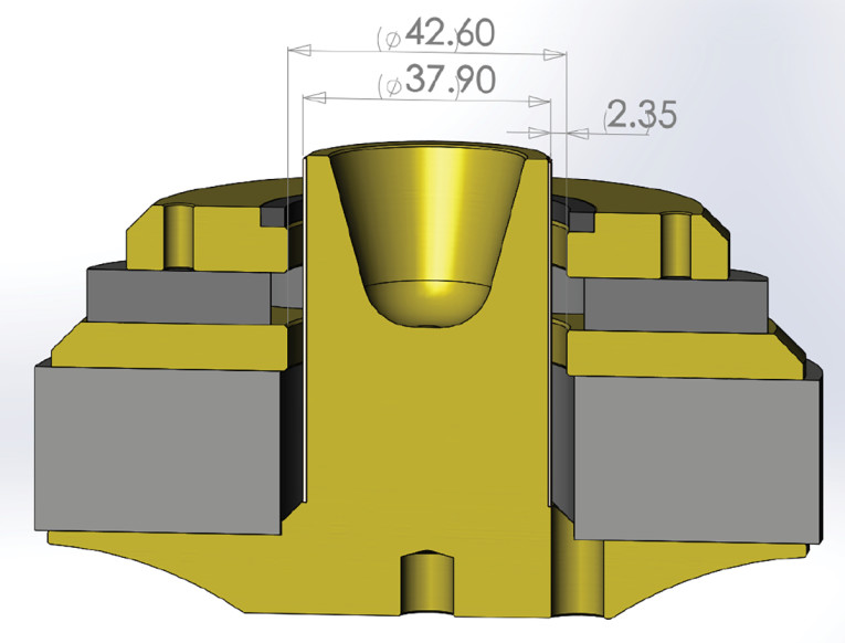
The motor is an FEA-optimized dual ferrite magnet type with milled plates and extended copper sleeve shorting ring (Faraday Shields) on the pole piece (see the motor cutaway drawing shown in Photo 3). Driving the cone assembly is a 38mm (1.5”) diameter dual voice coil (two 4Ω coils) wound with round copper-clad aluminum wire (CCAW) on aluminum former. Last, RMS power handling is rated at 200W and the voice coil tinsel lead wires are stitched into the spider. The leads are then terminated to gold-plated solderable terminals located on opposite sides of the former to discourage rocking modes.
I began testing the Dayton E180HE-44 full-range subwoofer using the LinearX LMS analyzer and the Physical LAB IMP Box (same type fixture as a LinearX VI Box) to create both voltage and admittance (current) curves with the driver clamped to a rigid test fixture in free-air at 0.3V, 1V, 3V, 6V, 10V, 15V, 20V, and 30V with oscillator on time between sweeps to simulate the actual thermal process over time. The 30V curves were too nonlinear to get a sufficient curve fit and were discarded.
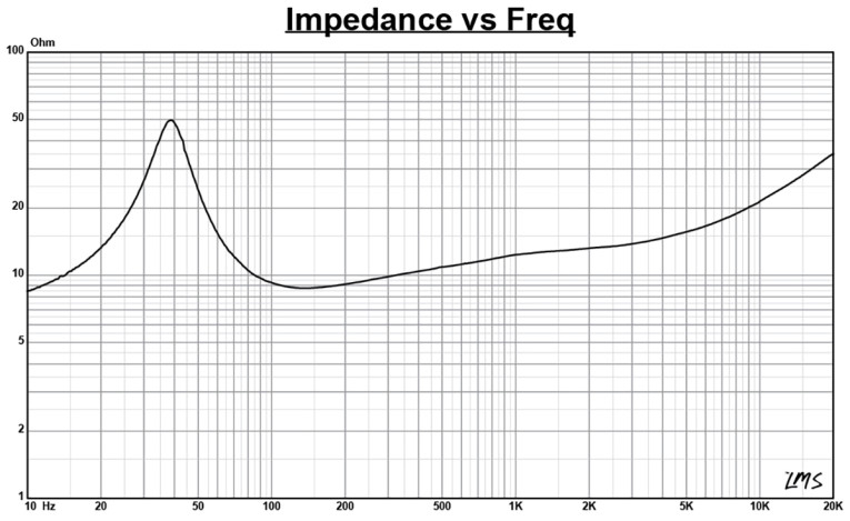
Following my established protocol for Test Bench testing, I no longer use a single added mass measurement and instead use the physically measured Mmd data (31.6 grams for the E180HE-44). The collected data, in this case the 14 550-point (0.3V to 20V) sine wave sweeps for each Epique sample were post-processed and the voltage curves divided by the current curves to generate impedance curves, with the phase derived using the LMS calculation method. I imported the data, along with the accompanying voltage curves, to the LEAP 5 Enclosure Shop software. Figure 1 shows the 1V free-air impedance curve. I selected the 1V TSL data in the transducer parameter derivation menu in LEAP 5 and created the parameters for the computer box simulations. Table 1 compares the LEAP 5 LTD/TSL TSP data and factory parameters for both of Dayton Audio E180HE-44 samples. Note that the E180HE voice coils were wired in series.
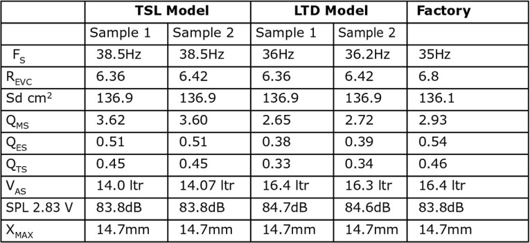
LEAP LTD and TSL parameter calculation results for the E180HE-44 subwoofer appear to correlate reasonably well with the factory published data. As normally I do in this column, I followed my established protocol and proceeded to set up computer enclosure simulations using the LEAP LTD parameters for Sample 1. If you ever wondered why I use the LTD parameter set over the TSL parameter set, it’s because the LTD model provides a more accurate maximum excursion estimation.
Two simulated enclosures were programmed into the LEAP 5 software, both specified by Dayton Audio. The first, a sealed box (Qtc or alignment not specified, only F3=62Hz) with 0.30ft3 air volume with 50% damping material (fiberglass), and a vented alignment with a 0.8ft3 volume with 15% damping material tuned to 30Hz. For the factory vented enclosure, alignment or tuning were not specified, only F3=30Hz.
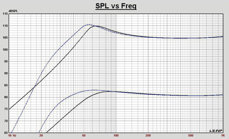
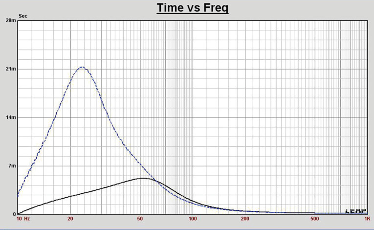
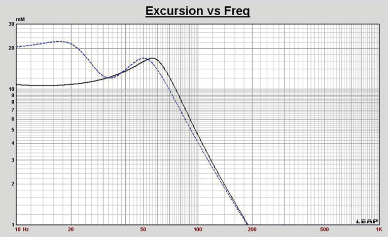
Figure 2 displays the box simulation results for the E180HE-44 full-range subwoofer in the sealed and vented enclosures at 2.83V and at a voltage level that achieves excursion equal to Xmax + 15% (16.9mm for the E180HE). This resulted in a F3 of 52Hz (-6dB=43Hz) with a Qtc=0.66 for the closed box, which was 10Hz lower than the Bass Box 6 (a less sophisticated enclosure program than LEAP 5) predicted. For the vented enclosure simulation, the result was -3dB=35Hz (-6dB=28Hz), which was 5Hz higher than the factory Bass Box prediction. Increasing the voltage input to the simulations until the Xmax +15% excursion was reached resulted in 110dB at 101V for the sealed enclosure simulation and 110.5dB with a 90V input level for the larger vented box. Figure 3 shows the 2.83V group delay curves. Figure 4 shows the 101V/90V excursion curves.
Klippel analysis for the 7” woofer was performed this month by Warkwyn’s Jason Cochrane with the Klippel KA3 analyzer. The Bl(X) curve for E180HE looks similar to what we saw in the E150HE, which was characterized in the December 2021 issue. Seen in Figure 5, the curve is moderately broad, but with an obvious degree of tilt. The Bl symmetry curve from Figure 6 shows a 1.6mm Bl coil-out (forward) offset once you reach an area of reasonable certainty (about 10mm) and remaining fairly constant out to the 14.7mm Xmax excursion point.
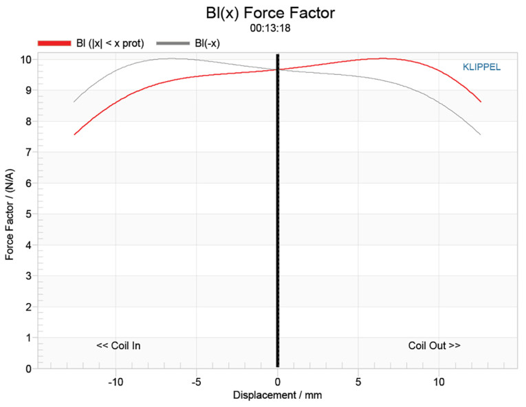
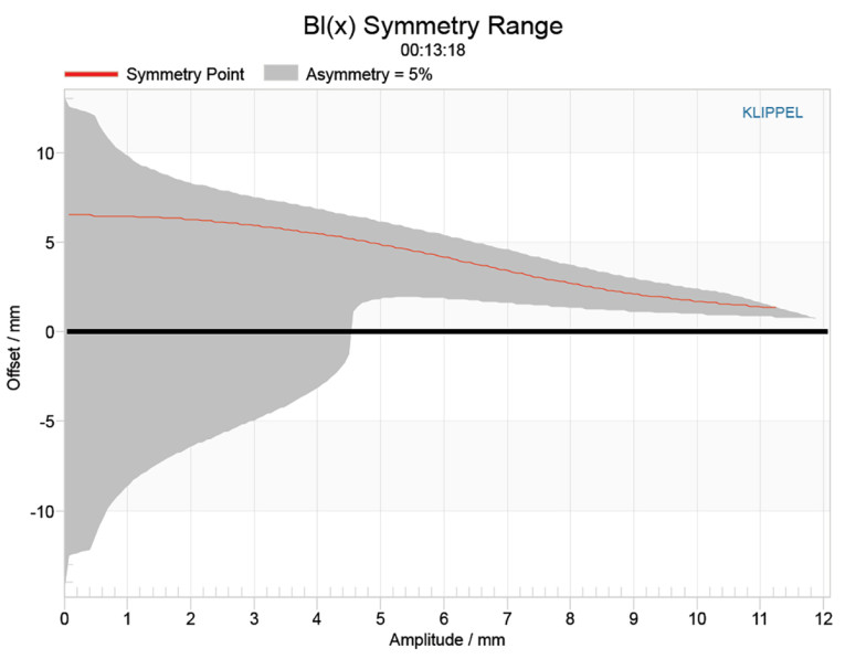
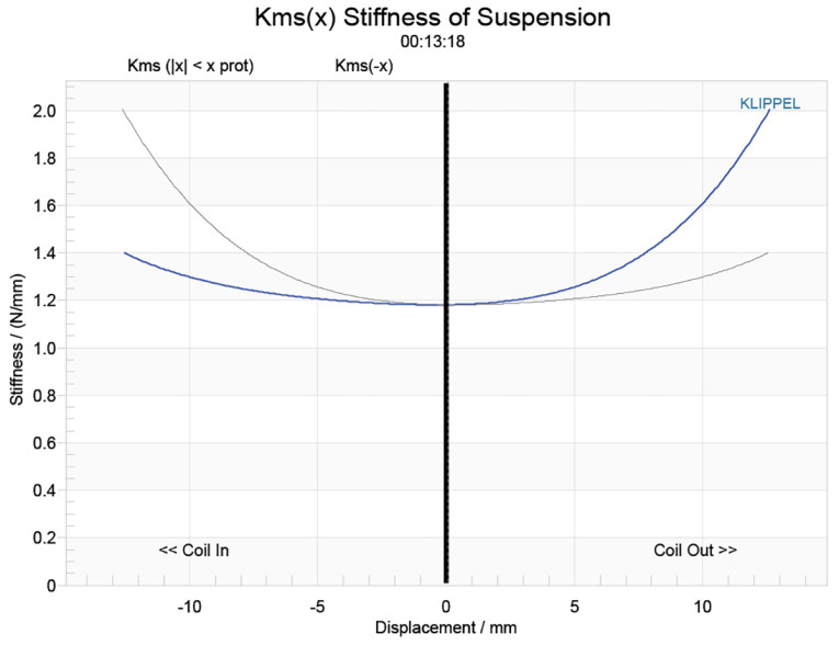
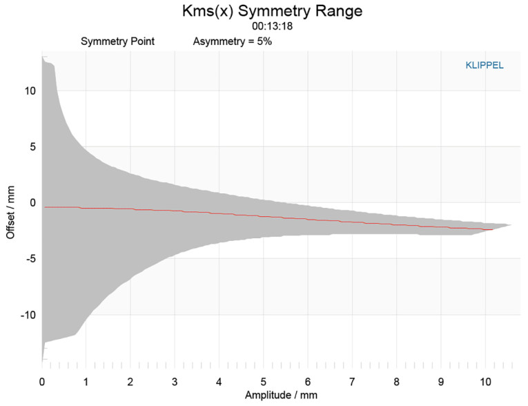
Figure 7 and Figure 8 show the Kms(X) and Kms symmetry curves for the E180HE driver. The Kms stiffness of compliance curve (Figure 7) is somewhat asymmetrical and with a small degree of rearward (coil-in) offset. The Kms symmetry range curve (Figure 8) exhibits small 1.5mm coil-in (rearward) offset at the 6mm excursion point, increasing to 2.4mm at the 10mm excursion point.
Displacement limiting numbers calculated by the Klippel analyzer for the using the full-range woofer criteria for Bl was XBl @ 82% (Bl dropping to 82% of its maximum value) equal to 11.8mm for the prescribed 10% distortion level. For the compliance, XC @ 75% Cms minimum was 9.7mm, which means that for the Dayton Audio woofer, the compliance is the more limiting factor for getting to the 10% distortion level. However, if we use the less conservative 20% distortion criteria, XBl @ 70%>12.6mm and XC @ 50% >12.6mm, showing the Bl number close to the physical Xmax of the driver.
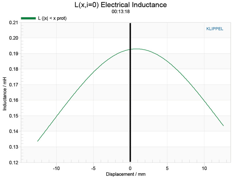
Figure 9 gives the inductance curve Le(X) for this transducer. Motor inductance will typically increase in the rear direction from the zero rest position as the voice coil covers more of pole in a conventional motor, which is not what you see in the graph, mostly due to the copper sleeve shorting ring on the pole piece. More importantly, the inductive “swing” from maximum inductance to minimum inductance from 12mm coil-in to 12mm coil-out is 0.08mH, which is very good.
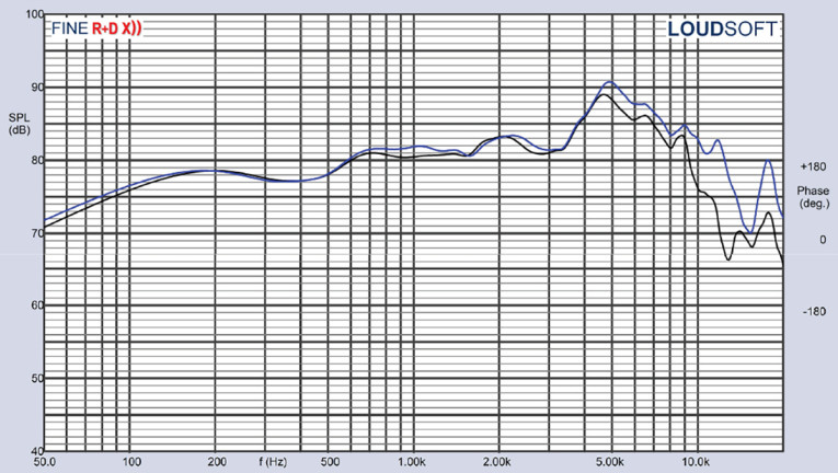
For the remaining test procedures, I mounted the E180HE subwoofer in a foam-filled enclosure that had a 20”× 8” baffle and then measured the device under test (DUT) using the Loudsoft FINE R+D analyzer and the GRAS 46BE microphone (courtesy of Loudsoft and GRAS Sound & Vibration) both on- and off-axis from 200Hz to 20kHz at 2.0V/0.5m normalized to 2.83V/1m, using the cosine windowed FFT method. All of these SPL measurements also included a 1/6 octave smoothing.
Figure 10 gives the E180HE-44 on-axis response, indicating a fairly smooth rising response with no break-up modes or peaking out to about 3.6 kHz, with a 7dB peak in the response at 4.7kHz, where it begins its low-pass roll-off. Obviously this 7” subwoofer is indeed suitable for full-range applications.
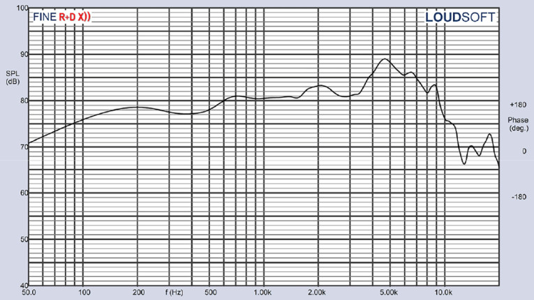
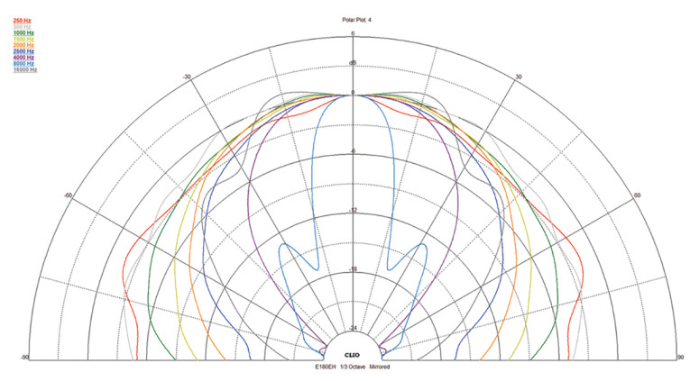
Figure 11 displays the on- and off-axis frequency response at 0°, 15°, 30°, and 45°, -3dB at 30° with respect to the on-axis curve occurs at 2.2kHz, so a cross point in that vicinity or lower should be work well to achieve a good power response, again validating the full-range aspect of the long excursion subwoofer. While I have been offering this method for approximating a crossover frequency that will yield an appropriate power response, the CEA2034 sound power directivity index is by far the most revealing methodology for determining this.
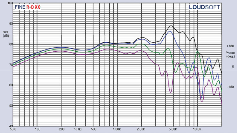
45° = purple)
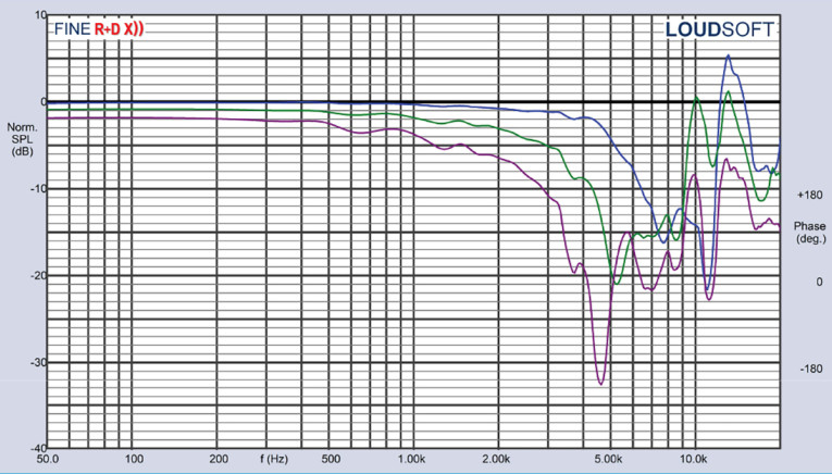
Figure 12 gives the normalized version of Figure 11. Figure 13 displays the CLIO pocket horizontal polar plot (in 10° increments) for the Dayton Epique 7” woofer. And finally, Figure 14 gives the two-sample SPL comparisons for the E180HE, showing a close match to within 1.0dB to 1.5dB throughout its operating range.
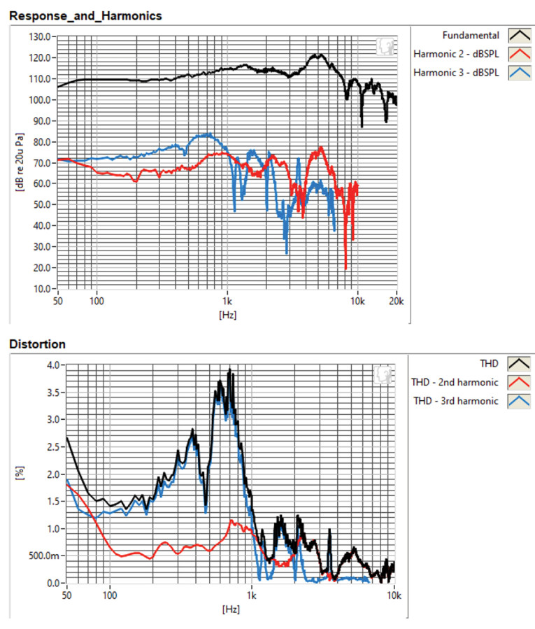
For the remaining series of tests on the Epique E180HE-44, I employed the Listen, Inc. SoundCheck AudioConnect analyzer and SCM microphone (graciously supplied to Voice Coil by the folks at Listen, Inc.) to measure distortion and generate time-frequency plots. For the distortion measurement, I rigidly mounted the 7” driver in free-air, and set the SPL to 94dB (my criteria for home audio transducers) at 1m (12.1V) using a SoundCheck pink noise stimulus. Then, I measured the distortion with the Listen microphone placed 10cm from the driver. This produced the distortion curves shown in Figure 15.
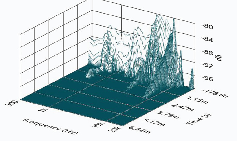
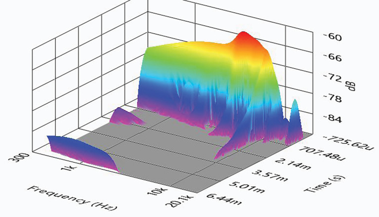
Next, I engaged the SoundCheck software to get a 2.83V/1m impulse response for this driver and imported the data into Listen’s SoundMap Time/Frequency software. Figure 16 shows the resulting cumulative spectral decay (CSD) “waterfall” plot. Figure 17 shows the Wigner-Ville plot (chosen for its better low-frequency performance).
Looking at all the data I collected for the new Dayton Audio Epique 7” carbon fiber cone shows this driver to be in a category all its own. It produces good low-frequency performance for a 7” driver, and indeed is capable of being utilized in two- and three-way designs. Given the overall design and build quality, this is a well-crafted product specifically intended the compact two-channel, home theater, or studio monitor market. For more information, visit www.daytonaudio.com and www.parts-express.com. VC
This article was originally published in Voice Coil, May 2022.