Measurement of Sound in 3D Space
In IEC 60268-21:2018 there is a totally new section that addresses, in my view, one of the biggest limitations to practical loudspeaker measurements—namely the anechoic chamber. These new standards address the measurement environments and probably the most significant change is the move away from the anechoic chamber and toward defined acoustical environment and the target environment — as in a car’s cabin. And importantly, for the first time the standards specify the positioning of both the loudspeaker and microphone, in the X, Y, and Z planes — using spherical coordinates so at last we know what and where we are measuring.
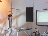
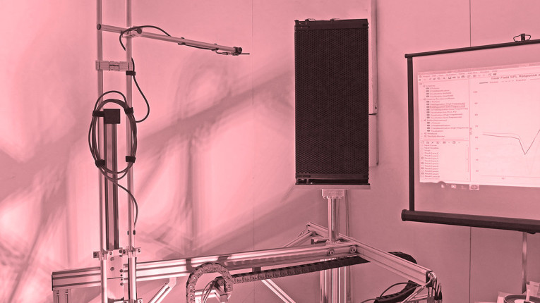
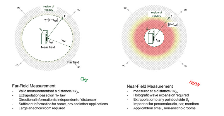
Measurements can now be made in a 3D space in both conventional anechoic and non-anechoic rooms (Figure 6). Using holographic wave expansion we can predict the far-field performance from the near-field response(s), allowing measurement of the radiated power over a specified angle or coverage. This subject is covered in more detail by AES56 (the AES standard on acoustics — Sound source modeling — Loudspeaker polar radiation measurements).
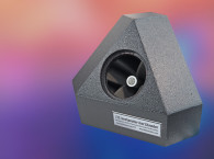
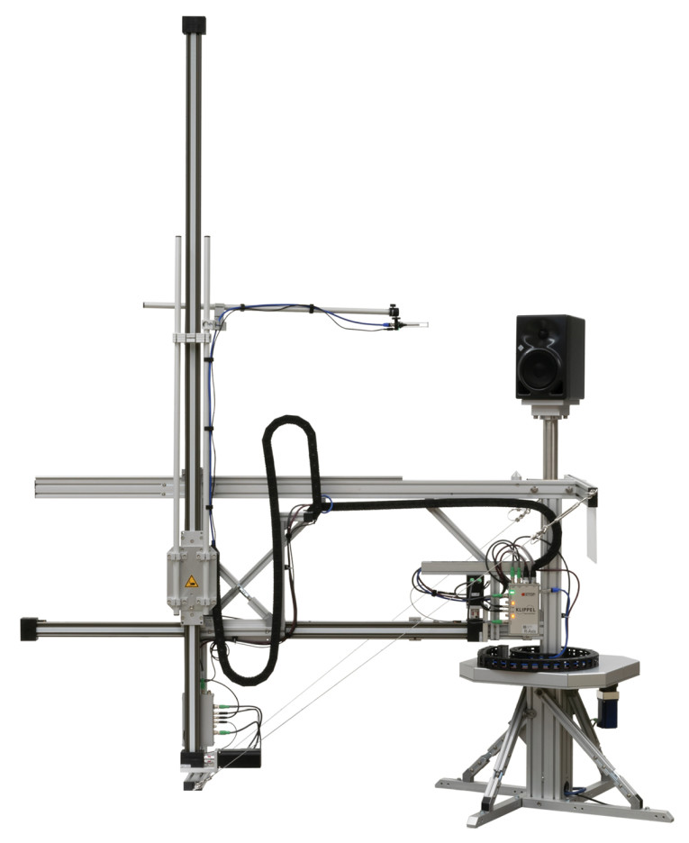
An example of this technique is the Klippel Near Field Scanner (Photo 2), which is a mechanical scanner that moves a single microphone around a loudspeaker system, or an individual transducer mounted in a baffle to effectively generate a “balloon measurement.” The main advantage of this technique is that this can be done in a normal room, while the main disadvantage there is no reduction of sound from the loudspeaker so it can be a noisy process.
Measurement of Sound in Production Environments
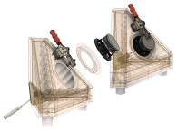
In IEC 60268-21:2018 and IEC 60268-22:2020, an interesting option is allowed beyond the ubiquitous IEC baffle and Type A or B test cabinets, which require the use of an anechoic chamber. A chamber such as the Tetrahedral Test Chamber as shown in Photo 3, may be used for end-of-line testing and relative measurements by generating a defined air load and radiation condition at the front of the transducer.
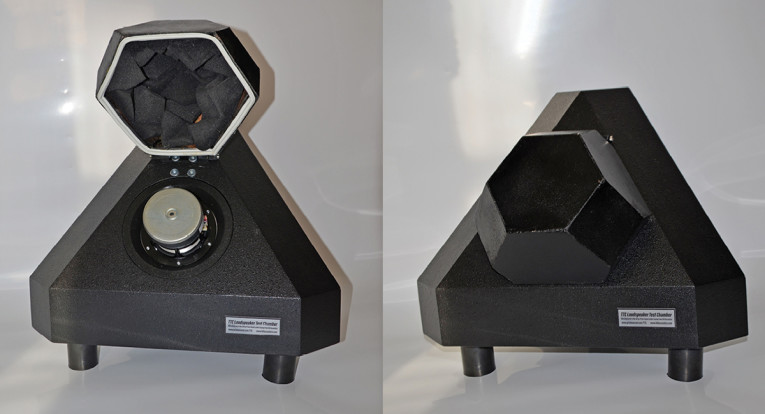
An additional chamber at the rear side of the transducer can be used to provide additional noise isolation or to consider the influence of the air volume of a sealed box in the target application.
The Audio Engineering Society (AES) issued AES73id-2019 information document on the subject of loudspeaker comparison chambers includes an appendix on measurement uncertainty, again part of these standards.
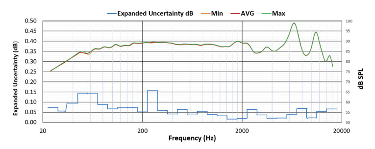
Using the concept of a measurement system’s total uncertainty budget, it is possible to accurately determine loudspeaker measurement system tolerance. This is based upon the usual 95% confidence level of the individual linear contributions of the separate deviations (e.g., a microphone, analyzer, positioning, etc.). An example of such a result is shown in Figure 7, where the uncertainty of the measurement is plotted in addition to the usual SPL axis vs. frequency.
AES73id brings to these standards the concept of an Uncertainty budget, analogous to the gain budget in Mobile Telecoms, and develops a methodology for demonstrating this so that at last we can truly have confidence in our acoustic measurements.
Voltage Sensitivity
Another — and in my view overdue — update, is the change from Power to Voltage in the definition for sensitivity measurements. As is well known to the design community, the impedance characteristics of a loudspeaker driver unit is often far from flat — this results in a variable amount of power being absorbed or consumed by an individual transducer.
The change to voltage drive reflects the reality of modern design where power is no longer (and in truth has not for an awfully long time) been matched between components but rather, the amplifier typically has a much lower source impedance than the load. This also reflects the increasing use of DSP/amplifiers, which are effectively immune to impedance loading effects.
IEC 60268-22:2020
The IEC 60268-22:2020 standard is arguably the biggest change and focuses upon loudspeakers where access is available to the electrical and or acoustical surface. This allows us to assess the behavior of a loudspeaker in both the small signal and large signal domains, as well as consider the acoustical boundary conditions in which a loudspeaker is operating.
As IEC 60268-22 does consider the internal workings of a loudspeaker and incorporates much of the recent advances in loudspeaker theory, we have access to and knowledge of the internal functionality (if not the underlying design) of these components, we can use this “a priori” knowledge to go from causes to effects. Of course, a modern loudspeaker standard still requires the electromagnetic-mechanical parameters, indeed the large signal parameters are an extension of them (Figure 8).
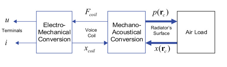
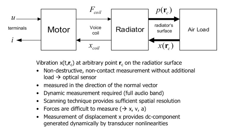
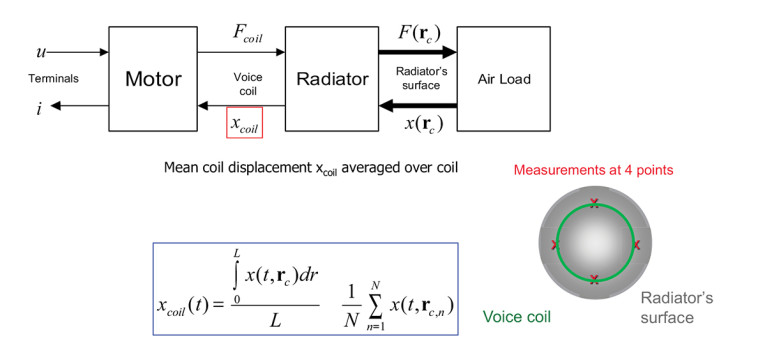
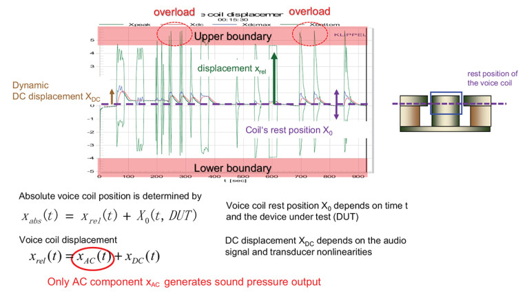
So, it is appropriate to start with these parameters. However, the measurement methods have been expanded to include those in 60268-21 plus vacuum. Along with laser sensors and scanning of the diaphragm, together these allow the measurement of the voice coil displacement and other state variables that depend for their value upon various factors, such as displacement (x), current (i), and temperature (tv), as shown in Figures 9–12.
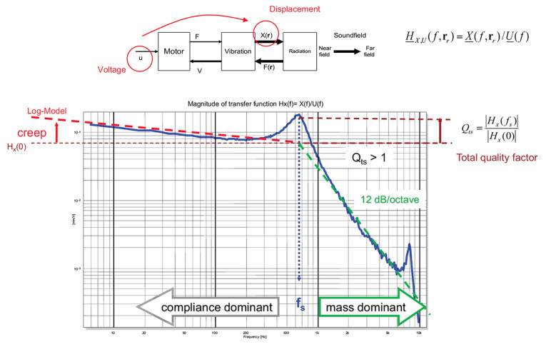
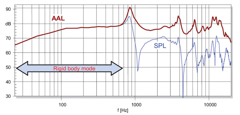
The calculation of the Accumulated Acceleration Level (Figure 13) can in turn can be used to understand the breakup modes in a diaphragm.
An important section is now devoted to this critical aspect starting with: the well-known parameter Bl translates to Bl(x), where (x) is the displacement term is shown as Figure 14.
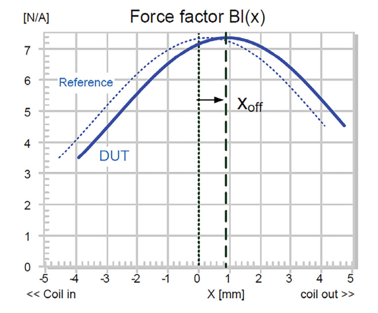
So, while in previous standards we had to use the small signal parameters from the well-known Thiele-Small set, IEC 60268-22 extends these to include state variables, such as displacement (x), with examples of particular interest being Bl(x), Cms(x), Le(x).
This is because Cms although mathematically useful is less useful to a transducer designer than its inverse Kms and arguably all are less useful until extended into the nonlinear or large signal domain, where compliance is inverted to become stiffness Kms(x), a measurement of Cms with respect to displacement (x), then Le, the lossy impedance rise of a loudspeaker can be predicted through the use of various models from W. M. Leach, J. R. Wright, and K. Thorburg While Le(x) extends this using the displacement (x). Modal Analysis and Rocking modes are particularly troublesome for small high throw transducers, and are added together with measurement methods. Thermal characteristics together with mechanical fatigue and methods of measurements for these are also included.
IEC 63034 Is About Microspeakers
Crazy though this may sound, until the IEC 63034 standard there was effectively nothing suited to microspeakers. These are defined as speakers where the size of the radiating element (diaphragm or another radiator) is no greater than 40mm. Of course, compression drivers and high-frequency drivers (tweeters) are specifically excluded.
We may ask why not apply IEC 60268-5, IEC 60268-21 or IEC 60268-22 to microspeakers? It is simply because their typical conditions of use are smaller than the usual measurement range. Where typically speakers are measured at 1 meter, microspeakers are usually used at 10cm distance, voltage ratings are below 5V, but they have extreme displacement for their size.
The IEC 63034 document specifies the characteristics of microspeakers as well as the relevant test methods for these devices using steady-state sinusoidal signals, sinusoidal chirp, multitone, or noise. The main characteristics include, but are not limited to, impedance, displacement, amplitude frequency response, distortion, and power handling. Considerations are in place for its small size, light weight, low handling power, short listening distance, and difficult working conditions. These take into account the working environment, test signals, equipment, preconditioning (acclimatization, pre-loading). Typical measurements include:
- Impedance Curve (rated impedance), Small signal parameters (Fs, Rdc, Le, Q, Mms, Cms, Rms, Bl, etc.)
- Displacement (peak/bottom, DC, max), amplitude, distortion (THD, IMD, HOHD)
- Input voltage/ electrical power, environmental testing (temperature/humidity)
- Stray magnetic fields
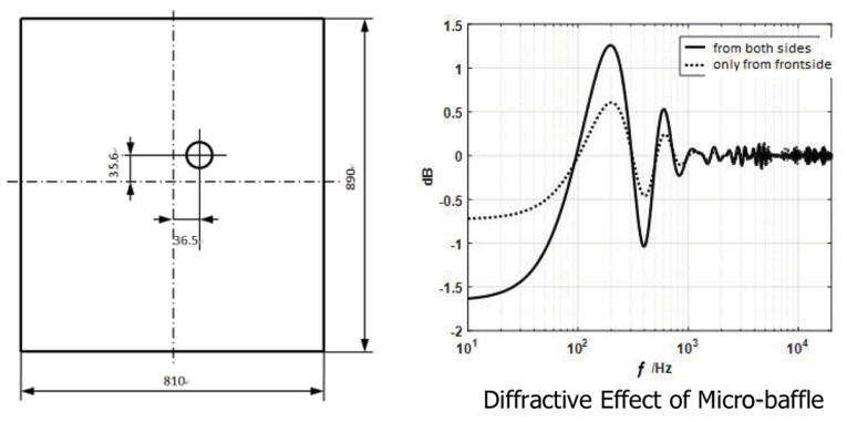
Although an improvement over the usual IEC Baffle of 1650mm × 1350mm, a baffle that measures 810mm × 890mm is still pretty big. Especially as this is for measuring microspeakers at 10cm (Figure 15).
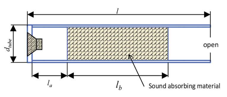
For production, a plane wave tube is introduced (Figure 16). Plane wave tubes have long been used to provide standardized measurement results. Fortunately, alternatives are available and have been standardized in the IEC 60268-21 and 22 standards, and also by the AES in AES73id-2018.
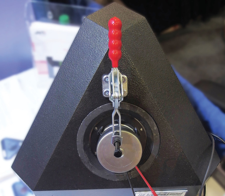
In the AES73id standard the concept of a defined acoustic environment has been advanced, some of these are capable of measuring at 10cm while minimizing uncertainty to below ±0.5dB from 20Hz upward dependent upon the transducer being measured. A suitable example being used for microspeaker work is the Hill Acoustics TTC350 shown in Photo 4.
Also, in AES73id the concept of defining the total measurement uncertainty is further developed from a single point or frequency at which it is measured to encompass the measurement uncertainty over a given frequency range along with a methodology for general application.
This enables us to more closely define what we are measuring in an amplitude response over a range of frequencies in terms of the variability. Of course, this is not of much use until its matched with an appropriate methodology for the measurements themselves, capable of a high degree of accuracy/consistency.
This article highlights just some of the many changes to the standards that bring them up to date. Taken together these standards in effect define a solid base level with which every engineer or specifier of loudspeakers should be familiar.
Author’s Note: I would like to thank Wolfgang Klippel and Prof. Shen of Nanjing University for permission to include many of the figures in this article.
Resources
W. Klippel, “Electrical and Mechanical Measurements of Loudspeakers and Sound System Equipment: Tutorial to a New IEC Standard,” 2016, www.klippel.de.
“Meter,” National Institute of Standards and Technology, updated June 2021, www.nist.gov/si-redefinition/meter
“What is Metrology,” NCSL International, https://ncsli.org/page/WIM
This article was originally published in audioXpress, October 2022.
Read Part 1 of this article here.
 About the Author
Geoff Hill, inventor of the Tetrahedral Test Chamber (TTC) and CTO at Hill Acoustics, has been working in the loudspeaker and audio industry for more than 40 years. He is Chair of the AES SC-04-03 Working Group on loudspeaker modeling and measurement and a member on the IEC Working Group TC 100/TA 20/PT 60268-22. He is also the author of Loudspeaker Modelling: A Practical Introduction. Geoff welcomes your comments and can be contacted via email.