The roots of the Tetrahedral Test Chamber (TTC) goes back years, stemming from when I worked as a development engineer for Goodmans Loudspeakers, a respected British loudspeaker manufacturer, back in the mid-1980s. It was at Goodmans that I first designed and subsequently needed to measure loudspeaker drive units professionally.
2m × 2m x 2m.
My Early Days Using Anechoic Chambers
I had just joined Goodmans as a development engineer and left my position at Bowers & Wilkins (B&W), another highly respected British loudspeaker manufacturer, where I had been an electronics test engineer. At that time Goodmans’ offices and factory moved to an industrial area in Hampshire, England. There, a new anechoic chamber was constructed, a massive steel monstrosity, 7m on a side with huge fiberglass wedges—some of which came from their old Downley Road chamber in Havant, Hampshire.
Access to the new chamber was via a stairway, which turned through 90 degrees before ascending roughly one-third up the structure of the chamber. So, it was a real pain to get anything in and out. Difficult and awkward does not even come close to describing it.
Entry to the Goodman’s chamber was through a hermetically sealed 12” thick steel door. The two doors were constructed so that it was impossible to get out of the chamber if the doors were closed! As a result, it was company policy that no one person could ever work alone in the chamber, without another person always stationed outside.
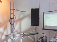
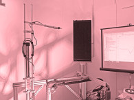
The inner chamber door formed part of a 2PI baffle, and led onto a perforated steel plate catwalk, which caused severe acoustic reflections back to the measurement microphone. The catwalk allowed entry onto the steel mesh, which was strung side to side and front to back over the entire working area of the anechoic chamber. The mesh floor would bounce up and down as you walked around the chamber. This impacted the repeatability of the microphone and the loudspeaker measurement positions, rendering them unstable and inaccurate in X, Y, and Z planes!
However, these problems paled compared to the challenge of calibrating the chamber. Lots of care had been taken to ensure an adequate air flow rate so that someone could survive in the chamber should they get locked inside, I always thought it a pity that they did not consider that this same ventilation system made an ideal 15Hz organ pipe, resonating away at 85dB to 90dB SPL re 20uPa, of course it produced this level throughout the entire chamber!
It was necessary to provide a reference loudspeaker to calibrate the chamber, so I selected one with as flat and as uniform a response as possible. We had this independently verified at great expense at the National Physical Laboratories in Teddington, so I was surprised to learn that the standard method for qualifying the chamber was just to feed pink noise into this speaker set up roughly equidistant of the center of the chamber—measuring the SPL in third octaves at 1m and then progressively increasing the distance along a single measurement line. Anechoic behavior being confirmed by measuring less than ±1.5dB deviation of one-third octave data, the low-frequency cut-off was similarly determined by the increasing error in this chamber once this exceeded 3dB.
The -3dB cut-off frequency was around 100Hz. This was at a cost of £250,000 and the chamber took up the space of a small house and was only able to measure down to 100Hz. Let us look at why a 100Hz low-frequency cut-off is a practical limitation that cannot be overcome using a conventional anechoic chamber!
We know the speed of sound in air ~343m/s, the wavelength is speed of sound/frequency (e.g., 343/1000 = 0.343m for 1kHz):
343/100 = 3.43m for 100Hz
343/10 = 34.3m for 10Hz
In order to fully absorb a wavelength, the absorption material needs to be over a half wavelength long, so as the wedges in this and most chambers are less than 2m long this sets the cut-off frequency for most chambers at around 100Hz.
I was shocked when I realized that we had built a chamber the size of a small house so that we could measure 5” (125mm) and 6.5” (170mm) loudspeaker drive units that went down to 70Hz, which was below the low-frequency cut-off of the chamber.
End-of-Line Testing vs. Anechoic Chambers
It was also at Goodmans that I first became aware of just how inadequate the end-of-line and QC test stations were in comparison with the anechoic chamber, even with the problems that I already explained. It was shocking to see how little resemblance there was between the measurements made in the anechoic chamber and the end-of-line tests.
I well remember being called upon to “put limit lines” on a test for a loudspeaker driver being tested by an Ortofon P400 acoustic analyzer; this stored the curves in a plug-in EPROM and had to be manually increased or decreased around a “Golden Standard” drive unit that I had previously approved in the engineering laboratory’s anechoic chamber.
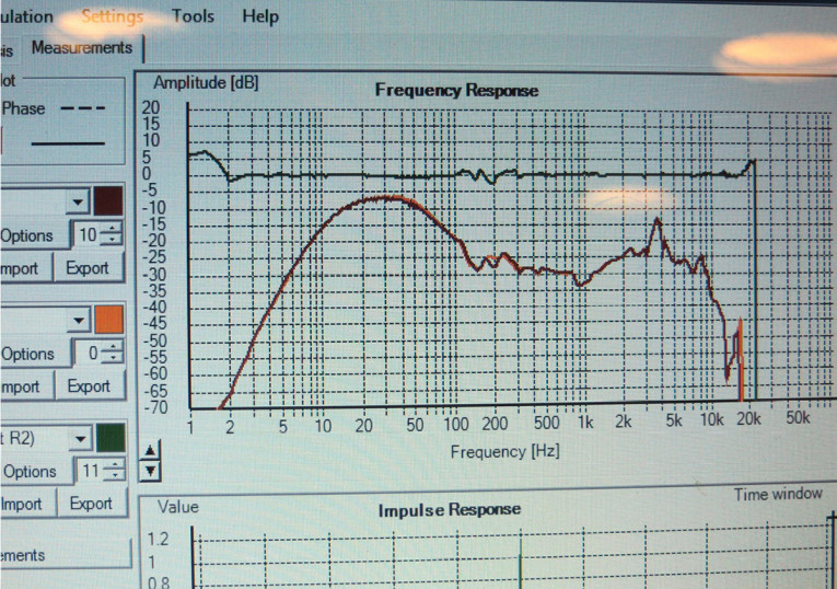
The major problem was that not only was there a significant rise at low frequencies, but also the response was peaking up and down rapidly by ±20dB or more as well!
The result was inevitable—the slightest problem or discrepancy, and “Engineering” (meaning me) was then called to the production line, to arbitrate as to whether there was a fault or not. And if so, what the cause of the problem was!
The bottom line was that the test chamber was seriously influencing the measurement — something that I would solve when designing my Tetrahedral Test Chamber (TTC).
All the line test boxes or chambers that I used or designed myself, until the TTCs, were universally inadequate and so it continued throughout my career whether at a hi-fi company, a mobile phone manufacturer, or a PA/music company.
When it all went wrong, I had to make sense of measurements sent to me by a driver supplier or a customer for approval. Often you could not even recognize the expected response of one type of loudspeaker over another. This was despite all the measurements being made by instruments able to measure better than ±0.1dB!
Giving Loudspeaker Measurements the Attention They Deserve
I must confess that at that time, early 1980s through 1990s and into the 2000s, I just accepted it as the way things were. That loudspeaker measurements were inherently unreliable and inconsistent; a view that I had held for many years! I was not alone as even today loudspeaker measurements are not given the attention that they deserve.
The rise in modern modeling and simulation has resulted in design engineers relying on the modeled response, while having little regard for the actual loudspeaker’s response, then relying on DSP as a crutch to correct suspected problems rather than working from known accurate measurements. And to make those measurements, a chamber that did not require the space and the large investment of an anechoic chamber was needed.
In my experience, after designing many anechoic chambers and test chambers, the goal is to be able to make consistent measurements. Measurement errors are caused by the physical setup, mechanical issues, variability in connections, things not being in correct alignment, and the measurement methodologies in use. The anechoic chamber does not address any of these issues. So, we should forget about the debate around marginal improvements in cut-off frequency or the lowest noise floor of the chamber and focus on our goal of making consistent measurements.
In 2011, there was a lively discussion going on within the Audio Engineering Society (AES) Standards Committee working group SC 04-03. The debate focused on the improvement of the measurements of loudspeakers in use in OEM and automotive applications. I was actively involved in these discussions. From these discussions I started to formulate and collect ideas for a book on the subject.
In 2012, I began writing my first book. As I wrote on the subject, it became increasingly obvious that designing a loudspeaker was only a part of the challenge, and a significant part was the verification of the design through measurements. Up until now, there was no acceptable way of doing this, short of the anechoic chamber. Around the same time, I was approached by Neat Acoustics here in the UK, to assist with its loudspeaker drive unit measurements. This is when I sat down and realized that I needed to resolve this problem once and for all.
The Deep Dive into Analyzing the Problems
I took all the knowledge and experience that I had gained over the course of many years and asked myself what were the best or should I say the most consistent loudspeaker measurements I had produced and why?
I quickly concluded that my most consistent measurements were made with the speaker firing toward or away from a corner of the anechoic chamber rather than using the standard baffle methodology.
Nearly all the standardized loudspeaker driver measurements required the use of a baffle, this compromises the measurement because most loudspeaker drive units are designed to be used in some form of enclosure or box. In addition, in none of the standards are the setup conditions of the baffle or the microphone defined apart from vague statements like:
“Measurements should be made in free-field conditions at such distance that the transducer/loudspeaker is operating in the far field,” and that “care should be taken to ensure consistency in setup and repeatability.”
These statements sound great in theory but truthfully, comments like this leave much unsaid and with so many different variables. For instance—How should the baffle be set up? Where should the baffle be in the chamber? Where should the test box be in the chamber? How should the microphone(s) be set up, at what angle and azimuth, at what distance(s)? With all these options, measurements become increasingly difficult to pin down precisely. This is understandable as in theory an anechoic environment should be totally free from reflected sound but in practice this is often not the case. The real problem is statements like “Care” and “Should” are hopelessly inadequate.
Anechoic measurements using a baffle are extremely unwieldy, requiring large and expensive structures. The anechoic chamber was originally designed as a general-purpose tool, which when combined with the use of baffles brings into question this whole methodology.
So how do we go about designing a test chamber that solves these issues? We must start by listing the criteria of a chamber that overcomes these problems:
- Footprint: The footprint should be a fraction of the size of an anechoic chamber. Acquisition, installation, and maintenance costs to be a fraction of those of an anechoic chamber.
- Repeatability: Must be capable of consistently stable measurements. This requires a defined geometry between the microphone and the loudspeaker under test.
- Accuracy: Must represent the tested loudspeaker’s true response and capable of measuring to the low-frequency limit of the driver. Has effective absorption for high frequencies. Have minimal modal behavior. Capable of precise and simple calibration.
- Transferability: Able to obtain comparable results between chambers. Practical and straightforward implementation. Provide a path toward future standards.
- Simplicity: Be easy to set up and operate. To have a baffle and sub baffle allowing quick changeover of loudspeakers. To have the flexibility to operate with different sizes of microphones.
The Birth of the Core Concept
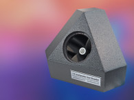
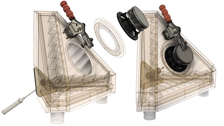
As I said before, many of the best measurements I have made have been in a corner. So, this formed the core of the physical design. I distrust complex solutions and prefer simple ones.
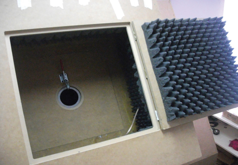
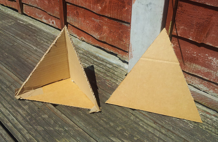
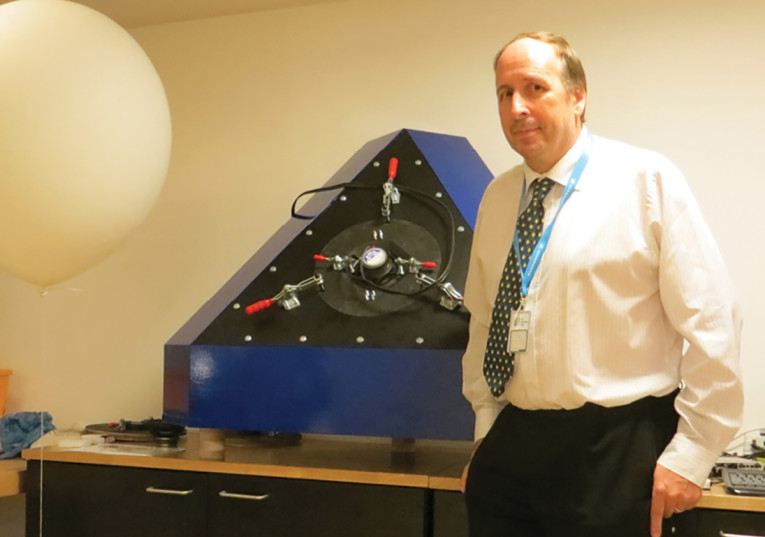
So, let us put the microphone in the corner and the speaker under test on a triangular baffle, firing sound toward the microphone. This satisfies the first criteria of keeping the structure relatively small and the second criteria with defined geometry. Thus, the core concept of the Tetrahedral Test Chamber (TTC) was born. The name is derived from a regular Tetrahedron, which is made from four identical equilateral triangles.
My first thought was “can this concept really work?” So, I reached out to a few esteemed colleagues and trusted advisors in the field of loudspeaker test and measurement and after considering my concept for a few minutes they ALL replied, “Well, I don’t know why I did not think of this.”
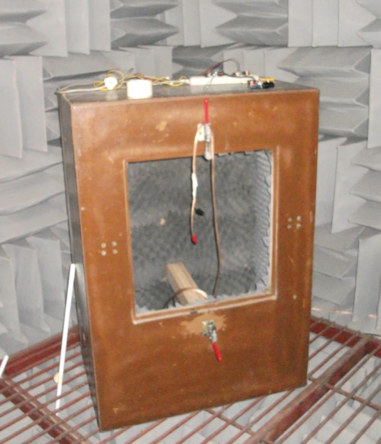
Wolfgang Klippel told me that I should publish this and get it out to the world. And then fortuitously, Neat Acoustics needed a measurement chamber and I had my chance to put the concept to the test. A few phone calls and meetings later I had an agreement for Neat to purchase the initial chamber, which has now been successfully in use for nearly 10 years.
Next I started the process of defining the scope of the project: First, Neat needed to measure five or six main chassis types from 5” through to 12” plus various size tweeters. So, this dictated the size of the chamber and I began sketching 2D CAD drawings.
In Part 2 of this article, we describe the initial launch through the refinement phase, and peer review of the concept, proving the chamber’s measurement repeatability, and its inclusion into the international standards. Then onto using the chambers in practice throughout the world. aX
Click here for Part 2 of this article.
Resources
AES73id - AES information document for acoustics — Loudspeaker driver comparison chambers
G. Hill, Loudspeaker Modelling and Design a Practical Introduction, Routledge/Focal Press, 2018.
www.routledge.com/Loudspeaker-Modelling-and-Design-A-Practical-Introduction/Hill/p/book/9780815361336
G. Hill, “A Guide for Building Your Own Test Chamber,” audioXpress, September 2020.
IEC60268-21:2018 — Sound system equipment - Part 21: Acoustical (output-based) measurements
IEC60268-22:2020 — Sound system equipment - Part 22: Electrical and mechanical measurements
on transducers
This article was originally published in audioXpress, September 2021