The impedance in each physics domain gives you the “primary” or “independent” variable divided by “secondary” or “dependent” variable, which for the electrical domain is the voltage divided by the current. The electrical domain serves as a “parent” domain, since we want to take advantage of the well-established framework here with Kirchhoff’s current and voltage laws, establishing transfer functions from circuits, Bode plots for frequency responses, using SPICE software, and so on. The downside of course being that an engineer trained purely in acoustics or mechanics might not be immediately comfortable with these circuits. We see in Table 1 how impedance is defined in the different domains and notice the similarities.
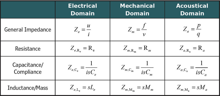
So, one can find an analogy between an electrical capacitance and a compliance, be it mechanical or acoustical, and similarly, between an electrical inductance and a mass. We will see some complex circuits later in this article utilizing this mapping, but first imagine the situation shown in Figure 1 with two springs being compressed by a common force. It should be easy enough to realize that the total stiffness will be the sum of the stiffness of each of the springs on their own. As stiffness is the inverse of compliance, we can thus calculate the total compliance as:
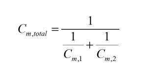
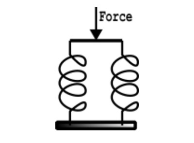
And here we see an issue. From electrical engineering we recognize this as the way to add capacitance when in series in an electrical circuit, whereas for the mechanical setup we would immediately say that the two springs are in parallel. Figure 1 illustrates a well-known issue being that you will not automatically have a “conform” depiction when mapping from one domain (such as mechanical) to another (electrical).
To have congruence with respect to series vs. parallel connections between two non-conforming domains, one can instead adapt the so-called Admittance or Mobility strategy, where impedances in one domain have admittance (inverse of impedance) analogs in the other, so that the primary variable in one domain maps to the secondary variable in the other domain, and vice versa.
The admittance analogy will ensure that series and parallel connections are retained in the electrical domain, but as with anything, there are pros and cons to both the impedance analogy approach and the admittance ditto. I typically work consistently with the impedance analogy, but sometimes the analogy circuits are much easier to make in the admittance analogy first, and then subsequently I convert to the impedance analogy. The choice will also be affected by the transductance principle for the transducer, meaning how energy is converted between domains, which is different between a standard “electrodynamic” driver and for an electrostatic transducer as examples, and we may touch more upon this in a future article. Finally, it should be noted that special cases exist for which only one of the two approaches is possible.
Degrees of Freedom
One important aspect of a lumped model is that it has a limited number of degrees of freedom, so there is only so much of the continuum physics aspects of a real transducer that are captured. Oftentimes it is not the lumped aspect itself that limits the information that can be extracted from a model, but instead the number of components that were put into the model in the first place.
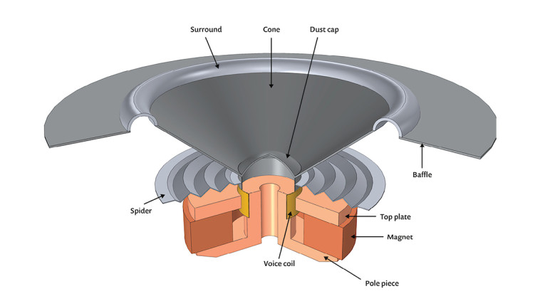
For example, looking at the typical lumped circuit for a loudspeaker, as shown in Figure 2, utilizing the Impedance analogy strategy throughout, it is seen that all the moving mass of the loudspeaker resides in only a single inductor, and the total stiffness from primarily the spider and the surround sits in a single capacitor. This limits the effects that would be seen in a more elaborate lumped model, where the basket was included as perhaps two added compliances between the magnet and the spider, and the spider and the surround/enclosure, respectively, with each their associated mass, to capture via the lumped model how the reaction force in the magnet systems displaces the individual parts of the driver differently.
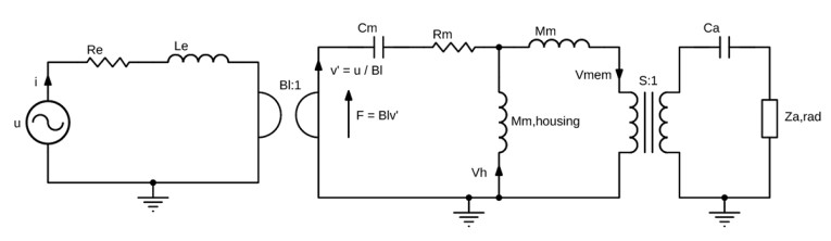
Note however, that in Figure 2 a component has been added for the mass of the cabinet and magnet system. The reaction force will displace the magnet in the opposite direction of the voice coil, and while the effect is small for a traditional loudspeaker, we will see later that for some applications it should not be ignored.
Balanced Armature Receivers
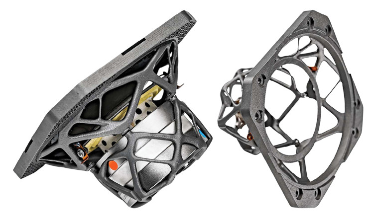
One could go straight to focusing on having a very rigid basket, such as has been sought by, for example, Børrensen [1] using topology optimization (a topic for a later article), see Figure 3, along with a heavy and stiff cabinet to have the physical setup match the simpler traditional lumped model for a loudspeaker. But I think it is a good idea to have more components in the initial model, and then from there estimate where to stiffen the basket, or in general investigate the relevant variables in a model complex enough that it does not lump several of them together.
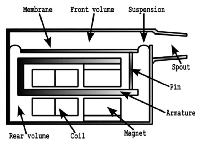
While the basket and the cabinet of a loudspeaker certainly does flex and move due to reaction forces, there are transducers for which this effect is much more important, and one such transducer is the Balanced Armature Receiver (BAR). In Figure 4 a cross-section of the BAR is shown for a so-called Single version since it has a single membrane. The armature is magnetized by an AC current in the coil, and as the armature is suspended between magnets, a displacement can be obtained via this “moving iron” setup.
A principle lumped model can now be presented here that captures the relevant physics; the electrical behavior, the mechanical behavior, and of course the most important of them, the acoustical outputs, in the respective domains represented by the lumped components. The model considers the effect of reaction forces possibly displacing the whole receiver housing and how this modifies the acoustic pressures. The sequential coupling from electrical to mechanical is two-way, and the same goes for the mechanical-acoustical coupling. This means that one could investigate the induced voltage and acoustic pressure resulting from vibrating the housing, and that could be of interest to hearing aid manufacturers and earphone companies. The lumped model is shown in Figure 5 with the individual components for each relevant part of the Single BAR.
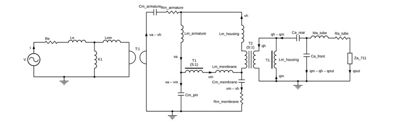
The lumped circuit for the Single was made in Spring 2022 and components were fitted up against an existing finite element of the Single BAR made by COMSOL and can be found in its Application Library [2]. Note that all fitting here was “physical” in that component values were found via geometry and material parameters, instead of simply doing a numerical fitting.
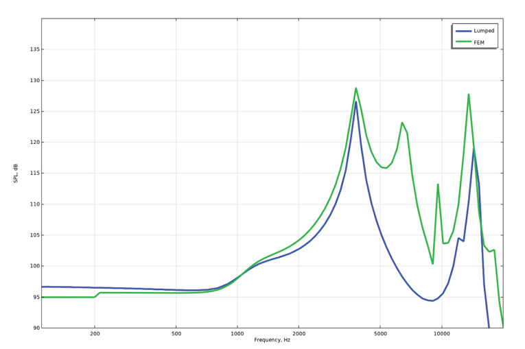
The agreement between the lumped model and the finite element model is good across all involved physics up to a frequency where lumped modeling requires more degrees of freedom to capture the relevant effects, with more details on my own blog post on the model [3], and with the sound pressure levels for the two models compared in Figure 6.
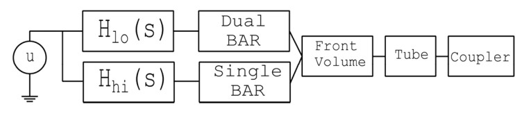
With such a model, the output from more complex setups can be evaluated quickly, such as for the Shure SE535 earphone shown in Figure 7. The earphone utilizes two BARs — a Single and a Dual — and it incorporates a crossover filter between the two. Their combined output into, for example, a front volume, a tube, and a coupler, can now be evaluated in a matter of a few seconds, and the model will encapsulate aspects such as complex electrical impedance and complex velocities for each of the masses. Design changes are easily made via the available parameters for materials and geometries, and so a parameter sweep or even parameter optimization can be used for exploring the solution space.

With the combination of a Single and a Dual, one now of course has the option to optimize each of them for their intended output with respect to their individual frequency responses, instead of having the usual compromises found for a lonely receiver, Single or Dual, found for example in a hearing aid. With two different receivers in the earphone, the Single BAR can now be modified to extend further up in frequency, whereas the Dual BAR can handle the lower frequencies on its own. The block diagram shown in Figure 8 outlines how the different lumped sections can be connected for evaluating the coupler pressure resulting from an applied input voltage.
Circuit Calculations
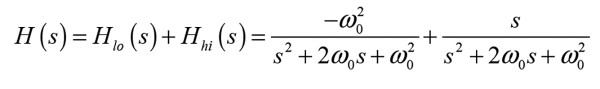
The transfer functions for the crossovers could be something like a second order Linkwitz-Riley type (of course I have no idea what type of filter is being used), and so mathematically it would be expressed as:
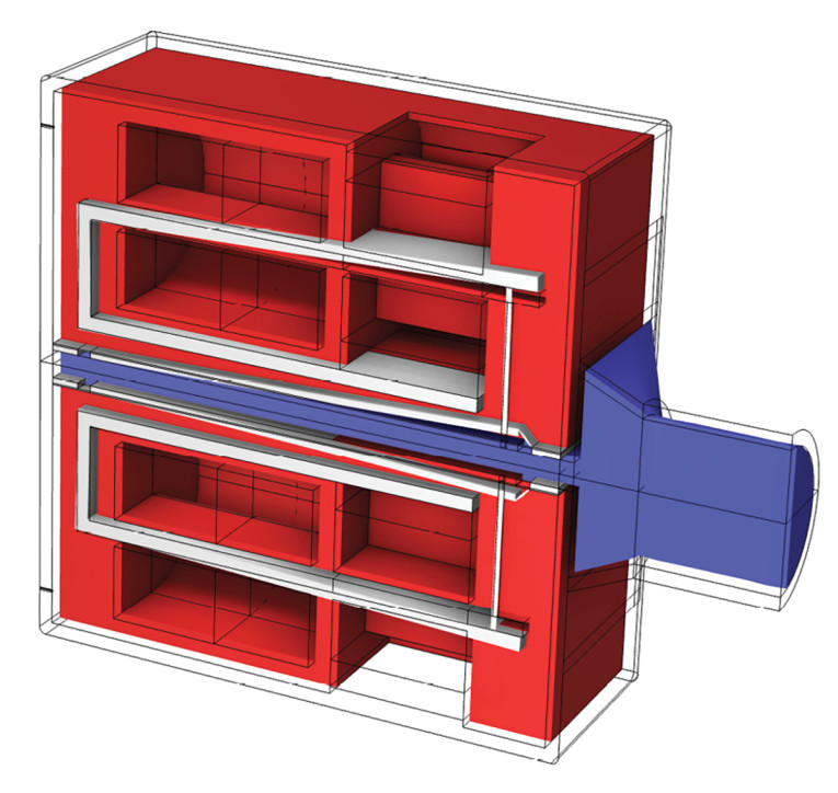
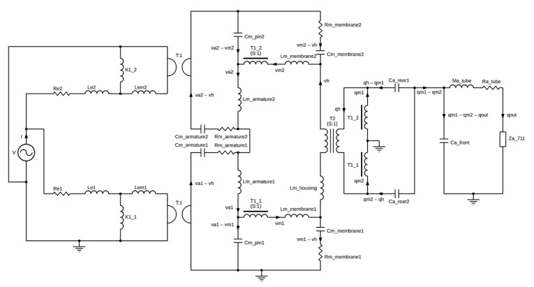
For the Dual BAR the lumped circuit is seemingly missing, and so one could go by way of creating a full finite element model in COMSOL Multiphysics as shown in Figure 9. However, I have also made the Dual BAR lumped circuit, which is presented here for the first time in Figure 10. Again, there is very good agreement between the two models, and it is my hope that my new lumped models will benefit transducer and hearing aid engineers in their development work.
The presented circuits have complete couplings between each intersection, and perhaps that can lead to new utilization ideas, such as counting steps based on the induced voltage from the housing moving. These circuits are very powerful for transducer engineers, since once they are established, a lumped model runs in about one second, while the more complex finite element models can have computation times that can be three, four, or even five orders of magnitude longer. That means that one should start out with the lumped model for the overall estimates and parameter studies, and then continue with the finite element model for the refinements at higher frequencies as needed.
Concluding Remarks
I am a big proponent of modeling-based engineering. Not any one modeling type in particular; it could be analytical expressions, lumped models, transmission line models, finite element models, or hybrid models that combine the aforementioned types. For me, it is very difficult to discuss designs and inner workings of a product without any type of model characteristics. The lumped modeling method described in this article can often give engineers a very good representation of the product that they are working on, and it helps immensely in meetings to have something concrete to present and discuss. The lumped model type, like any other, has its limitations, but it is often the best place to start when starting out on a new design, and as has been demonstrated, you can cover some complex designs and still have an extremely quick design change cycle.
In one of my next articles, we will look at a client case where a transducer setup was modelled using the lumped approach, and how the client can do some of their design explorations via delivered analogy circuits.
Author Acknowledgements: Thanks to Gojko Obradović (Principal Hardware Architect Acoustics, Oticon A/S) for suggesting the Shure earphone as an example.
Resources
[1] “Børrenson M1: New Flagship Loudspeaker from the Danish Company,” Fidelity Magazine, www.fidelity-magazine.com/borresen-m1
[2] “Balanced Armature Transducer, Comsol, www.comsol.com/model/balanced-armature-transducer-61741.
[3] R. Christensen, “#40: Balanced Armature Receiver - Lumped Parameter Modeling (Preprint, Part 1), June 11, 2022,
www.acculution.com/single-post/040-balanced-armarture-receiver-lumped-parameter-modelling-preprint-part-1
This article was originally published in audioXpress, March 2023