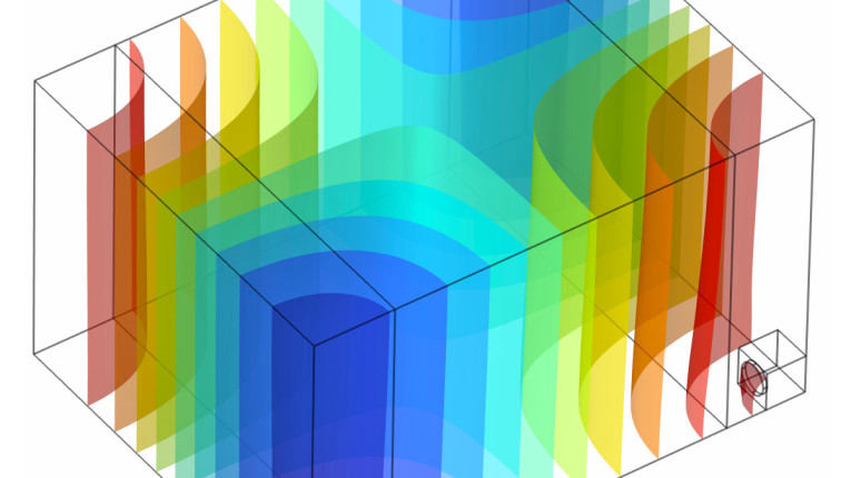
The sound field in a room at low frequencies is one of the most discussed topics on audio forums. Rooms have different layouts, and users have different types of loudspeakers and subwoofers, so placement and settings are crucial for achieving some desired sound distribution in the room. Issues such as modes being excited and leading to resonances in the response that vary with position can be addressed by placing multiple subwoofers and adjusting their output in amplitude, phase, and overall time delay. Basically, the problem is typically treated as an optimization problem for some objective function related to sound pressure level (SPL) variance across several listening points around the seating area. However, in this article a different strategy is explored for which the modes are simply not excited by, in a sense, converting the room into a tube via the so-called double bass array (DBA) layout.
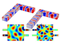
We have encountered room modes in a previous article of mine [1], and so without going into any mathematics here, room modes can be described as solutions to the wave equation when no sources are present, see Figure 1 for an example. Assuming hard walls and no losses in the room, these sound fields would be self-sustained if somehow excited, and so it is natural to expect that under forced conditions, such as having loudspeakers driving sound in the room, these modes will affect the response at all listening positions.
Corner Placement
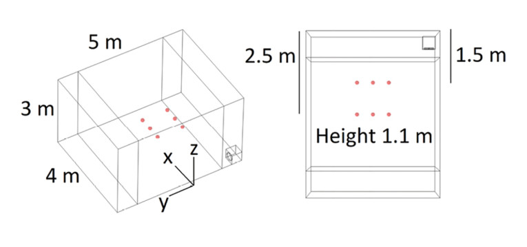
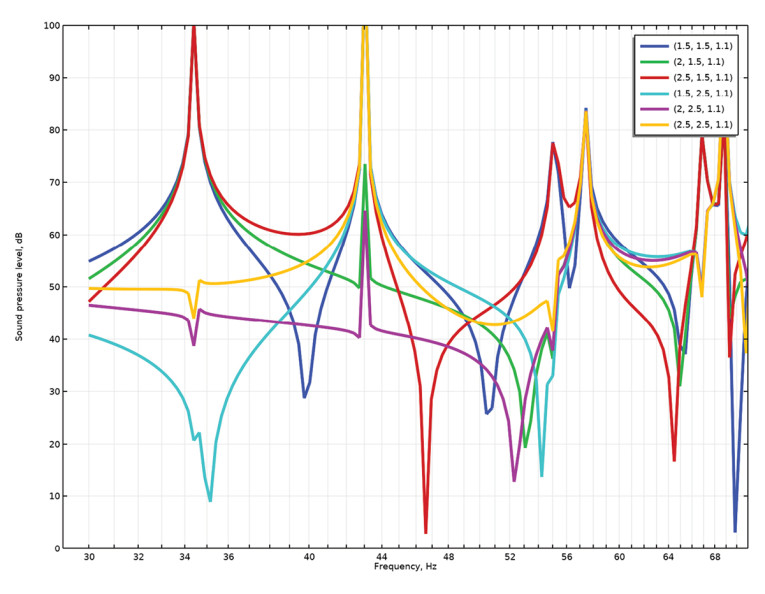
If we place a single subwoofer in a corner, as shown in Figure 2 where six listening points of interest are indicated, we will get a low-frequency response, as shown in Figure 3, where for now the subwoofer has a constant acceleration. The peaks and dips in the response are mainly seen near the modal frequencies already found. So, different listeners will not experience the same low-frequency sound, and most of them will probably be dissatisfied with the response. This is a completely undamped room, so in practical rooms the situation may be somewhat better, but still the response is problematic.
Different strategies have been suggested to alleviate the problems with in-room sound fields at low frequencies, where the modal density is low, such as adding multiple subwoofers to balance out the response with for example Earl Geddes’ paper about multiple subs [2], where multiple subwoofers are placed strategically with their level and phase settings possibly with some additional equalization. The strategy is based on decorrelation of the subwoofers to achieve a more smooth in-room response, and in general the more subwoofers you have in a room, the smoother it is.
This was explored numerically by Harman [3], where the sound field in a cuboid was optimized over several seating configurations for various subwoofer layouts regarding number, positioning, gain, delay, and such. Some guidelines are given for a realistic number of subwoofers, and the overall outcome is like that of Geddes, in that three to four subwoofers with individual adjustments will certainly outperform just a single subwoofer.
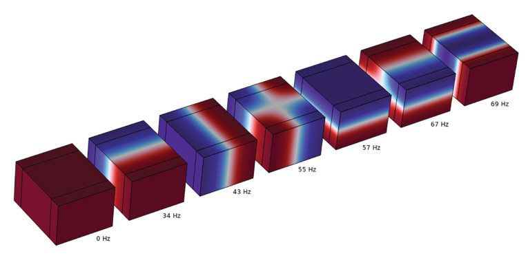
It should be noted that a mode does not equate a resonance. A mode is calculated without consideration of sources, whereas resonances and anti-resonances are what can be observed for a given output transfer function with one or more sources, possibly of different types (monopoles, dipoles). This can be seen at, for example, the frequency of 34Hz, where for some of the six microphone points there is a clear resonance, whereas for other points there is just a smaller wiggle and for one there is an anti-resonance.
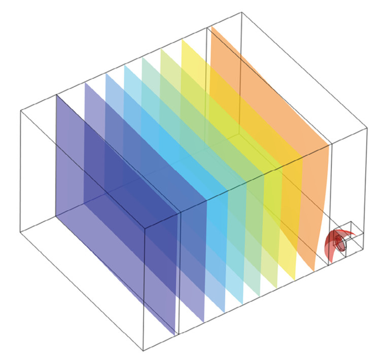
Looking at the sound pressure field via isosurfaces as in Figure 4, the sourced field looks quite close to the mode shape in Figure 1, although slightly warped toward the subwoofer. This warping is seemingly enough to throw off the symmetry that the mode has on its own, and so the resulting microphone pressures must adhere to that.
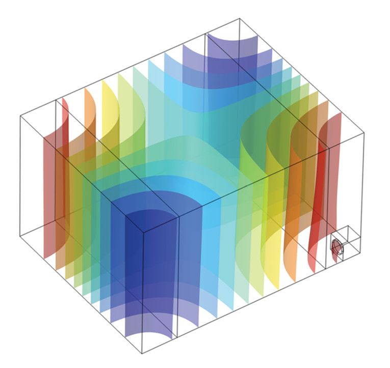
For another frequency of 55Hz, where a mode can also be found, the sourced sound field again bears a lot of resemblance to the mode shape, as shown in Figure 5, and again a clear resonance is only seen for some microphone points. With a single subwoofer in a corner being one of the simplest sourcing situations, it should be clear that while knowing the modes of a room certainly gives some insight to what a sourced output might generally be, it will typically not be possible to determine the sourced sound field directly from the modes, without any additional mathematical operations.
Another Viewpoint
Now, while the incentive may not be immediately obvious, the room could instead be viewed as a tube with its length equal to one of the room lengths. A natural axis given by the direction the main speakers are “pointing” is assumed, such that the front wall (near the main speakers) constitutes one end of the tube and the rear wall the other end of the tube. In a tube, there would be one boundary surface at one end where typically some velocity distribution is assumed, and at the other end, some impedance boundary conditions might be assumed. All other walls are assumed hard.
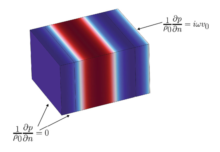
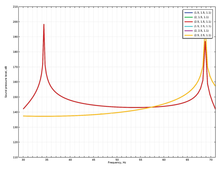
Let us first see what the sound field looks like for a constant velocity over the entire front wall with hard walls everywhere else. In this situation, only axial modes have the potential to be excited, so a planar sound field with axial standing waves will be seen, as shown in Figure 6. There is only reactive intensity in the sound field in this situation, and no propagation. The associated SPLs for the six measurement points as shown earlier are depicted in Figure 7.
It is noted how the three measurement points at one common length coordinate have the same level, since the field is constant for any cross-section, and the same goes for the other three listening positions. The peaks seen in the responses are related to the axial modes only. This points toward a way to at least get rid of some resonances.
Absorbing Boundary Condition
In the next step, we imagine a perfectly absorbing boundary condition at the rear wall without being concerned about how to achieve that. Since there is now no reflection at the end of the “tube,” there are no standing waves in the axial direction, and so there will be no modes excited. The main aspect of tube acoustics to consider for our purpose here is that “the plane wave always propagates,” meaning that in an infinite tube, the plane wave can be found to have the same magnitude at any distance, as opposed to all other possible tube modes, which will only propagate when the excitation frequency is above their individual cut-on frequencies.
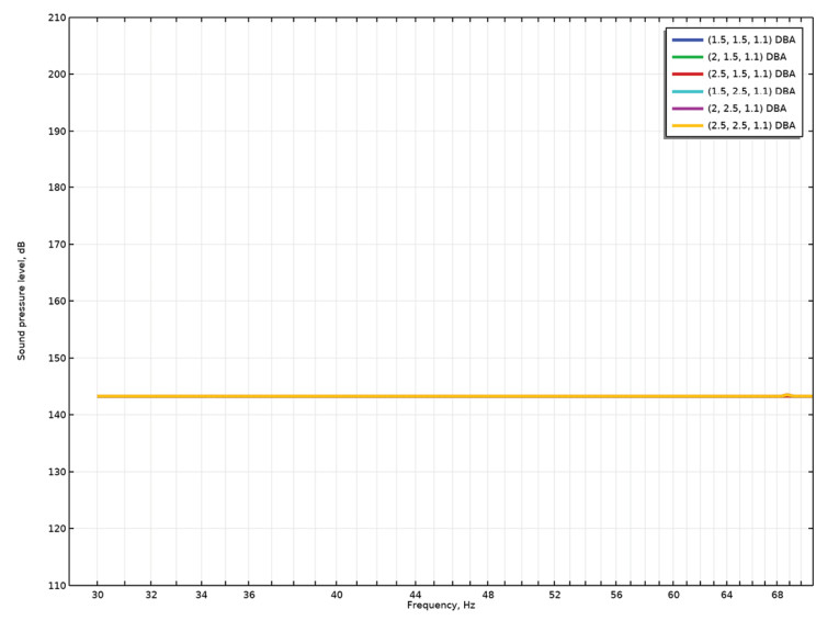
If the frequency in question is lower, such excited modes will be evanescent, so their associated pressure field is only seen near the velocity boundary condition without any propagation. Either way, since only the plane wave is excited here, the pressure field will be plane at any frequency, also above cut-on frequencies of higher order modes. The intensity of the field is purely active at any frequency, as there is only propagation and no reflection. Since the characteristic impedance of this “infinite tube” setup is a real constant, the pressure level should be flat for a constant velocity on the front wall, which is confirmed in Figure 8. A subwoofer will not deliver a constant volume velocity, but this will be addressed later. At least the modal issues in the room have been eliminated here.
Exciting the Front Wall
The next challenge is how to excite the front wall. Well, with enough subwoofers placed on the wall, this should be achievable. The subwoofers should all be the same as we are going for a constant movement. As their voltage-to-velocity transfer function will have a particular filter characteristic instead of being a constant, the pressure level will not necessarily be flat, but over a narrow frequency range, this may not be an issue.
The absorption on the rear wall seems to be more of a problem, since no passive absorber will eliminate all the reflections at low frequencies. This is dealt with by controlling the rear wall velocity. Think of it as the rear wall “getting out of the way” of the pressure field. Locally, the air particles are simply vibrating back and forth in an axial direction and so if a wall moves in the same manner as the particles, one can essentially achieve a radiation condition via a velocity boundary condition as an “active absorber.” This can be achieved by incorporating the time delay related to waves travelling from the front wall to the rear wall into the velocity of the rear wall, as illustrated in Figure 9.
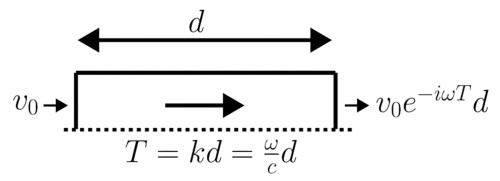
Again, we are omitting any losses in the room, so only the time delay is needed in the signal processing, but in practice it may take more signal processing due to the damping on walls and general furniture. The rear wall displacement would require some electrical energy to drive whichever transducer would be driving the wall, and here it is also assumed that this vibration can be achieved satisfactorily by a few subwoofers only. The energy associated with driving these subwoofers at the rear wall will not add to the overall sound energy in the room compared to having a perfectly absorbing boundary somehow being achieved passively, so in that sense the “active absorber” system is inefficient for the total number of subwoofers needed.
Achieving Constant Velocity Distribution
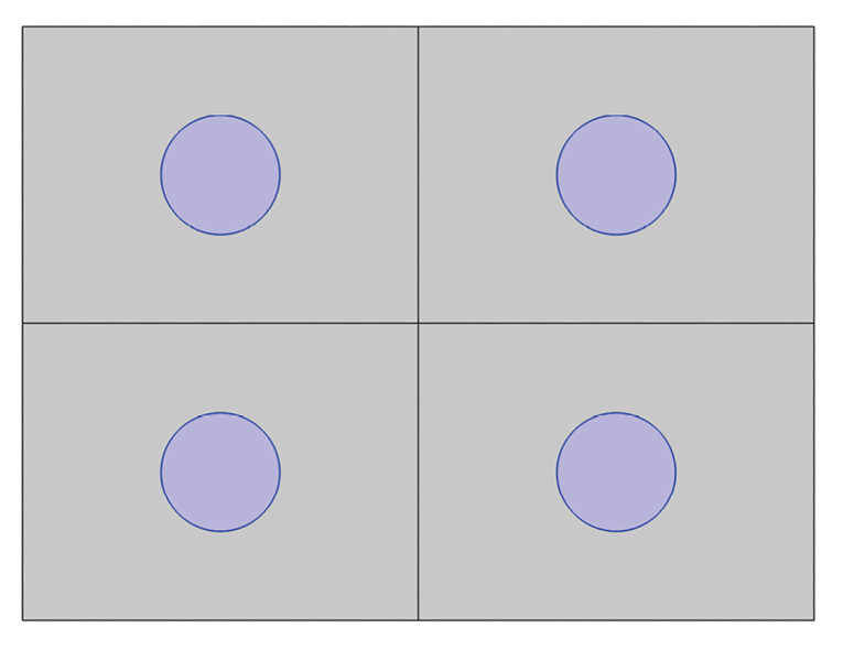
There is, however, now the question of how to achieve the constant velocity distribution over the front wall and the rear wall. The strategy in the Double Bass Array, seemingly first mentioned in an article by Anselm Goertz, Markus Wolff, and Lutz Naumann [4] is to have several subwoofers placed on the front and rear walls, in a pattern as depicted in Figure 10 for a 2×4 subwoofer layout. The point here is to have the mirror sources line up to achieve a homogenous distribution of sources ad infinitum.
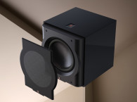
While the subwoofers don’t cover the walls, the wavelengths in question may be long enough that the strategy still works globally, although near the wall some discrepancies are expected locally. First, we assume that the subwoofers are placed in the walls such that their cones are flush with the walls, as shown in Figure 11, which would require in-wall mounting.
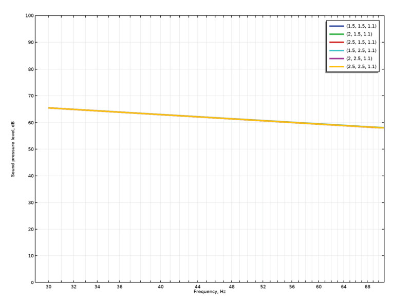
Four subwoofers at either end of the room is probably toward the maximum number that most would be willing to experiment with, and so that is what is chosen for now. The resulting SPL is shown in Figure 12 for a constant acceleration on the subwoofers. There is a slope due to not having a constant velocity, but no resonances are seen across the six measurement points, although the subwoofers do not take up the entire wall, so the principle holds even for this finite number of subwoofers.
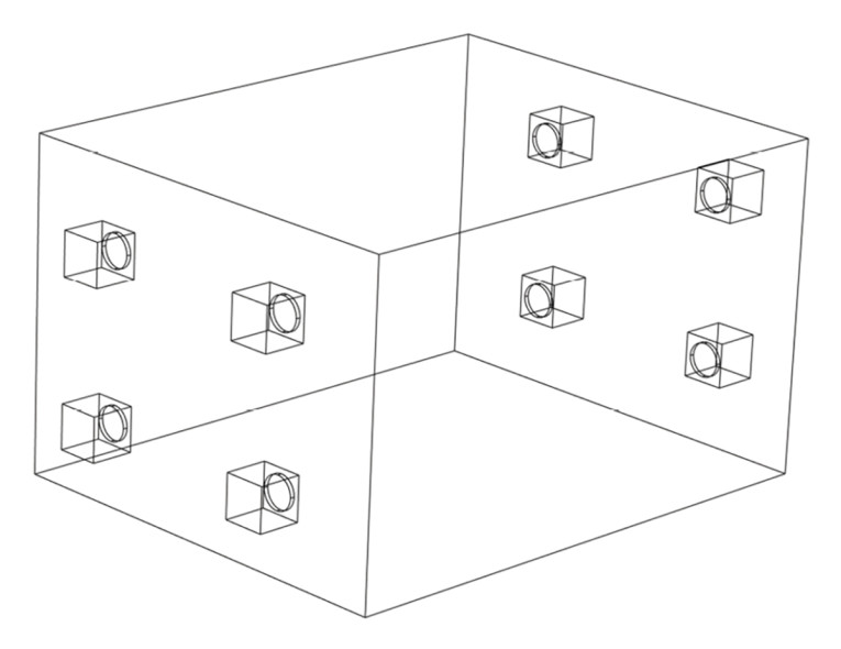
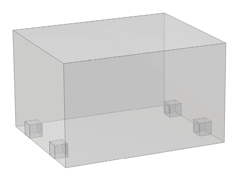
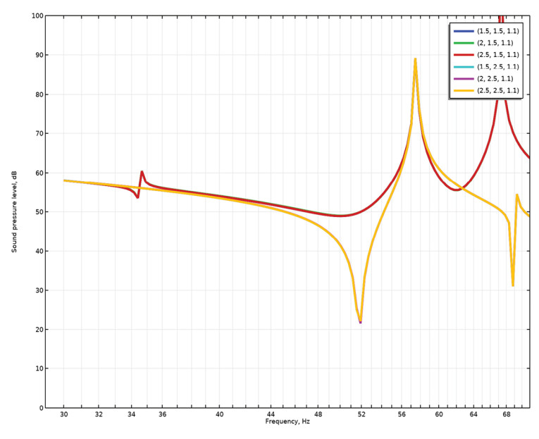
In a final step, we assume that only four subwoofers total are available and that they must be placed more realistically on the floor and in the room instead of sitting inside the walls. In this case, the required time delay is less obvious, since the sub-to-sub distance is different than the wall-to-wall distance. We assume here that distance is from front wall to rear wall. The room and subwoofer layout are shown in Figure 13 and the response in Figure 14. There now appears some resonance issues at particular frequencies, but that is to be expected for this non-ideal situation. One could now investigate what happens with fewer or more subwoofers placed differently, but some issues with the practical implementation have at least been hinted to here.
To approximate the planar sound field in a non-cuboid room, one needs to set it up as an optimization problem. This has been explored with the C.A.B.S approach [5], but this should also be set up directly in for example COMSOL Multiphysics with the Acoustics module and the Optimization ditto.
Conclusion
The Double Bass Array principle has been demonstrated to have some desirable characteristics, but it requires several subwoofers, careful placement, and likely equalization to achieve the best possible pressure response across multiple seats. These considerations are shared with all other in-room bass strategies, so if you do have multiple subwoofers, there are certainly a lot of layout schemes to investigate.
I believe that software such as REW can be used for experimenting with subwoofer layout and time delay settings, so I would encourage anyone interested in the DBA approach to start with such modeling. For a practical implementation, there will likely be a need for lots of tweaking, and of course the cost of several subwoofers and the space they take up should be considered also. aX
References
[1] R. Christensen, “Room Gain,” audioXpress, July 2023.
[2] E. Geddes, “Why Multiple Subs,” GedLee LLC, www.gedlee.com/Papers/multiple%20subs.pdf
[3] T. Welti and A. Devantier, “Low-Frequency Optimization Using Multiple Subwoofers,” Journal of the Audio Engineering Society, 54(5),
pp. 347-364, 2006.
[4] A. Goertz, M. Wolff, and L. Naumann, “Optimierung der Tieftonwiedergabe in Tonstudios und Abhörräumen” (Optimizing bass reproduction in recording studios and listening rooms), www.nubert.de/media/b3/5f/41/1662983943/optimierung-der-tieftonwiedergabe.pdf
[5] A. Celestinos, “Low frequency sound field enhancement system for rectangular rooms, using multiple loudspeakers,” Aalborg University, 2007.
This article was originally published in audioXpress, October 2024


