In the nearly 100 years of speaker innovation, occasionally we see something that makes our heads turn. And it makes us want to look closer. Dinaburg Technology has a unique approach not only to packaging a passive radiator in a small volume but also to taking advantage of a back wave from the loudspeaker’s diaphragm to optimize the passive radiator’s response and the off-axis performance of the active driver. The advantages are clearly audible, and it makes us want to take a closer look.
Concentric Passive Radiator
The passive radiator loudspeaker enclosure was described by Harry F. Olsen in his 1935 patent, and other work [1,2,3]. Over several decades, detailed analysis was carried out by Neville Thiele [4], Richard Small [5,6], by Y. Nomura and Z. Kitamura [7], Thomas L. Clarke [8], and Erich Hossach [9]. All the variants are capable of alignments that give better performance than conventional sealed-box, vented-box, or traditional passive radiator system, in that properly aligned passive radiator systems offer an improved tradeoff of low-frequency response, enclosure size, and efficiency.
Dinaburg Technology has developed a speaker design based on a concentric passive ring radiator offering the reduced excursion and other benefits of a vent substitute over a sealed back chamber, not just for bass speakers but also for midrange speakers. The passive radiator acoustically filters out the upper range of the sound energy in the back chamber minimizing comb filtering. This passive radiator takes the form of a flat ring that is compliantly held in place by surrounds on both the inner and outer periphery and provides for tighter constructive coupling to the active speaker (and to the room) compared to an open bass reflex port or a nonconcentric passive radiator, which might have to be located on a different side of the enclosure. There are several positive aspects with the ring configuration beyond the obvious benefits of a conventional vent-substitute design. The design techniques potentially enable lower distortion, extended frequency range, higher efficiency, and wider and more consistent beamwidth (dispersion), applicable in several situations.
In the home and business installation industry, in-wall and ceiling applications for loudspeakers with a wide frequency bandwidth and a smooth, monotonically decaying, acoustic power response is ideal and difficult to achieve. This is also the case in automotive cabin interiors, and other similar vehicle cabins. In the home or business location, the listener is seldom on axis, and can sometimes be in an area where the nearby boundaries are complicated.
In the case of passenger vehicles, the listener is never on-axis with any of the loudspeakers and is mostly receiving reflected sound from nearby surfaces. Having a smooth acoustic power response increases the quality of a diffuse and well-balanced sound field presented to the listener in a vehicle and in a home or business listening environment. In both environments, the depth of packaging and available footprint are always concerns. To be able to create a comparable or better low-frequency performance for a typical 6.5” diameter speaker package in an enclosed air volume that also provides a smooth axis response is unique, especially if the active loudspeaker is essentially a 3” diameter loudspeaker. This is the example upon which we will focus.
How It Works
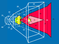
In Mikhail Dinaburg’s description of his invention (US Patent: US10812912B2), he refers to the loudspeaker cone as a diffuser [10]. The description of a loudspeaker cone as a diffuser invokes the purpose of a boundary, or a surface, to be used to better match the pressure of two air volumes. In the case of a loudspeaker, the cone diffuser is an inefficient one. Mikhail Dinaburg, in his design theory, strives to improve the efficiency of this poor diffuser. A passive ring radiator is added around a smaller diameter active loudspeaker, mounted in a box volume. This is shown in Figure 1, which is from Dinaburg Technology’s white paper “Theory of C2S: The coplanar concentric stabilizer for cohesive sound reproduction.”
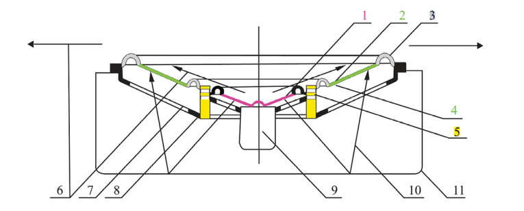
The ring radiator is considered a stabilizer for better matching the air volumes on either side of the boundary that is the active loudspeaker cone. This stabilizer is concentric with, and can be considered in the same plane of, the active part of the loudspeaker. This concentric passive ring radiator can reduce the required excursion from the active loudspeaker to produce lower frequencies similar to the benefit a bass reflex port design has over a sealed chamber.
The coplanar concentric stabilizer from the design theory, which is the concentric passive ring radiator, has a better coupling to the outside air volume than a bass reflex port would have or even a nonconcentric passive radiator, which might have to be located on a different side of the enclosure. The passive ring radiator, designated as coplanar concentric (C2S) in the design theory, can also be thought of as acoustically filtering out the upper range of the sound energy in the back chamber, minimizing comb filtering. As shown in Figure 1, the passive radiator (titled the stabilizing part) takes the form of a ring that is held in place by inner and outer surrounds of a compliant material.
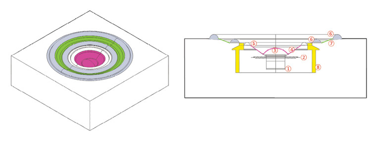
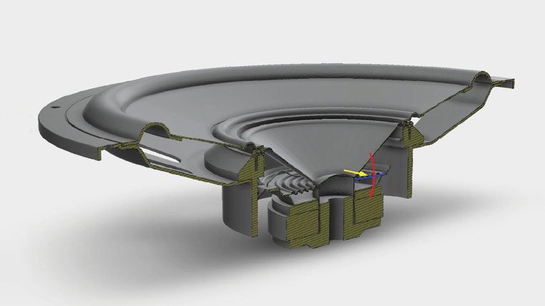
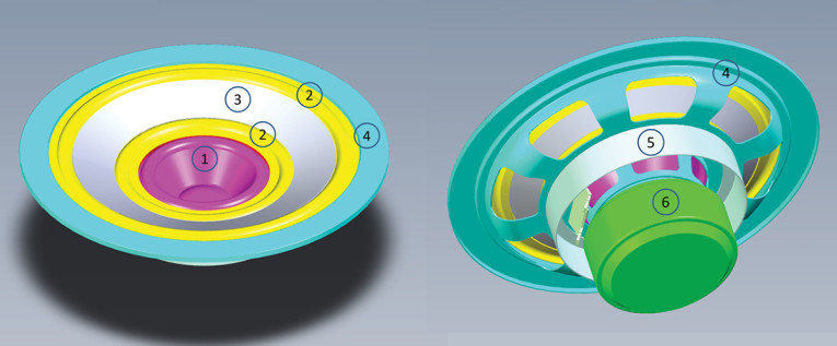
To realize the design for prototyping and for computer-aided mathematical simulation in COMSOL Multiphysics, a 3D CAD file was generated. The Simulation CAD (Figure 2) was created for the specific multiphysics approach that COMSOL [11] would provide, integrating the mechanical, acoustical, and electrical simulations. Figure 3 and Figure 4 show the CAD construction for a 90mm (3”) active loudspeaker and a 125mm (6.5”) outer diameter passive ring radiator (i.e., the coplanar concentric stabilizer). The box volume is 2.6L (65mm × 200mm × 200mm).
To build the Multiphysics model, the motor structure in the model is represented with the lumped electromagnetic parameters for the active 90mm (3”) loudspeaker, which were applied for the driving voltage level (at 1W), force factor (Bl), coil DC resistance and inductance (L), the membrane surface area (Sd), and peak driving voltage (V0).
For the remainder of the model components, materials and thicknesses were defined for paper cone material, glues, paper cone + surround, spider, air, paper dust cap, paper dust cap + cone, copper wire, NBR surrounds; and these were applied to the shell elements that defined the boundary for each of the model’s entities.
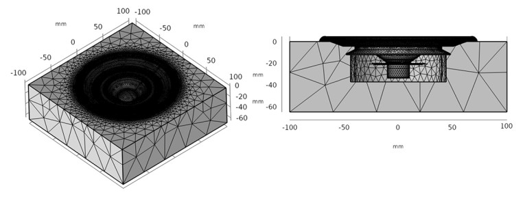
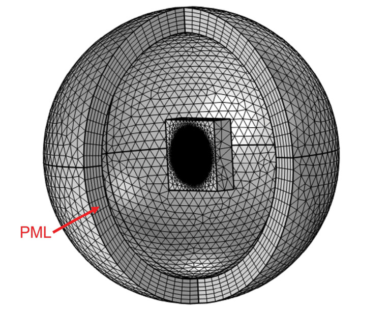
The first model was run on a full speaker and box model (Figure 5) in a 3D Acoustic Simulation (Figure 6). Perfectly Matched Layers (PML) were placed 4 meters from the center of the active speaker’s dust cap. The PML is used to create a non-reflective boundary for a Free Field Solution.
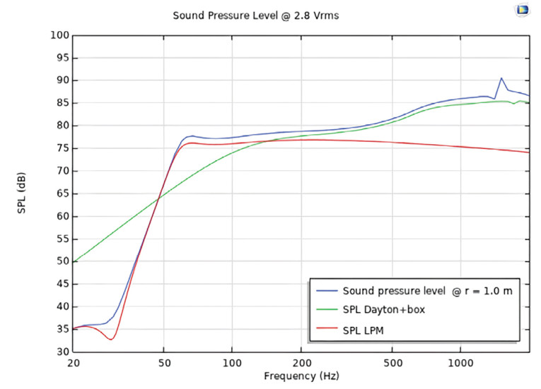
The 1/12th octave acoustic solution was able to give results for 20Hz to 2kHz. This provided enough low, mid, and high frequencies to validate the model and assess some of the salient acoustic behavior in the design concept. Figure 7 shows the low-frequency match of the COMSOL simulation of the 90mm (3”) active driver to a Linear Parameter Model (LPM) for the 2.6L box model. The basic box model was calibrated for materials below 500Hz. Above 500Hz, the effect of the box loading in the midrange can be seen.
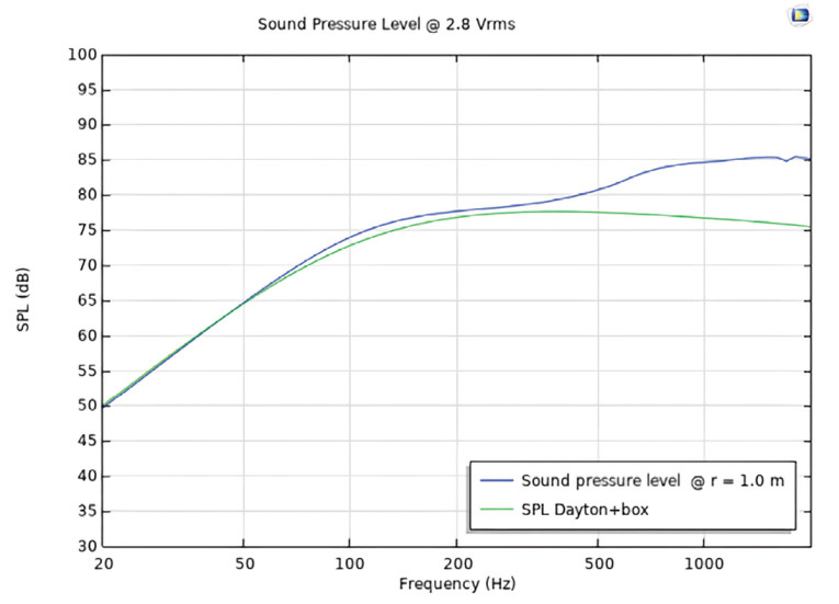
In Figure 8, we see the on-axis SPL up to 2kHz for the 3” speaker in a box simulation without the Dinaburg alignment and for the same 3” with the Dinaburg alignment, as well as an LPM estimate for a ring radiator. Here we can see the effect of adding the passive ring radiator to the box. We can also see that the low-frequency simulation agrees well with an LPM for a simple passive radiator in a box. What we don’t see in the on-axis response is the pressure behavior inside the box and how that might relate to the coherent relationship of the interior and exterior pressure and how that could relate to improved midrange clarity and improve off-axis behavior.
To review the off-axis behavior and to see a more detailed behavior of interior and exterior pressure, a model was needed that extended in high frequency up to at least the upper frequency of the active driver, which is approximately 12kHz.
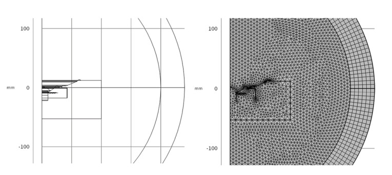
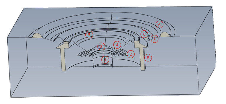
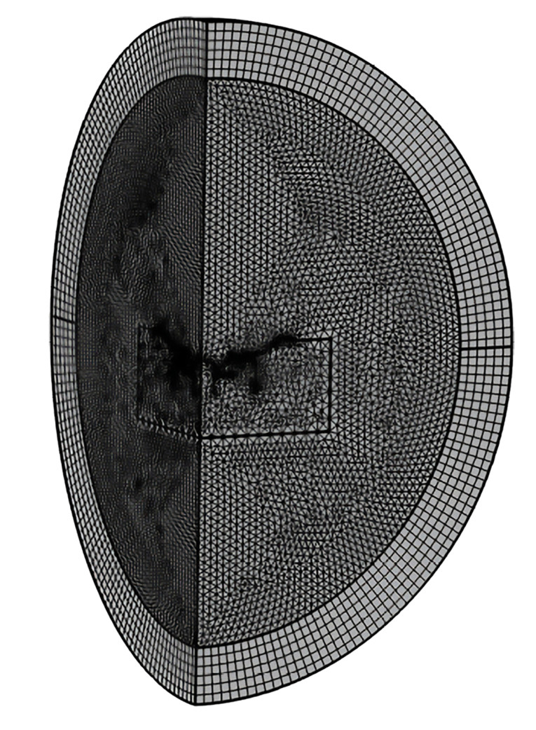
To achieve the higher frequency range in the FEA model, a smaller element size is needed. Filling the full 3D model with smaller elements would reach the limit of computer memory. To continue to use an FEA model, there are symmetries in the design that can be used to reduce the size of the model, but allow for more, and smaller, elements. Figure 9 and Figure 10 show the quarter-symmetry model that was created. This gave us the 20Hz to 12kHz frequency range in the model, which was solved at 1/12th octave frequency points.
The Proof
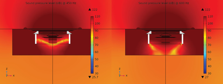
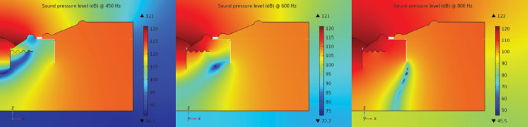
In Figure 11 and Figure 12, there is some evidence that the phase relationship between the rear radiation of the active speaker and the passive ring radiator is being controlled by the phase stabilizing ring. The pressure on the passive ring radiator is more coherent with the active speaker radiation. We can follow how well the phase is managed by following the pressure null (the lighter color pressure center line) that travels from the back of the active driver around the phase ring (shown here in white) and up to the passive ring radiator, which is characterized by Dinaburg as the C2S stabilizer (i.e., Coplanar Concentric Stabilizer).
The higher frequency model will help see not only the lower and mid voices of 500Hz to 1600Hz behavior, but also the frequencies that define the off-axis behavior.
With the quarter-symmetry model, the frequency response (Figure 13) was extended to 12kHz, which was more than adequate for the active driver’s upper bandwidth frequency.
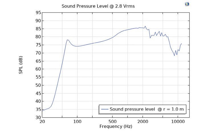
Figure 14 shows a look at the sound pressure in the box interior only for the quarter-symmetry model in a three-quarter view. We can see that the quarter-symmetry has added a more refined display of the sound pressure contours.
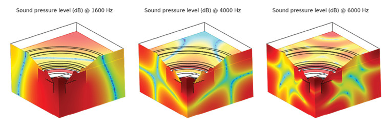
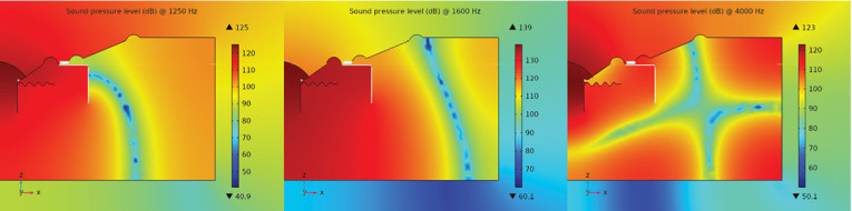
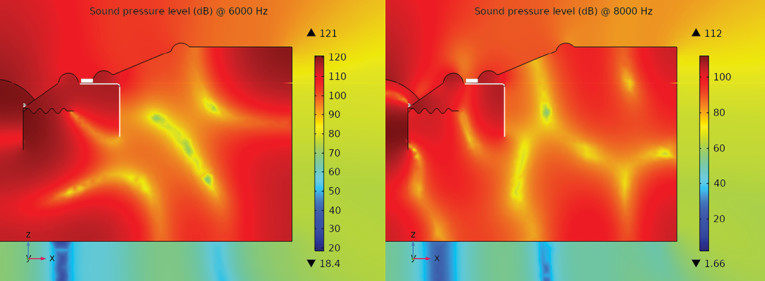
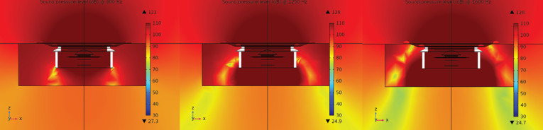
We can again see in Figures 15–17 the control of the pressure inside the box and the coherence of phase at the passive ring radiator in the model, which again is characterized by Dinaburg as the C2S stabilizer. When we look at the off-axis polar plots, for higher frequencies of 6000Hz and 8000Hz, we see a broader off-axis response — less beaming. It is much closer to the low-frequency off-axis response, even at angles up to 60° off-axis (Figure 18).
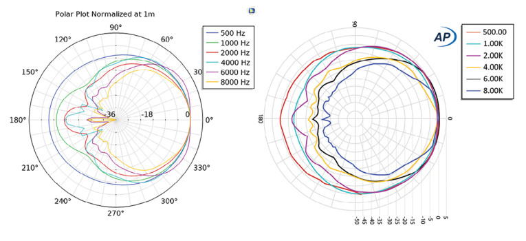
The polar response measurements of the prototype’s directivity compare well to the simulation results. This encourages us to use this simple COMSOL model as a method to analyze the Dinaburg design concept. The measurements of a prototype can also help understand more about the Dinaburg design’s behavior to correlate to the listening quality of the prototypes and the COMSOL model results.
Measurements
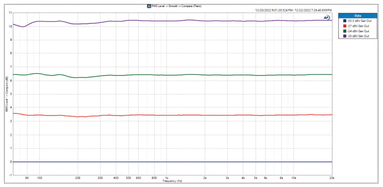
From measurement data of a physically realized prototype (measurements performed by Dan Foley of Do No Harm Music, dan.foley@donoharmmusic.com), a very low level of midrange power compression and a drop in midrange distortion was seen in the Dinaburg speaker (Figure 19 and Figure 20). The drive level to the speaker was increased from 30mV (-30.5dBV) to 100mV (-20dBV) in approximately 3dB steps. The total change in level from start to finish was 10.5dB. From 100Hz to 20kHz, there was minimal compression.
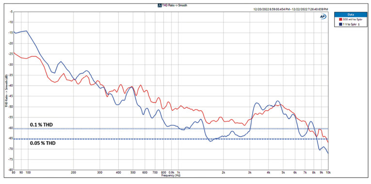
Despite a 10dB increase in SPL, the THD in the midrange (500Hz to 3kHz) went down by as much as 10dB with THD levels as low as -65dB (0.05%).
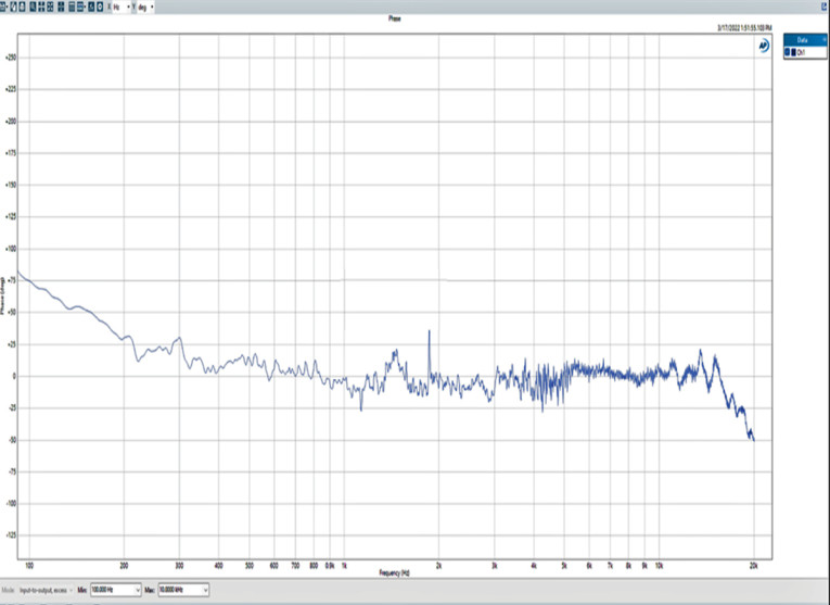
In Figure 21, phase was measured for the prototype (by Jim Tuomy, jimtuomy@gmail.com). This graph could also help anticipate the intelligibility and clarity of the Dinaburg design. A phase measurement made across what could be called the “crossover” frequency of a passive radiator or bass reflex system, will generally have a very sharp transition going from the active radiator to the passive radiator. In this case, the transition area is in the 200Hz region. There is a lack of discontinuity in the 200Hz region, which is surprising. This could be at least partially responsible for the Dinaburg C2S system’s good performance when playing complex multi-voice harmony.
In several listening tests, there is general agreement that reproduction of the midrange, in particular with female vocals, sounded clearer when reproduced by a Dinaburg C2S driver compared to an equivalent conventional driver.
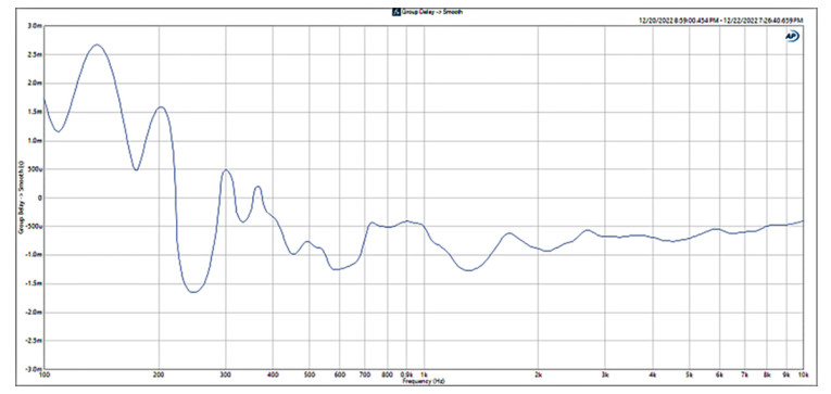
One of the unique aspects of a driver designed following the Dinaburg C2S design theory is that it can reproduce a wide range of frequencies from one acoustic center. As such, the group delay would be very smooth and at a constant delay over a wide frequency range.
That would mean that from low frequencies typically reproduced by a woofer to frequencies reproduced by a tweeter, the group delay would vary slightly. The measurements show that from 400Hz to 10kHz, the group delay is ±250 microseconds, which is indeed very slight and smooth (Figure 22).
Conclusions
In the early empirical days of designing and tuning automotive audio systems, hours and days were spent finding the right combination of tuning parameters for a specific speaker placement in the cabin interior to create not only a good tonal balance, but sense of staging and spaciousness.
At first, it wasn’t clear why one simple architecture would sound more coherent and spatial than another, until time was spent analyzing each one of the aspects of the car’s interior, speaker design, and speaker location to understand the timing relationship within the car’s interior modal behavior and reflective surfaces near a speaker and a listener. Then, the understanding of why a solution worked could be applied to a variety of applications for automotive interiors. This analogy applies to the Dinaburg Technology’s design theory to understand how it can be consistently applied across many product designs and applications.
The early prototypes that were created had the attributes from listening tests of intelligibility and clarity, and a depth of detail in the harmony of vocals. They maintained these attributes even when listening at a wide off-axis angle of 60°.
Each aspect of the Dinaburg C2S design was analyzed, either through physical measurements of prototypes built from designs optimized with FEA models or from the detailed look at acoustic pressure behavior on the interior of the enclosure and on the interior and exterior surfaces of the passive ring radiator, which was only practical with the FEA models, using the tools of COMSOL Multiphysics. We could see the effects of the phase stabilizing ring interacting with the concentric ring radiator (i.e., designated by Dinaburg as the coplanar concentric stabilizer, as previously mentioned).
The phase stabilizing ring seems to enable the passive ring radiator to present a very stable phase relationship to the listener on and off-axis. Virtual listening tests, using auralization to play back music convolved with the design’s simulated impulse response agreed with the listening experience of practical prototypes.
Indeed, complex multi-voice harmonies were clear and cohesive, without audible distortion. The COMSOL modeling and the measurements so far justify that. It makes sense that Dinaburg calls this design concept “C2S, The Concentric Coplanar Stabilizer.” We now have an understanding of the nature of the solution and how it can be applied to a variety of applications: From automotive speakers, in-wall and ceiling speakers, and even headphone designs. aX
References
www.dinaburgtech.com
[1] H. F. Olson, “Loud Speaker and Method of Propagating Sound,” U.S. Patent 1,988,250 application, February 17, 1934; patented January 15, 1935.
[2] H.F. Olson, “Drone-Cone, Phase Inverter,” Journal of the Audio Engineering Society, Volume 21, No. 7, pp. 582–583, September 1973.
[3] H. F. Olson, J. Preston, and E. G. May, “Recent Developments in Direct-Radiator High-Fidelity Loudspeakers,” Journal of the Audio Engineering Society, Volume 2, No. 4, p. 219, October 1954.
[4] A.N. Thiele, “Loudspeakers in Vented Boxes, Part I and Part II,” Journal of the Audio Engineering Society, Volume 19, No. 5, pp. 382, May 1971;
No. 6, p. 471, June 1971.
[5] R. H. Small, “Direct Radiator Loudspeaker System Analysis,” Journal of the Acoustical Society, Volume 20, No. 5, pp. 383, 1972.
[6] R. H. Small, “Passive-Radiator Loudspeaker Systems, Part 1, Analysis,” Journal of the Audio Engineering Society, Volume 22, pp. 592-601,
October 1974.
[7] Y. Nomura and Z. Kitamura, “An Analysis of Design Conditions for a Phase-Inverter Speaker System with a Drone Cone,” IEEE Transactions on Audio and Electroacoustics, Volume AU-21, pp. 397-407, October 1973.
[8] T. L. Clarke, “Augmented Passive Radiator Loudspeaker,” U.S. Patent 4,076,097, application August 4, 1976; patented February 28, 1978.
[9] E. Hossbach, “Loud Speaker System,” U.S. Patent 3,772,466, application November 24, 1971; patented November 13, 1973.
[10] M. Dinaburg, “Speaker with Dual Diffuser,” Dinaburg, United States Patent No. 10,812,912 B2, 2020.
[11] COMSOL Multiphysics 5.5., Model Library, COMSOL AB, © 1998-2021.
This article was originally published in audioXpress, September 2023.