It is (I hope) well-known by now that electrolytic capacitors generate nonlinear distortion when they are used with a significant signal voltage across them. Just recently this issue resurfaced when designing a tone-control stage that was to be Return-To-Flat (RTF) i.e., the tone control had a reduced effect, falling to none, below 10Hz. Making this happen with non-electrolytic capacitors was not practicable due to the large value (22uF) required. I therefore made a closer examination of the subject of electrolytic distortion. I quote from my tone-control article [1] published in audioXpress and now available online here.
"THD was measured at full boost and 10 Vrms out, just short of clipping, and with C2 as a 22/63V part there was. 0.0008% at 20Hz; without the capacitor you get 0.0006% With a 22/35V part you find a rather less appealing 0.0023%."
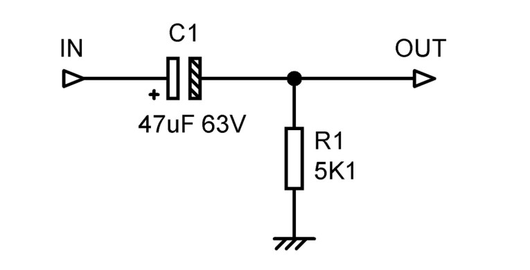
I hope you agree that 0.0008% at 20Hz is acceptable compared with 0.0023%; it appears that the voltage rating of the electrolytic was very important. This was a little unsettling, as I have said elsewhere this is not the case. Still, in this application, at its given impedance, it clearly was an important factor and so I decided to dig deeper. Electrolytics of varying size and voltage were tested driving a resistive load (Figure 1), with input signals of 3, 5, 7, and 10 Vrms, which I think you agree is fairly severe. 10 Vrms is about the biggest signal you will get out of an op-amp, and the maximum output of my Audio Precision machine at 10Hz.
The standard rated temperature for electrolytic capacitors is 85ºC, though the lifetime at that temperature is only 2000 hours, and they are of course operated at much lower temperatures in practice. Recently, capacitors rated at 105ºC have become popular as they show better reliability. It was expected that the 105ºC parts would show lower distortion, on the rather nebulous grounds that they were of superior construction.
The sample capacitors measured were all standard polarized types from reputable manufacturers, all about 10 years old, and all had been stored in suitably cool and dry conditions. Unfortunately, none of the values were available in different temperature ratings. Bear in mind that electrolytics typically have a tolerance of ±20% on their value, which can affect the results slightly. Up to five samples of each type were measured.
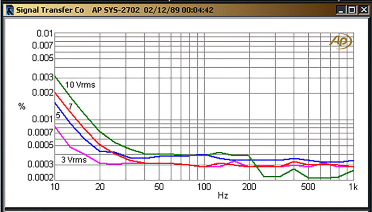
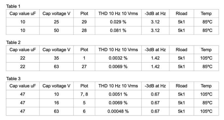
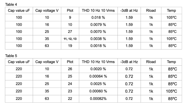
Looking at the results in the Tables below, some trends are clear. (The "Plot" column is a reference to my measurements, these are not shown here except for the curves in Figure 2). In general a higher rated voltage means less distortion; for example see Table 3 where 47/63 has less than a tenth of the distortion of 47/10. Similarly, in Table 4, 100/63 has a tenth of the distortion of 100/10. Things are less orderly in Table 5; 220/16 has less than a third of the distortion of 220/10, but 220/25 has more, and 220/63 gives more distortion than 220/35. Tables 1 and 2 show a backward relationship where the higher voltage part gives more distortion; this may be something to do with the lower capacitance values, but this is currently uncertain.
As regards the effect of rated temperatures, in Table 3 we would expect 47/16 to give less distortion than 47/10, but in fact it gives more.
This sort of testing is of course a fairly brutal way to treat electrolytic capacitors, and it is likely that their reliability under normal use would be impaired. It is wise to discard the experimental samples so they do not get built into important equipment.
In conclusion, while the results are not as clear-cut as one might hope, there is a general result that if you are troubled by electrolytic capacitor distortion, you should use the highest voltage part you can. The results for the temperature rating are much less obvious, but nowadays I always use 105ºC parts for greater reliability (less drying out and reduction in value) over time. In the future I plan to test some non-polarized (NP) electrolytics; one might hope the results would be better.
I hope you’ve found this helpful. aX
References
1] Douglas Self, Optimizing Variable-Frequency Tone Controls, audioXpress, December 2023
This article was originally published in The Audio Voice newsletter, (#452), January 11, 2024.