In the design considered here, in each band the frequency at which control begins is variable over a 16 to 1 range, making it much more useful for correcting speaker deficiencies or room anomalies. Very few manufacturers have offered this. The only examples that come to mind are the Yamaha preamps; the C6 (1980-81), the C70 (1982-83), the C80 (1984), and the C85 (1986-88)—all of which had low and high frequencies variable over wide ranges (they could overlap in the middle) and Q controls for each band as well, as the tone controls were of the peaking rather than shelving kind, rather like the parametric EQ in a mixing console. These preamps today change hands for startling sums of money.
In 1996 I published a design for what is commonly known as the Precision Preamplifier in Electronics World [1], and one of its main features was a treble/bass tone control with the frequencies variable over a 10:1 range. When I mentioned on the DIYaudio board in May 2012 [2] that I had developed an improved version of this tone-control, I was surprised at the enthusiasm for its immediate publication. It duly appeared in Jan Didden’s Linear Audio Volume 5 [3].
The tone-control was quite sophisticated; apart from variable frequencies, it also gave Return-To-Flat (RTF: also known as Return To Zero decibel) operation. The responses are caused to revert back to unity gain outside the audio band. Strenuous efforts were made to ensure that the response was not affected by variations in pot track resistance, which are usually ±20%. This used a lot of op-amp sections (six in each channel of the tone control stage) and it seemed to me that if we compromised a little on pot-track dependency, two much simpler stages dealing with bass and treble separately, and borrowed from mixing console technology with only two op-amp sections per stage, might work pretty well. The price of freedom from pot-track dependency is not eternal vigilance but more op-amps. As a tone-control it can be added to existing preamps that are not so blessed, to give great flexibility. Be aware a low-impedance drive is required if the equalizer’s response is to be predictable.
Optimizing a High-Frequency Equalizer
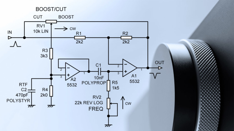
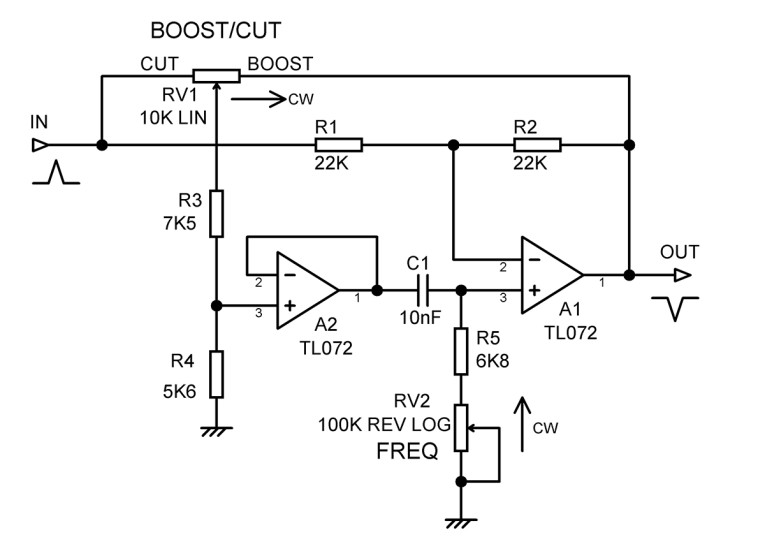
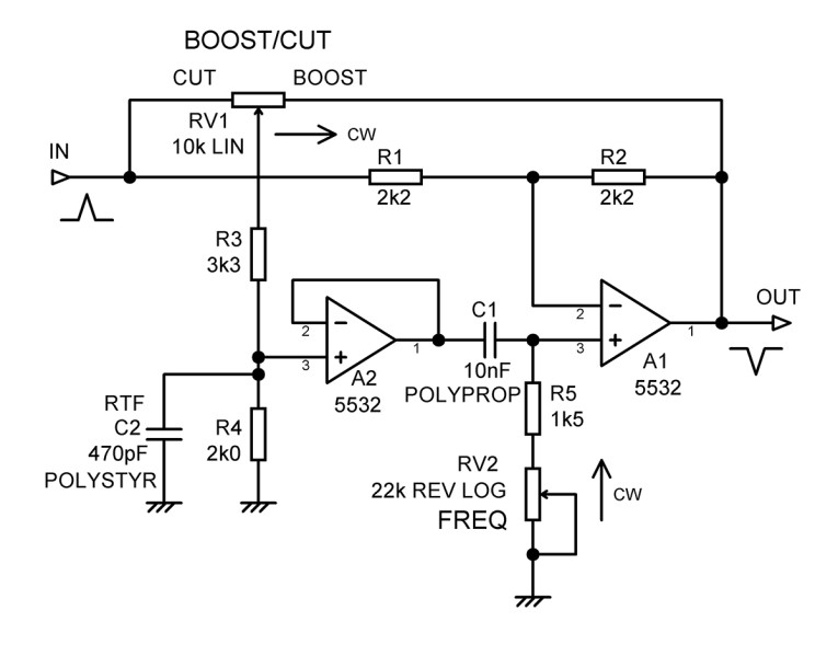
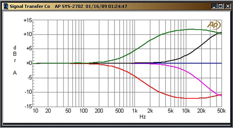
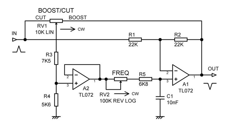
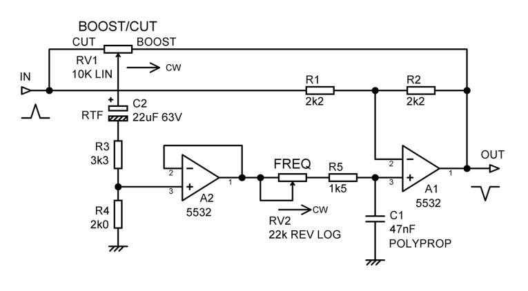
A typical variable frequency high-frequency shelving equalizer is shown in Figure 1. R1 and R2 set the basic gain to -1 and ensure that there is DC feedback to fix the operating conditions. When the wiper of RV1 is at the output end, positive feedback partially cancels the negative feedback through R2 and the gain increases. When the wiper of RV1 is at the input end, the signal fed through the frequency-sensitive sidechain R3, R4, A2, etc., causes partial cancellation of the input signal, so gain is reduced. The signal from pot RV1 is scaled by divider R3, R4, which set maximum cut/boost. This signal is buffered by voltage-follower A2 and fed to a high-pass RC network comprising C1 and (R5 + RV2). Only high frequencies are passed, so the equalizer has no effect at low frequency.
Specifying the frequencies at which equalizers work is difficult. One possibility is stating the frequency at which the response is 3dB less than the shelving level for maximum boost, but this is useless for any other boost/cut setting. In the past I have used the frequency at which the response is 1dB more or less than the flat response, calling it the break frequency. The downside is that the break frequency is some ways from where the main action happens.
This EQ section was and is pretty much the industry standard in mixing consoles that did not aspire to parametric EQs, and I certainly do not claim to have originated it. It gives a lot of flexibility with a minimum of components. Because of its mixer ancestry I tend to think of it as an equalizer rather than a tone-control, but I have used the terms interchangeably here.
Originally, both op-amps would have been TL072 sections, for the powerful reason that they were the cheapest reasonable op-amps available. Another more subtle reason is that as a JFET-input part, the input bias currents were very low, and they could be connected directly to a pot wiper without crackling noises when the control was moved. This saved a lot of money on DC-blocking capacitors. Crackling pots on a mixer are bad because you may move the control for dynamic effects, but I suggest there is rather less of an issue in a hi-fi preamp, so I have here chosen to concentrate on noise.
The use of the well outmoded TL072 means the stage is noisy by modern standards. You could update the stage by using a more modern JFET-input op-amp such as the OPA2143, but in a world where supply chains are still a mess I decided to focus on the cheapest and most easily obtainable op-amp: the 5532. This is of course a BJT-input part, which gives low noise with low source impedances, and has good load-driving abilities, allowing us to use Low Impedance Design, which reduces both resistor Johnson noise and the effect of op-amp current noise flowing in the resistors. Voltage noise is unaffected. The 5532 does not have negligible input bias currents.
The focus of this article is on the optimization of the stage by reducing its noise, and this means doing more thinking rather than spending more money on fancy parts. All noise measurements are 22Hz to 22kHz RMS-sensing, unweighted.
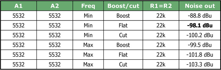
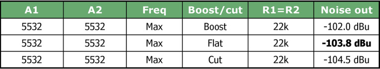
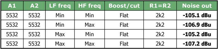
Noise calculations are wonderful things, but they get rather complicated in circuits like this with a mixture of positive and negative feedback. It is much quicker to build the circuit and measure it, so I did. There are many settings possible, but I only tested the extremes of boost/cut and frequency, as otherwise we’d be here all week. See the results in Table 1.
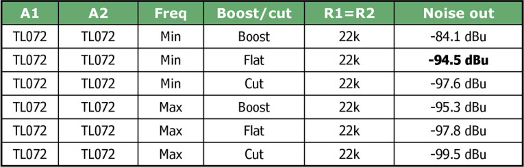
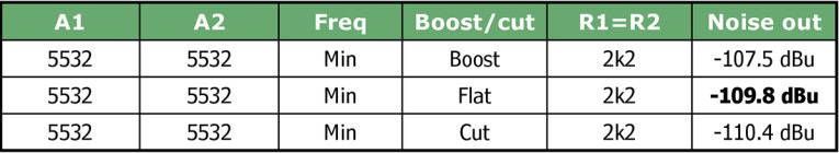
Step 1: Obviously the first thing to do is replace the TL072 with a 5532 section, and Table 2 shows an immediate improvement of 2dB to 4dB at the various settings.
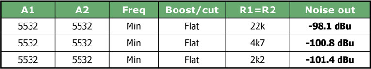
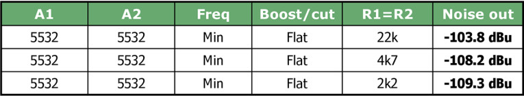
Step 2: I suggest the next thing to look at is the relatively high value of R1 and R2. Using a 5532 means we can reduce these considerably. From here on in, to reduce the amount of measuring, we are looking at just minimum frequency (which gives the biggest variation in noise with boost and cut, because the amount of the audio spectrum affected is larger) and settings of maximum boost, flat, and maximum cut. The results for the flat condition are bolded in the tables. We get a very handy 3.3dB reduction in noise at zero cost, as in Table 3.
Step 3: The stage in Figure 1 gives ±15dB of boost/cut, which is standard for mixing consoles. It is however a bit excessive for hi-fi use, so the range was reduced to ±12dB by reducing R4 to 4k7. That affects the noise, so it is re-measured in Table 4.
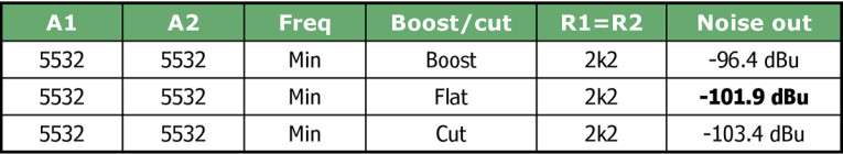
If you compare Table 4 with the top three rows of Table 2, we have reduced the noise by from 2dB to 7dB, depending on the boost/flat/cut setting.
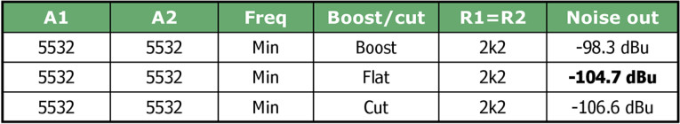
Step 4: Now what? Could R3 and R4 be reduced in value, keeping their ratio the same so that the maximum boost/cut is unaltered? Back in the day, the conventional wisdom was that R3 and R4 could not be much lower than shown in Figure 1, because the loading effect on the boost/cut pot would cramp the control to the middle of the pot rotation. I did not then question it. However, now I do question it, because recent simulations showed that reducing R3 to 3k3, and R4 to 2k0 (less than half the original values) only modified the intermediate response curves by 1.4 dB or less. But how much will it reduce noise? See Table 5. Comparing Table 5 with Table 4, we have reduced the noise by 2dB at minimum. We move on and see what else we can tamper with.
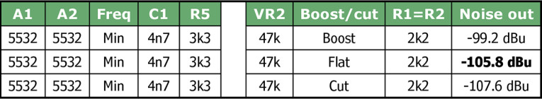
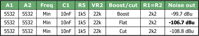
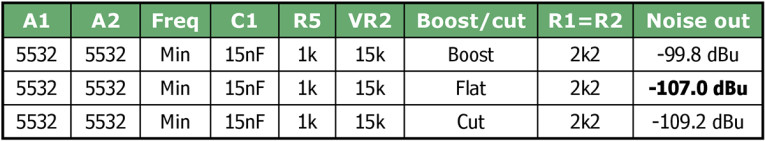
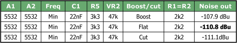
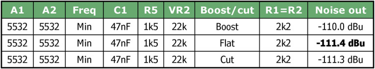
Step 5: Reducing the impedance of the frequency selective network C1, R5, VR2 looks promising; obviously both resistors and the capacitor need to be scaled to keep the frequency response the same. In Table 6 we halve the impedance, gaining about 1dB, and in Table 7 we halve it again, gaining another 0.8dB. Table 8 takes it about as far as it can be pushed, due to the loading effect of R5 on A2 at minimum frequency, and the further noise reduction is only some 0.3 dB. Given that 15kΩ pots are not going to be easy to find, Table 7 looks like the best result. The optimized circuit is shown in Figure 2. Capacitor C1 should be polystyrene or polypropylene to avoid distortion. Just by changing component values and op-amps, the noise set flat at minimum frequency (worst case) is reduced from -94.5dBu to -107dBu, an improvement of no less than 12.5dB without extra cost.
The only component not tampered with so far is the boost/cut pot RV1. Reducing its effective value to 5kΩ and then 3kΩ gave improvements of only a fraction of a decibel and introduced concerns about the load placed on the op-amp and the previous stage. The pot was therefore left at 10kΩ.
Another feature provided by the Linear Audio preamp was the RTF outside the audio band. To implement this, we need to stop the tone control action at very high frequencies, and the simplest way of doing that is to put a small capacitor across R4. The result of adding a 470pF capacitor across R4 is demonstrated in Figure 3. The capacitor should be polystyrene to avoid distortion.
The typical tone-cancel switch is a changeover that gives a brief break in the audio as it moves between tone-control and bypass. I hold that the resulting transients make critical judgements harder, and a no-break switch that just turns on and off the tone-control action is superior. No-break high-frequency EQ cancel can be implemented by a short to ground at either the non-inverting input to A2 or the non-inverting input to A1. The latter is preferred as the noise from A2 does not reach A1 in cancel mode.
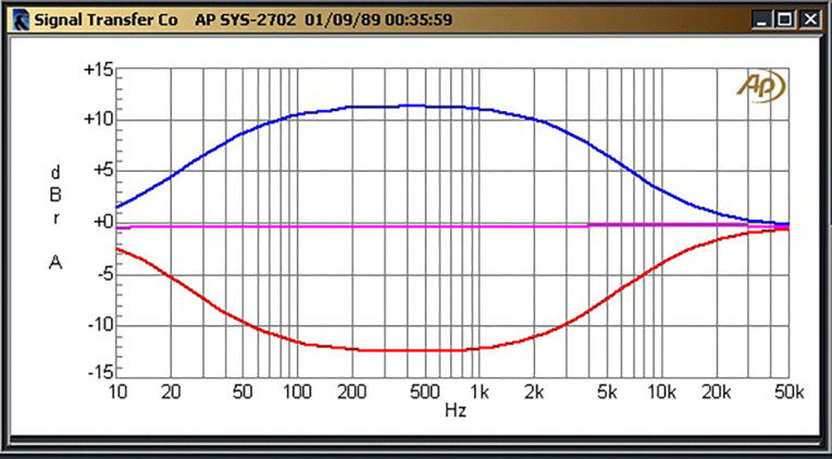
The final re-designed stage is shown in Figure 2, and the response at the frequency extremes is shown in Figure 3. The lower frequency curve shows the start of RTF action at 20kHz. When the equalizer is set to flat with a 3Vrms input, THD remains at 0.0004% from 20kHz down to 10Hz.
The equalizer stage inherently phase-inverts so it needs another inversion before or after it to maintain absolute phase. An extra stage that merely inverts to correct phase has never appeared to me a good use of power and components; here the obvious answer is to cascade it with the equivalent low-frequency equalizer, which also phase-inverts, giving a conventional two-band tone control, and getting the phase straight again.
Optimizing a Low-Frequency Equalizer
The low-frequency shelving equalizer works in the same way as the high-frequency equalizer but uses a low-pass rather than a high-pass sidechain. The classic circuit is shown in Figure 4. The noise output of the stage set to maximum frequency (the worst case) is shown in Table 9. The noise out with the equalizer set flat and to maximum frequency is -99.7dBu, compared with -94.5dBu for the high-frequency version. This is because the frequency-selective side chain in the low-frequency equalizer is a low-pass network and so attenuates the noise from R3, R4, and A2. In Tables 9-14 the noise in the flat condition is bolded.

The optimization of the low-frequency equalizer proceeds exactly as for the high-frequency equalizer.
Step 1: First replace the TL072 with a 5532 section, and Table 10 shows the noise reduced by 4.1 to 4.6 dB in the three boost/cut settings.
Step 2: The relatively high values of R1 and R2.are reduced in stages to 2k2, as shown in Table 11.
Step 3 and Step 4 are then carried out together to save time, so the boost /cut range is reduced from ±15dB to ±12dB, and R3 is reduced to 3k3 and R4 reduced to 2k0, giving us 1.6dB less noise in the flat condition. See Table 12.
Step 5: Reducing the impedance of the frequency selective network C1, R5, RV2 by making R5 = 3k3, C1 = 22nF gives us a further noise reduction of 1dB. See Table 13. Making R5 = 1k5, C1 = 47nF gives us a yet further noise reduction of 0.6dB, and clearly, we are into diminishing returns, and we will stop there, as we did for the high-frequency equalizer. Noise has been reduced by 11.7dB for no added cost, compared with the 12.5dB for the high-frequency equalizer stage. See Table 14. Capacitor C1 should be polystyrene or polypropylene to avoid distortion.
As for the high-frequency equalizer, the only component not altered is the boost/cut pot RV1. Reducing it to 5kΩ and then 3kΩ again gave only tiny reductions in noise, and there is concern about increasing the load seen by the op-amp and the previous stage. This pot was also left at 10kΩ.
To implement the RTF function, a high-pass time-constant must be added to the sidechain so its output falls at very low frequencies. This can be simply done by inserting a capacitor C2 in series with R3, but the snag is that it needs to be large because of the relatively low value of R3 and R4; about 22µF. This would be unacceptably big and expensive if it was a non-electrolytic type. I explored using, say, a 470nF capacitor and increasing its effective value by electronic trickery, but the simplicity of the basic circuit is lost and there were some awkward problems with offset voltages. Using an electrolytic capacitor for C2 seems at first ill-advised because of the distortion it would generate if there was a significant signal voltage across it. We might piously hope there are no big signals around 1Hz, which is where this component does its work. Electrolytics also have large tolerances, but are, I think, acceptable here because small variations in response at 1Hz are of little consequence.
THD was measured at full boost and 10Vrms out, just short of clipping, and with C2 as a 22V/63V part there was 0.0008% at 20Hz; without the capacitor you get 0.0006%. With a 22V/35V part you find a rather less appealing 0.0023%. This is an interesting example of how the voltage rating of an electrolytic can affect how much distortion it creates. In other tests at differing impedances, I have found the voltage rating made very little difference. If you think that is just too much distortion, then C2 can be increased to 47V/63V, which gives about 0.0004% at 20Hz; the RTF will now take place at a lower frequency. Above 100Hz, THD level is about 0.0004% up to 20kHz. See Figure 5 for the final optimized circuit. When the equalizer is set to flat, THD remains at 0.0004% from 20kHz down to 10Hz.
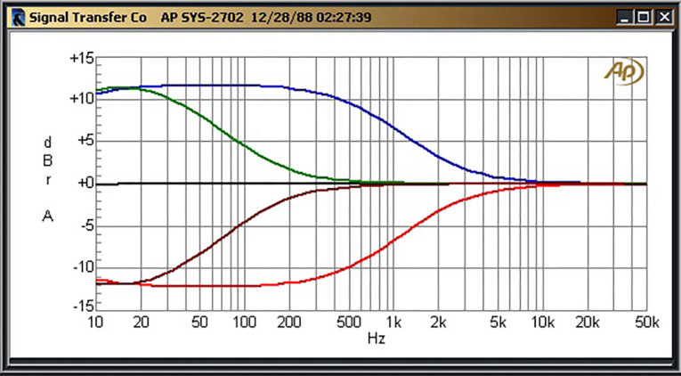
The RTF for the low-frequency equalizer does its stuff almost entirely below 10Hz, and so cannot be explored with your typical audio test gear. Function generators commonly go down to 1Hz at least, but accurate measurement is hard. My solution is to divide the values of all the capacitors by 10 times so tests can be made at 10 times the frequency. Figure 6 shows the RTF response with frequency set to maximum. This gives an accurate scaled frequency response but will not give reliable results for noise or distortion. The frequency responses for the tone control extremes (with the capacitors scaled back up again) are shown in Figure 7.
No-break low-frequency EQ cancel can be implemented by a short to ground at either the non-inverting input to A2 or the non-inverting input to A1. The latter is preferred as it stops the noise from A2 reaching A1 in cancel mode. Since there are separate high-frequency and low-frequency equalizers in each channel, an overall tone-cancel switch would have four sections, making it a bit unwieldy. I think it would be far preferable to have separate switches for high-frequency and low-frequency tone-cancel. This is also useful as corrections made at one frequency extreme are likely to have little in common with corrections at the other extreme.
When the low-frequency and high-frequency equalizers are cascaded, the noise adds in the usual RMS fashion. Table 15 gives the output noise for the flat setting at the frequency extremes of the two stages. It does not matter in which order the low-frequency and high-frequency equalizers are connected.
Conclusion
I think this article shows that our noise-reduction project has been successful. We now have a very flexible and very quiet tone-control. The break frequency ranges can be changed to suit requirements, without changing anything else, by altering the capacitor C1 in the sidechain for both high-frequency and low-frequency cases. The break frequency ranges can be reduced if required by increasing the frequency-endstop resistor R5. Do not reduce it as this may lead to excess loading on A2. aX
References
[1] D. Self, “Precision Preamplifier 96,” Electronics World, July/August and September 1996.
[2] DIYaudio bulletin board,
www.diyaudio.com/forums/solid-state/209004-new-doug-self-pre-amp-design-22.html
[3] D. Self, “A Low Noise Preamplifier with Variable-Frequency Tone Controls,”
Linear Audio, Volume 5, p. 141.
This article was originally published in audioXpress, December 2023