In Part 2 of this article, I followed the same test protocol that I used in Part 1. This means that for testing I used shunt feedback with noise gain of three for five different loads; no-load (NL) and 3kΩ, 2kΩ, 1kΩ, and 500Ω loads. This tests for basic op-amp distortion in favorable circumstances. I also used series feedback with a noise gain of three for five different loads, as before. This adds some common-mode voltage, so distortion is usually worse.
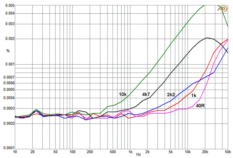
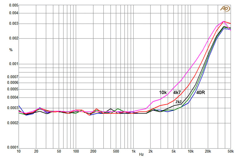
Then I used a voltage follower for five different loads — maximum feedback but also maximum common-mode voltage. Then the voltage follower with no load for five different source resistances; Rs = 40Ω, 1kΩ, 2.2kΩ, 4.7kΩ, and 10kΩ. This is a more severe test for common-mode distortion and gives much higher total harmonic distortion (THD) readings; it must be remembered, however, that the test is done at 9Vrms, close to the maximum possible level, and much greater than a nominal signal level of say 2Vrms. If the extra distortion is mostly second harmonic, which is usually the case, the reading will be reduced by a factor of 4.5 times at this lower end.
Testing Begins
Figure 22 shows the four test circuits, and it is identical to Figure 1 used for the Part 1 measurements, more details about the circuit can be found there (audioXpress, January 2025). Measurements were made with an Audio Precision SYS-2702. Note that in the first two tests (Shunt and Series feedback configuration) the noise gain (which is also the distortion gain) is kept constant, although the input-output gains are different. R1 and R2 are the same value in every test.
As in Part 1, all tests were done with ±15V rails. In each case supply decoupling was simply 100nF between the V+ and V- supply pins, next to the op-amp; no instability was encountered. In this article, low frequency is below 1kHz and high frequency is above 1kHz. The lowest THD measurable, being limited by noise, was 0.0002% to 0.0003% depending on the test used. More information about the significance of specific distortion mechanisms can be found in my book, Audio Power Amplifier Design.
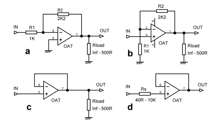
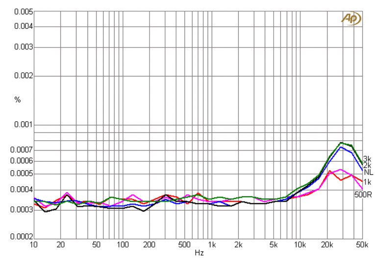
With shunt feedback around an LM4562 as in Figure 23, THD at high frequency (above 2kHz) is definitely better than the 5532 for the lighter loads but is only slightly better with a 500Ω load. Unlike the 5532, THD below 2kHz is unaffected by load.
With series feedback as shown in Figure 24, the distortion on light loads is much better than for the 5532, and also better than the shunt case, which is unusual and presumably points to some cancellation of two distortion mechanisms.
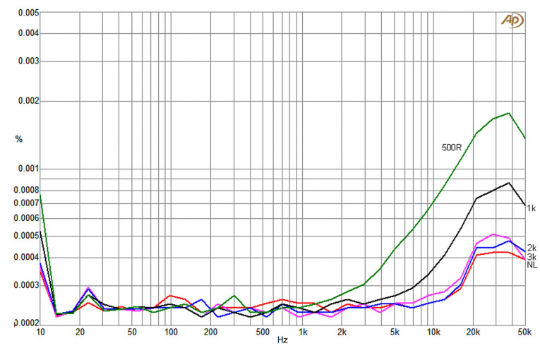
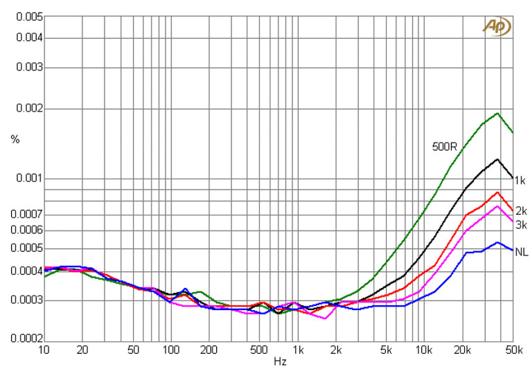
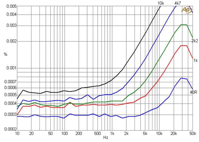
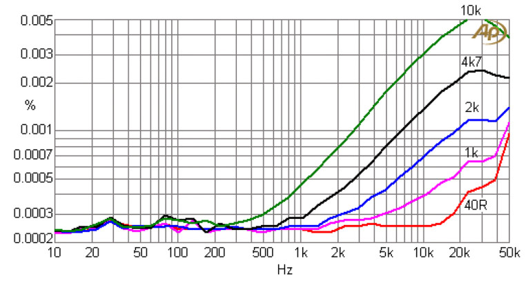
Figure 25 shows the distortion from the LM4562 as a voltage-follower with various loads. Distortion is notably lower due to the increased negative feedback factor. Distortion at high frequency is much less than that of the 5532 and not far from the limits of measurement. Figure 26 shows the LM4562 working as a voltage-follower with no output load, but with an added source resistance Rs in series with the non-inverting input. Distortion is lower than the 5532 for low Rs, but significantly worse for 2.2kΩ and up.
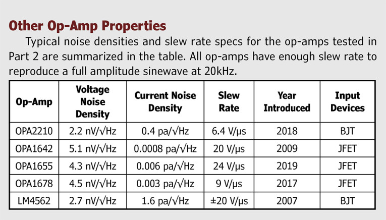
The OPA2210 op-amp. The OPA2210 is a BJT-input device by Texas Instruments (TI). It was introduced in 2018. It is not specially aimed at audio usage, the datasheet making no mention of it. It is only available in SMT. The maximum supply voltage is ±18V, the short-circuit output capability is a hefty ±65mA.
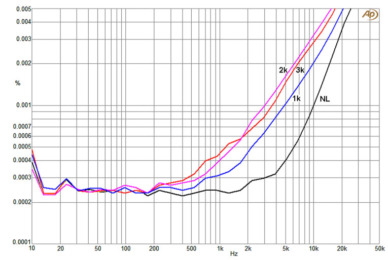
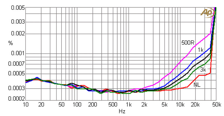
Figure 27 shows the distortion performance of the OPA2210 in shunt-feedback mode. THD above 1kHz is about twice that of the 5532 tested in Part 1 of this article. This is not encouraging. Figure 28 shows the distortion performance of the OPA2210 in series-feedback mode. THD is slightly higher than in shunt mode and again about twice that of the 5532 in series mode. Not helpful.
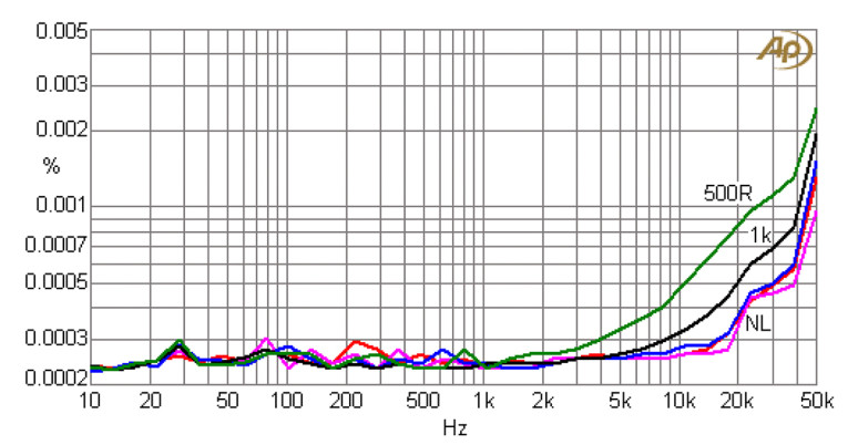
In Figure 29 the distortion for the voltage-follower connection is much reduced compared with series mode; most of the plots are on top of each other. THD is essentially unmeasurable below 10kHz; in this it handsomely beats a 5532 voltage-follower. Figure 30 shows the distortion performance of an OPA2210 voltage-follower with no output load but with various resistances inserted in series with the non-inverting input. For low values of Rs the OPA2210 is more linear than the 5532, but at 4.7kΩ and above there is little difference.
JFET-Input Op-Amps
We now move on to modern op-amps with JFET input devices.
The OPA1642 op-amp. The OPA1642 from TI is part of its SoundPlus range. It is only available in SMT. Its maximum recommended supply voltage is ±18V. It was unable to drive 9Vrms into 500Ω in shunt and series feedback modes without clipping. More on that later.
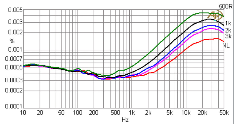
The datasheet for the OPA1642 includes the statement that special measures have been taken to reduce the effect of input capacitance that varies with common-mode voltage; this can cause considerable extra distortion when the op-amp is driven from a significant source impedance. The distortion for shunt feedback is shown in Figure 31. It is somewhat higher than for the 5532 at all loads. The 500Ω load test was not feasible as noted.
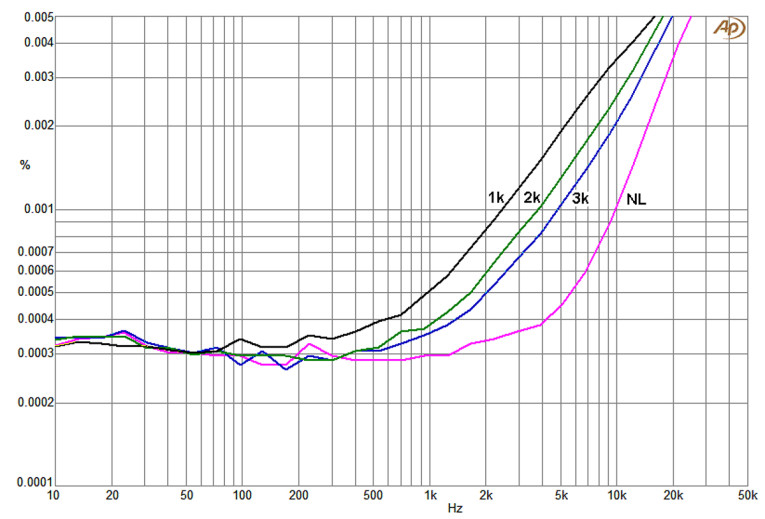
Figure 32 shows that distortion with series feedback is only slightly worse than for the shunt case. Unusually, the THD with a 1kΩ load is lower than for 2kΩ and 3kΩ, presumably due to cancellation. Distortion is worse than the 5532 for significant loading, but slightly better on light loading.
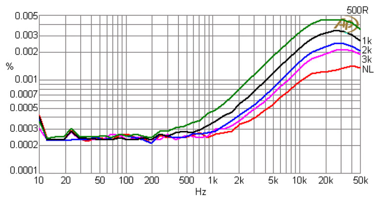
In Figure 33 the voltage follower was (just) able to drive 9Vrms into 500Ω, because it was not driving a feedback network as well as the load; the feedback networks place an extra load on the op-amp output of 2.2kΩ in the shunt case and 3.2kΩ in the series case. The distortion for loads lighter than 500Ω is lower than 5532 up to 10kHz but there is not much difference at 20kHz.
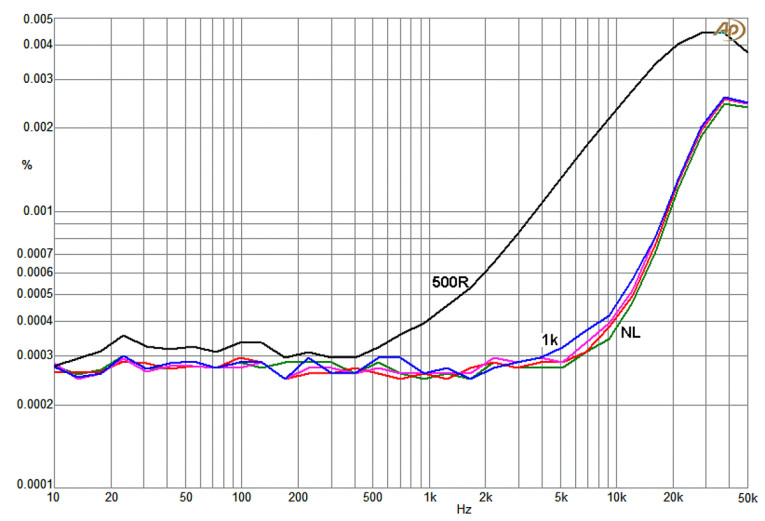
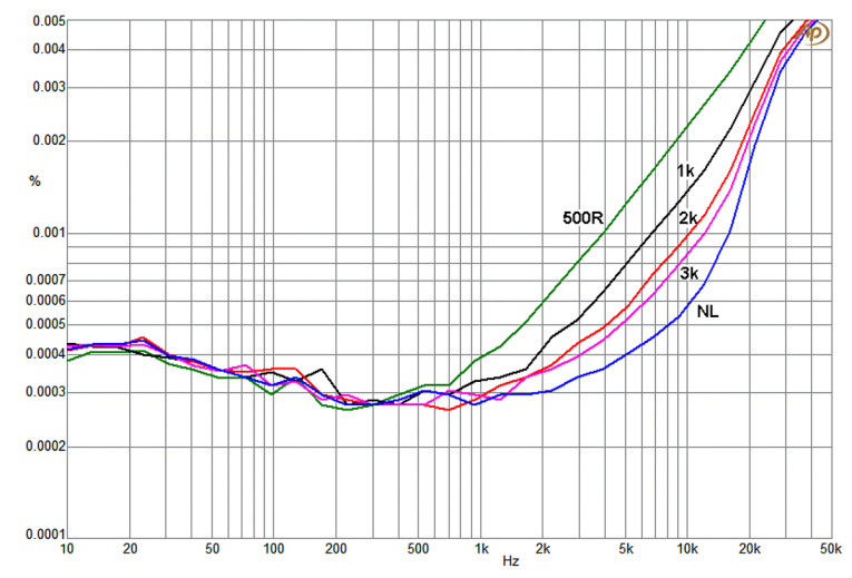
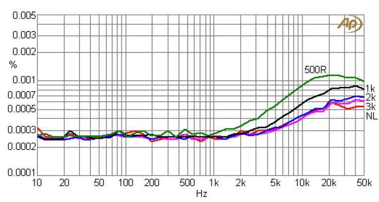
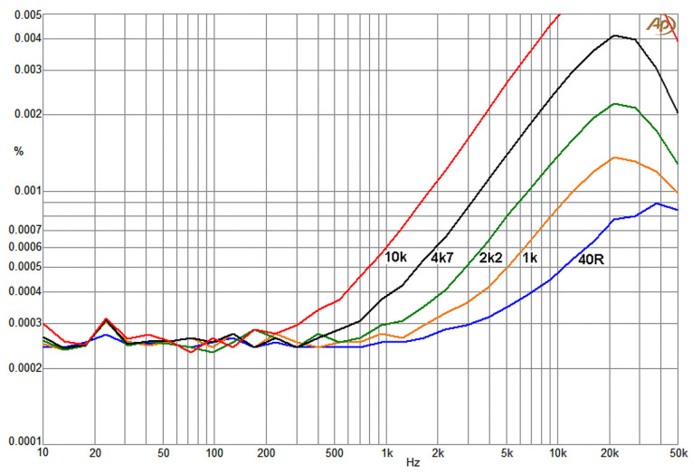
Figure 34 demonstrates that whatever TI has done to make the input capacitance constant with common-mode voltage seems to work. The common-mode distortion is much lower than for the other JFET-input op-amps tested, (OPA1655 and OPA1678) and significantly lower than for the BJT-input op-amps in both parts of this article. The datasheet gives no clue as to how it was achieved. Distortion with added Rs is about a third of that for the 5532, though this is a doubtful comparison as the common-mode distortion mechanism in a BJT op-amp is different. If you have to deal with big common-mode signals and high source resistance, this looks like the op-amp for the job.
The OPA1655 op-amp. The OPA1655 from TI is a recent JFET-input single op-amp introduced in 2019. It was tested rather than the dual version (OPA1656) because it was available. It is only available in SMT. The datasheet says that it is “...designed specifically for audio and industrial applications, where maintaining signal fidelity is crucial.”
Figure 35 shows the distortion in the shunt feedback mode. High-frequency THD is slightly lower than the 5532. Unlike the 5532 there is no increase in THD at low frequency with the 1kΩ and 500Ω loads.
The results for series feedback are in Figure 36. Oddly, the shunt mode shows higher distortion than the shunt mode. Distortion at both low frequency and high frequency are lower than for the 5532 in series mode.
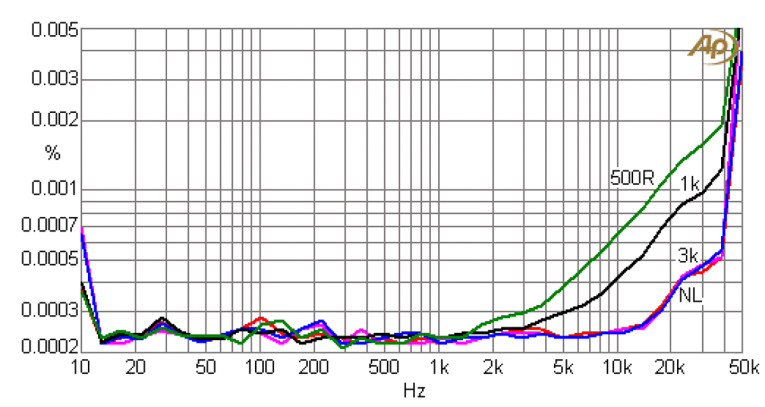
Figure 37 shows that voltage-follower THD is slightly lower than for shunt or series mode, due to the increased negative feedback. Distortion at high frequency is lower than for the 5532.
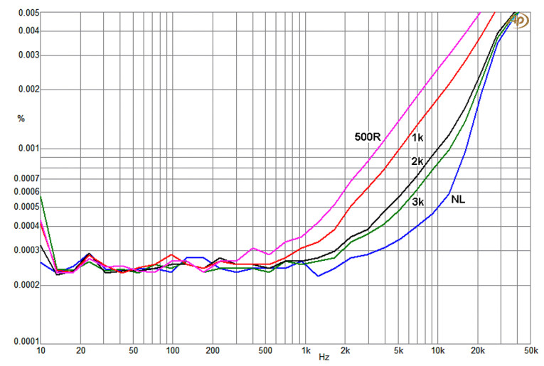
Adding a source resistance Rs (Figure 38) to the voltage-follower gives a good deal more distortion. For Rs of 2kΩ or less the OPA1655 is definitely superior to the 5532.
The OPA1678 op-amp. The OPA1678 from TI is a recent JFET-input single op-amp introduced in 2017. The OPA1678 is unusual among op-amps because it shows classic crossover distortion as given by an under-biased BJT audio power amplifier. It claims low distortion that “improves audio signal fidelity,” which indicates it is specially aimed at audio usage.
Figure 39 shows much more distortion than the 5532, due to the crossover distortion. Interestingly, Figure 40 shows lower distortion at low frequency in series mode rather than shunt mode, a similar result to that for the OPA1655. The 5532 is worse at low frequency but better at high frequency.
The voltage-follower results in Figure 41 shows distortion reduced by a factor of about three, which corresponds to the increase in negative feedback in this mode. This is probably a result of the obvious crossover distortion; other op-amps do not show this tidy relationship. Distortion at high frequency is lower than for the 5532.
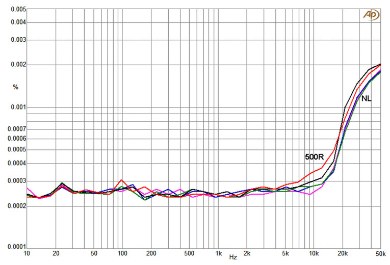
Adding a source resistance Rs as in Figure 42 has greatly increased the total distortion, which is already high. For Rs = 2.2kΩ or less the 5532 is more linear.
Conclusions Based on These Tests
The OPA2210 has more distortion than the NE5532 with shunt and series feedback, but less as a voltage-follower. It is generally beaten by the NE5532. The LM4562 is definitely better than the NE5532 with light output loading, but the common mode distortion is generally worse.
The OPA1642 cannot drive 500Ω loads in normal circumstances. But its low distortion with significant Rs stands out above all other op-amps tested.
The OPA1655 has distortion generally lower than the NE5532. The OPA1678 has crossover distortion and is not a good choice.
Overall Conclusion
While some of the newer op-amps can offer lower distortion in some configurations, the veteran NE5532 holds up surprisingly well, considering it has been around since 1979 — that’s almost four decades. aX
Read Part 1 of this article — click here
Resources
D. Self, Audio Power Amplifier Design, 6th edition, Focal Press, 2013, pp. 142-150
This article was originally published in audioXpress, February 2025