I usually use the old dependable NE5532 or the much newer LM4562 in my designs, and now and then FET-input types such as TL072 or OPA2134 when a DC servo is needed. There are many new devices that have appeared over the last years, some of them specifically aimed at audio applications, and I thought it was high time to evaluate some and see what I was missing. I will often compare newer op-amps to the NE5532 as this has been a sort of standard for decades. Some newer devices are only available in surface-mount technology (SMT), which is not very user-friendly; so I had a good friend (whose hand-eye co-ordination is far better than mine) mount them on 8-pin DIL carriers, which plug straight into a prototype board.
This article focuses on distortion as it is often not much specified, whereas for noise I have always found that using the spec figures allows pretty accurate calculations. Four distortion tests were done on each type, with an output of 9Vrms, which is close to the maximum possible. I measured shunt feedback with noise gain of three for five different loads; no-load (NL) and 3kΩ, 2kΩ, 1kΩ, and 500Ω loads. I was testing for basic op-amp distortion under favorable circumstances. Next, I measured them in series feedback configuration with noise gain of three for five different loads as before. The goal is to add some common-mode voltage; distortion is usually worse. Then it’s on to voltage followers for five different loads as before.
I wanted to test with maximum feedback but also maximum common-mode voltage. Last, I measured them in voltage follower mode with no load for five different source resistances; Rs = 40Ω, 1kΩ, 2.2kΩ, 4.7kΩ, and 10kΩ. The goal is to provide a more severe test for common-mode distortion, because while an amplifier may have a perfectly linear output, that does not mean the input currents it draws are also linear—in general they are not, and with significant source resistance this introduces a new distortion mechanism, which can be very troublesome. For more details see my book Audio Power Amplifier Design.
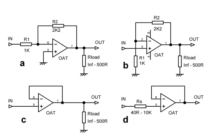
Figure 1 shows the simple test circuits used; OAT = Op-amp on Test. Measurements were made with an Audio Precision SYS-2702. Be aware that the Y-scale of the plots varies to show as much detail as possible. Note that the noise gain (which is also the distortion gain) is kept constant for the shunt and series configurations, although the input-output gains are different. R1 and R2 are the same value in every test.
BJT-Input Op-Amps
The 5532 op-amp. The 5532 has been around for decades and needs little introduction. It is often the cheapest dual op-amp around because of its extensive use in the reconstruction filters of CD players. (As an aside, the single version, the 5534, is apparently going obsolete, which is a low blow as its noise characteristics match MM phono inputs very well.) The first section of this article therefore gives the results of tests on a 5532 (not Texas) as a reference so you can compare performance.
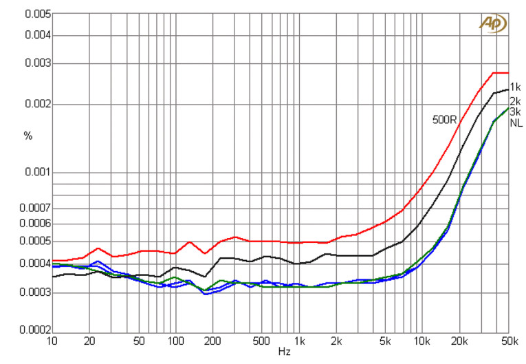
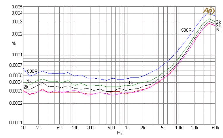
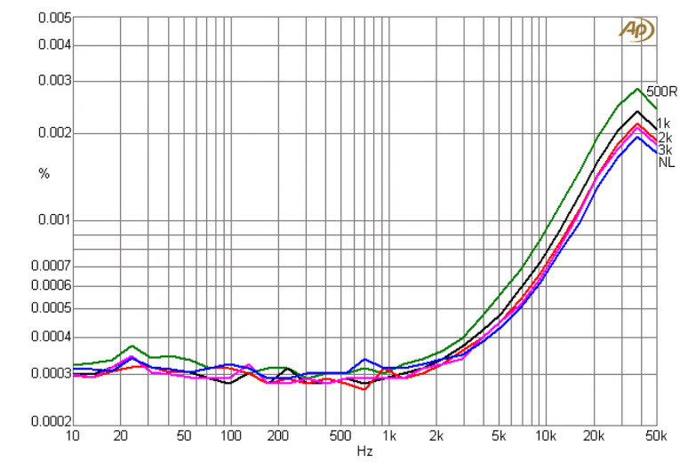
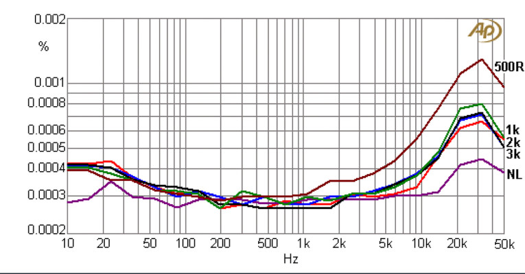
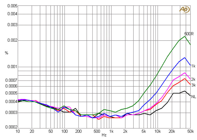
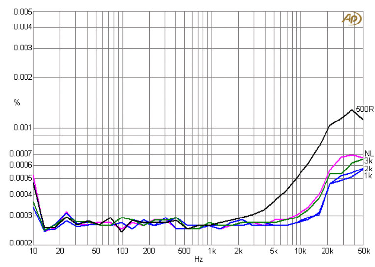
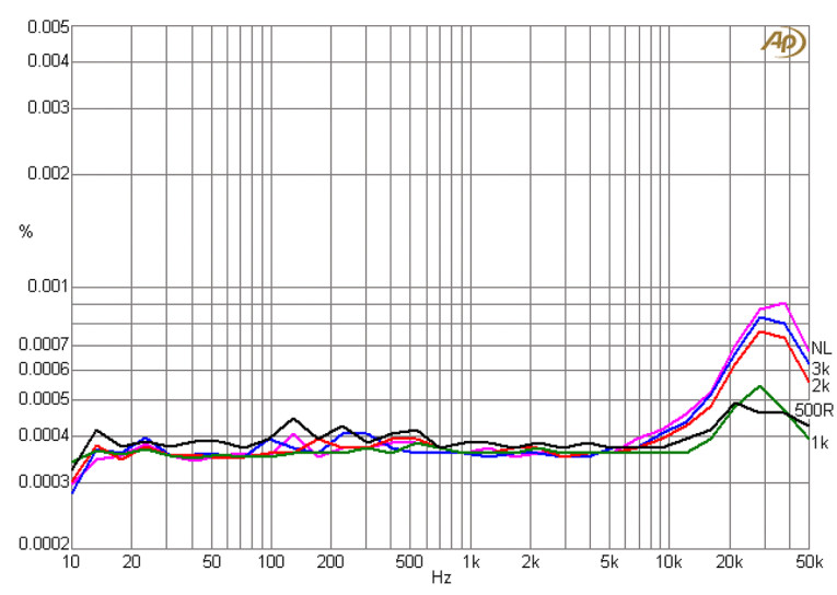
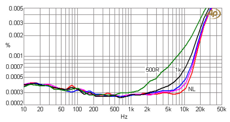
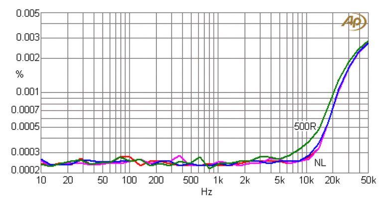
Figure 2 shows the basic 5532 distortion with no common-mode voltages to cause trouble. The 5532 is good at driving a heavy load and distortion only increases when load resistance falls below 2kΩ. The noise floor with no total harmonic distortion (THD) is at about 0.00023%. Figure 3 adds a common-mode voltage of about 3Vrms on the inputs. There is a modest increase in THD at both low frequency and high frequency. Figure 4 shows that the voltage-follower configuration gives less distortion at low frequency due to the increased negative feedback; there is still significant distortion above 2kHz.
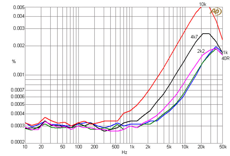
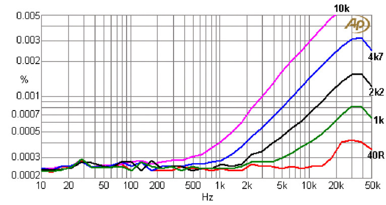
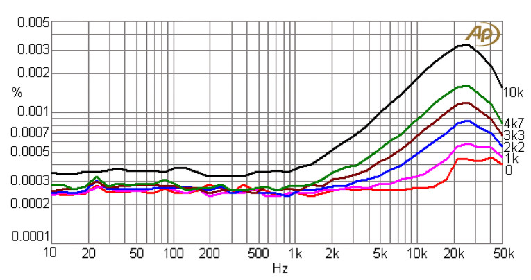
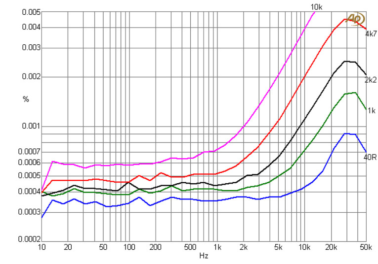
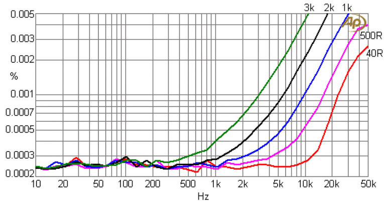
In Figure 5 there is now no load on the voltage-follower, but source resistance is inserted into the input lead. Distortion increases because while the output of the op-amp is very linear this does not apply to the currents drawn by the inputs (only the non-inverting input is relevant in this case). THD increases rapidly as the source resistance exceeds 1kΩ. The same effect occurs in discrete audio power amplifiers as discussed in my book. This is something to ponder when you are driving a voltage follower from a volume control, which shows maximum source resistance when the wiper is at the -6dB position.
The OPA1602 op-amp. The OPA1602 from Texas Instruments (TI) is a BJT-input dual op-amp introduced in 2011 with audio applications in mind; it is described as part of TI’s SoundPlus range. It is only available in SMT. Its maximum recommended supply voltage is ±18V, but the tests were done with ±15 V rails, as noted above. The output drive capability is ±30mA.
The distortion performance is shown in Figure 6, working with shunt feedback at 9Vrms output. Note the change in the Y-scale so 0.002% is the maximum. Compared with a 5532, midband distortion is lower, even with the 500Ω load, and the THD at 20kHz with a 500Ω load is halved. Better than a 5532.
The series-feedback distortion is shown in Figure 7. There is clearly some common-mode distortion as the THD above 2kHz is noticeably increased compared with the shunt feedback case in Figure 6. It is still better than the 5532 in Figure 3.
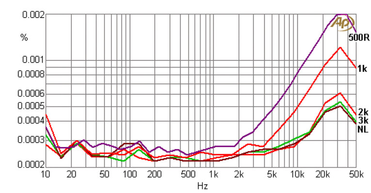
Figure 8 demonstrates the OPA1602 working as a voltage-follower with the usual output loads. The 100% negative feedback brings the distortion down, so it is barely measurable below 20kHz even with a heavy 500Ω load. The increased distortion above 20kHz is a measurement artefact. Much better than the 5532!
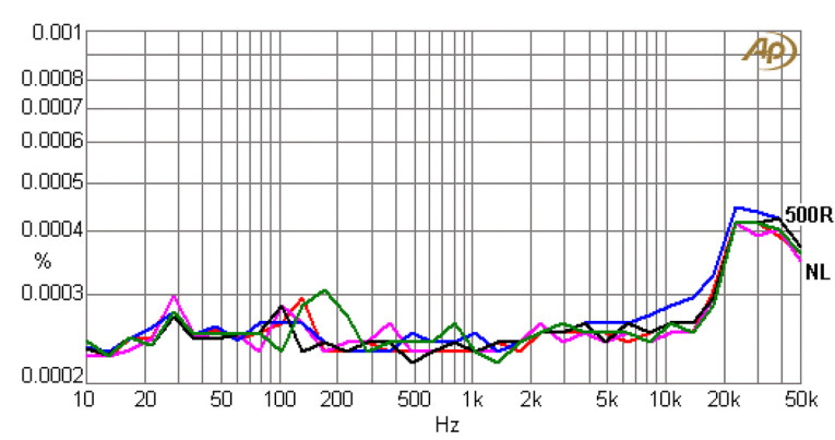
Figure 9 demonstrates the OPA1602 working as a voltage-follower with no output load, but with a resistor Rs placed in series with the non-inverting input. Distortion is markedly increased, even with Rs as low as 1kΩ, and with Rs=10kΩ, it’s pretty bad, and comparable with the 5532 results in Figure 5. Be warned.
The OPA1612 op-amp. The OPA1612 from TI is a BJT-input dual op-amp introduced in 2011; it is described as part of their SoundPlus range, aimed at audio applications. It is only available in SMT. Maximum supply voltage is again ±18V.
The distortion performance of the OPA1612 is shown in Figure 10, using shunt feedback. Note the Y-scale change. There is much less distortion than for the 5532 shown in Figure 5.
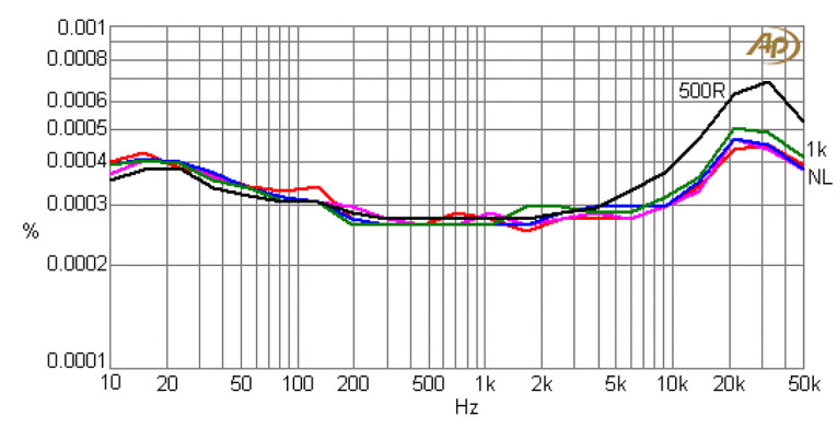
Figure 11 shows the OPA1612 with series feedback. There is now common-mode distortion manifesting above 1kHz; slightly less than for the 5532 in Figure 3. Below 1kHz the THD is significantly lower. Note that the Y-axis has been changed again. (something I do as little as possible here, to minimize confusion)
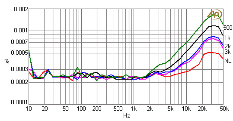
Figure 12 demonstrates the OPA1612 working as a voltage-follower with the usual output loads. Again the 100% negative feedback, and the lack of resistors in series with an input, brings the distortion down so it is barely measurable at 20kHz even when loaded with 500Ω. Much better than the 5532 in Figure 4.
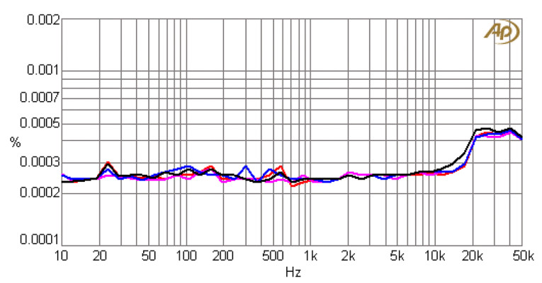
Figure 13 demonstrates the OPA1602 working as a voltage-follower with no output load, but with Rs in series with the non-inverting input. Distortion is markedly increased, even with Rs=1kΩ, and gets pretty bad with Rs=10kΩ, with some added distortion right down to 10Hz. Not much better than the 5532 shown in Figure 5 in this respect.
The LME49860 op-amp. The LME49860 from TI is a BJT-input dual op-amp introduced in 2007; it is described as a “High Fidelity Audio Operational Amplifier” with ultra-low distortion. Unusually for a relatively modern device, it is available in both DIL and SMT.
With shunt feedback as shown in Figure 14, THD at high frequency (above 2kHz) is definitely better than the 5532 for most loads but is about the same with a 500Ω load. It is slightly better below 2kHz.
Distortion with series feedback as shown in Figure 15 is significantly better than for the 5532, and most unusually the THD at 1kΩ load is less than for no-load; I can only attribute this to cancellation of harmonics generated by the early stages with those from the output stage.
For the voltage-follower shown in Figure 16, once again the THD at 1kΩ load is less than for no-load by a noticeable amount. I don’t think I’ve seen an op-amp do this before.
With added source resistance (Figure 17) the THD increases dramatically and is worse than for the 5532 shown in Figure 5.
The OPA209 op-amp. The OPA209 from TI is a single op-amp introduced in 2008. The OPA2209 is the dual version. It is only available in SMT. Strangely the spec-sheet does not say what type of input devices are used, but with an input current noise density of 0.5pA/√Hz it must have BJT inputs. Its main claim to fame is a very low input offset voltage of ±120µV maximum. It is therefore not especially aimed at the audio market, though its precision makes it useful for driving VCA control ports.
The OPA209 distortion performance with shunt feedback is very good up to 1kHz, as shown in Figure 18; at this frequency the THD is claimed on the spec to be less than 0.00001% at unity gain driving 3Vrms into 2kΩ, which is below my limit of measurement. With a 500Ω load the distortion at 10kHz is about half as much again as for a 5532 with the same conditions, and slightly higher at 20kHz. There is no reason to use it if distortion is the issue.
The distortion performance is shown in Figure 19, working with series feedback but otherwise in the same conditions. Distortion is only slightly increased so there is very little input common-mode distortion.
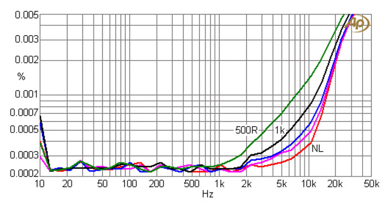
Figure 20 shows the distortion from the OPA209 working as a voltage-follower with various loads. Distortion is notably lower due to the increased negative feedback factor. Distortion at high frequency is about half that of the 5532.
The OPA1602 has less distortion than the NE5532 with shunt and series feedback, and much less as a voltage-follower. Common mode distortion is about the same as the 5532. The OPA1612 has less distortion than the NE5532 with shunt feedback, and about the same with series feedback. It has much less as a voltage-follower. Common mode distortion is about the same. The LME49860 has about the same distortion as the NE5532 for shunt loads, and much less for series and voltage-follower connections. Common mode is worse than for the NE5532. The OPA209 is in general no better or worse than the NE5532. Common-mode distortion is significantly worse. In Part 2, I will finalize the testing of bipolar op-amps and examine JFET op-amps. aX
Read Part 2 of this article — click here
Other Op-Amp Properties
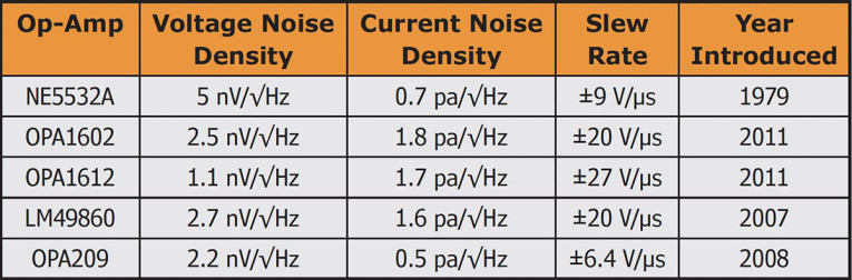
Typical noise densities and slew rate specs for the op-amps tested in Part 1 are summarized in Table 1 below. The low voltage noise density for the OPA1612 is notable. All op-amps have enough slew rate to reproduce a full amplitude sinewave at 20kHz.
Resources
D. Self, Audio Power Amplifier Design, 6th edition, Focal Press 2013, pp. 142-150.