Modifying and building guitar amplifiers is a great experience for guitar players who want to define their sound. Armed with some basic electronics skills, control can be added and optimized for a player’s distinctive sound. Kevin O’Connor’s The Ultimate Tone (Power Press Publishing, 1995) is an excellent resource for anyone modifying or building tube based guitar amplifiers. Another great resource is Douglas Self’s Small Signal Audio Design (Focal Press, 2010). This book does not cover tube circuits or unique aspects of guitar amps but is very thorough on modern electronics design for audio applications. Many Internet resources are also available.
When beginning such a project, it is helpful to use simulators. With modern computing power, simulation of circuits, balanced with practical building, is a must for anyone in electronics at every experience level. Many options exist that have the backing of the Electronic Design Automation (EDA) industry. Two freeware packages related to this topic include the Duncan Amps Tone Stack Calculator and the LTspice. The Tone Stack Calculator includes many common configurations. It also enables users to change the values and evaluate the frequency responses. Linear Technology’s LTspice is a free fullspice simulator anyone can use. It is geared toward Linear Technology’s parts, which may appear to be a drawback. However, the company makes good parts, the tool is valuable, and it’s free, which is helpful for people entering the field.
Preamplifier Overview
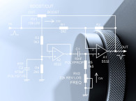
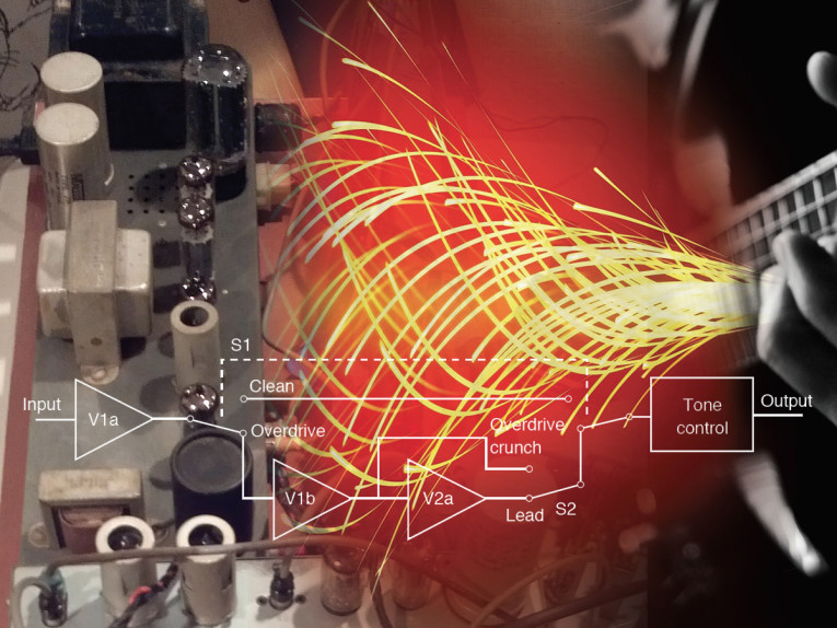
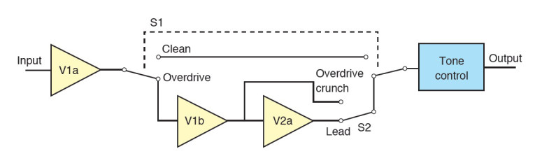
For this project I started with a conceptual block diagram (see Figure 1). V1a provides an input buffer and gain. The combination of S1 and S2 provides three channel selection. S1 selects either a clean channel or one of the overdrive channels. In overdrive, V1b provides modest gain and a crunchy sound. V2a provides extra gain for a well-distorted lead guitar sound. When in overdrive, S2 selects either the Crunch or Lead channel. Tone controls are provided at the output for every channel.
Detailed Circuit Description
Figure 2 shows the tube-based guitar amplifier’s schematic. The schematic follows the flow of the conceptual block diagram. The three gain stages are implemented with 12AX7 gain stages. The tone control at the final output is a standard bass, mid, treble control circuit found in many guitar amplifiers.
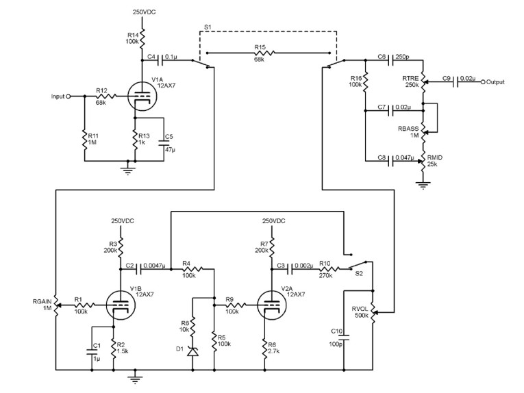
The input buffer stage V1a, is a common cathode stage. The resistor values I used are typical of many common cathode circuits in guitar applications. I chose a fairly large value for C5 to provide a shunt capacitor and maximum gain through the low audio range. C4 is also large for most coupling capacitors and provides a response through the low audio range.
The overdrive gain stages, V1b and V2a, are also common cathode stages. Capacitance values in this section were chosen for their frequency responses and overall tone shaping. The values I selected were optimized based on my hearing preferences and my particular setup. However, you can adjust the values to your particular tastes.
For the first overdrive stage of V1b, I chose C1 to begin to rolloff gain at about 150 Hz. R3 is larger than most anode resistors found in guitar amplifiers, but it can be used to generate a large voltage swing from the output of V1b. Too much bass in a guitar distortion produces a muddy sound. So, I chose C2 for a high-pass effect at about 200 Hz.
I determined the values for V1b with a similar objective. C3 is smaller, but it actually has a similar frequency response because the effective impedance seen by the capacitor is higher. I did not choose a bypass capacitor for R6, reducing the gain. I did it for the sound. For those who want extra distortion, a bypass capacitor around R6 can be added. I opted for D1 and R8 during the circuit’s tune up. Without D1, V2b abruptly goes into cutoff and causes a tearing sound. D1 prevents the grid from going too negative. R8 moderates the diode’s abrupt effect.
Too much high-frequency content above the normal guitar range can cause a shrill sound in distortion circuits. Typically, some sort of rolloff is included in most full-sounding distortion. I selected C10 to roll off the high-end of the distortion channels above about 5 kHz.
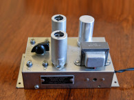
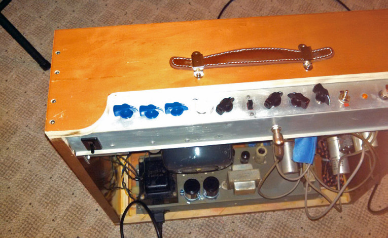
I used the standard configuration found in many well known amplifiers (e.g., Fender, Marshall, and Mesa Boogie) for my tone control circuit. The amplifier’s design resulted in a versatile range of guitar tones for a fairly simple circuit. Any specific component value choices can be adjusted to tailor the sound to the particular guitar player, the player’s style, and the player’s choice of sound (see Photo 1).
The power supply and the tube heater sections are not specifically shown, but they are assumed to be incorporated as part of the overall guitar amplifier construction. I encourage you to use high-voltage bypass capacitors entering every anode resistor. I used 250 VDC for this circuit, but the exact value is flexible certainly ±10% to ±15%.
Output Interface
The circuit shown in Figure 2 has a high-output impedance and is intended to connect to another common cathode tube stage (see Figure 3a). An output buffer should be added for interfacing to a lower impedance or for a standalone preamplifier to a variety of loads. Figure 3b shows a cathode follower configuration. If lower DC power supply voltages are available, an op-amp buffer provides a versatile low-cost approach (see Figure 3c).
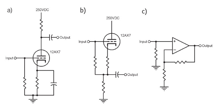
cathode (a), a cathode follower (b), and an op-amp buffer (c).
Many construction methods are suitable for this design. But, be careful to minimize stray capacitance. Tube circuits work at high impedances and stray capacitance from ground planes or extra shielding attenuates the upper frequencies. This, according to many players, “robs the tone.” I encourage anyone using this design to shield the critical small signal sections for low noise. However, for this circuit, it is only necessary on the guitar input signal.
was conducted with the prototype connected
to the organ amplifier’s remaining sections.
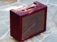
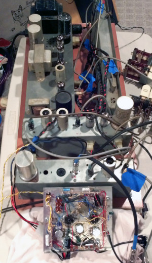
I conducted a complete test of the preamp with the rest of the power amplifier section before I gave the amplifier to my friend to mount in his cabinet. Photo 3 shows the preamplifier with the organ amplifier’s remaining sections. The complete setup created a vintage sounding tube-based guitar amplifier. The preamplifier provided the missing tone controls and overdrive needed to convert the organ amplifier into a versatile guitar amp. ax
Resources
K. O’Conner, The Ultimate Tone, Power Press Publishing 1995.
D. Self, Small Signal Audio Design, Focal Press, 2010.
Sources
Tone Stack Calculator
Duncan Amps | duncanamps.com
LTspice
Linear Technology | www.linear.com
About the Author
Peter Delos is a Radio Frequency (RF) Circuit Design Engineer at a major electronics company in the greater Philadelphia, PA, area. He is also a guitar player. Peter began modifying and designing guitar amplifiers for gigs and recordings when he couldn’t buy what he wanted. He does guitar amplifier repairs, modifications, and custom designs for local musicians and friends.
This article was originally published in audioxpress.com, October 2014.