Maybe.
I’ve discovered that it’s possible to dramatically reduce the intermodulation distortion in class A filamentary triode tubes by reducing the filament voltage. If this has been noted before, I’m not aware of it.
Before members of the “Society for the Preservation of Olde Tubes” start putting their quills to parchment, let me say that this is experimental. For the sake of tube life, I recommend only a moderate reduction in filament voltage and the use of lower-than-normal signal voltage until we know more.
The Theory
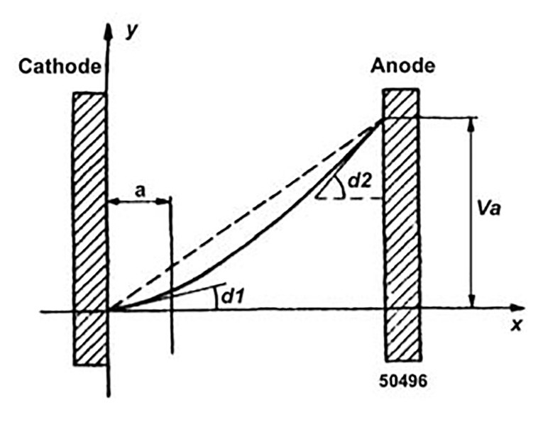
I believe the most important reason for the drop in distortion with the lowering of filament voltage is the reduction of the space charge. This makes the potential distribution across the tube more linear. The space charge is the cloud of electrons that usually surrounds the filament (or cathode) of a vacuum tube. Some of these electrons are drawn away to the grid/plate system, but others remain in the vicinity of the cathode and actually can repel some electrons, forcing them back to the filament.
You’ll find a good explanation of this in Fundamentals of Radio-Valve Technique, by J. Deketh1. Figure 1, from page 18 of the text, shows how the potential distribution across the tube becomes linear without the space charge and how all the electrons go directly to the grid/plate. Reducing the voltage below the point where the space charge disappears or operating the tube at too high a signal level can damage the filament.
The Data
I first noticed this drop in distortion when I accidentally reduced the filament voltage while making intermodulation tests on an amplifier using a 71A. I thought perhaps there might be some peculiarity about the 71A, the battery bias I was using, or the DC on the filaments. So I repeated the test using a 2A3 with self-bias and the standard 750Ω resistor, and a bypass capacitor and AC on the filament. The results were similar.
I had been using the standard SMPTE method with frequencies of 60Hz and 6kHz at a voltage ratio of 4:1. I thought perhaps one frequency or the other was somehow being attenuated, so I repeated the test using the CCIF method. I used frequencies of 15kHz and 16kHz and measured the 1kHz difference, which was almost identical to the results obtained with the SMPTE method.

Other components in the circuit, such as the output transformer, also have an influence. The test conditions are important, too. Filament voltage is only an indicator of emission, which is proportional to filament temperature. There is a time lag between setting a filament voltage and stable emission at that temperature. Taking readings as the filament voltage is increased will be slightly different from taking readings as the voltage is decreased, unless you allow enough time between measurements.
I made extensive measurements with RCA 2A3s using two sets of parameters. In the first, the plate voltage and power output were held constant. This would represent a situation in which a new amplifier was designed for a given output and plate voltage. In this case the plate current dropped as the filament voltage went down, while the input signal had to be increased to compensate for the reduction in gain.
To be sure the intermodulation distortion reduction was not unique to single-stage amplifiers, I built a twostage amp with a type 30 filamentary triode voltage amplifier. By carefully adjusting the filament voltages of both the 30 and the 71A or 2A3 output tube while adjusting components for maximum cancellation, I was able to achieve a very low value of IM distortion. What a fine-sounding amplifier it was! However, this article is not about one specific amplifier but a general presentation of the reduction of intermodulation by adjusting the filament voltage.
In addition, I checked the 2nd and 3rd harmonic output while lowering the filament voltage. The decrease in 2nd harmonic distortion corresponded to the reduction in IM distortion, as could be expected since the distortion of triodes is primarily 2nd order. However, the 3rd harmonic distortion, although very low, increased slightly. If the lowering of distortion was due to negative feedback, both 2nd and 3rd harmonic distortion could be expected to decrease.
Downsides
The first is signal level. To minimize shortening of the life of the filament, I don’t recommend this technique at the normal output level of a tube. I suggest that with a 2A3, for instance, the music peaks probably shouldn’t exceed 1W very often. Because of the logarithmic nature of the ear and the fact that most of the music is below that, you might not even notice the difference2. Remember, this is experimental.
I’m not sure there’s enough data available to make a definitive statement. The days when you could take a hundred 2A3s off the line and measure tube life against filament voltage are over! Perhaps readers can report their results through audioXpress. I wouldn’t recommend trying unused new-old-stock (NOS) tubes, both from the standpoint of cost and also because the extra emission of new tubes may give misleading readings until they age a bit. I also wouldn’t try this with very expensive tubes such as Western Electric 300-Bs until we have more information.
Third, finding the best operating point requires some test equipment, at least enough to measure filament voltage and plate current. But anyone using tubes really should have a way of measuring these, especially filament voltage. Line voltage is considerably higher in many areas than it was during the tube era, and you may be surprised to find that your 6.3V tubes are being subjected to well above 7V. This will definitely shorten tube life!
I suggest not going below 80% of the rated filament voltage without means of measuring either intermodulation distortion (preferred) or 2nd harmonic distortion or THD. I think the best course is to reduce the filament voltage to a value above the point of absolute minimum distortion. This will give a safe margin to compensate for loss of emission as the tube ages, fluctuation in line voltage, and so on, but still give a significant reduction in IM distortion.
Finally, a separate source of filament voltage for only the output tube is required. However, a separate filament transformer for triode output tubes is often used anyway, because they often require different voltage than the usual 6.3V tubes used elsewhere in the amplifier.
Lowering the intermodulation distortion produced in filamentary triode tubes through control of the filament voltage may prove to be a very useful technique. It may be used for voltage amplifiers or for output tubes at reduced levels. I’ve never seen anything about it in print and would welcome any information to the contrary. While it may not be needed in some amplifiers, it may prove to be a valuable alternative to negative feedback or cancellation in reducing distortion. aX
This article was originally published in audioXpress, May 2005.
References
- Reprinted by Audio Amateur Press, (603) 924-9464, custserv@audioXpress. com, ISBN 1-882580-23-0, $29.95.
- A 2A3 is rated in the manuals as putting out 3½W at 5% distortion. This doesn’t include transformer losses, the voltage reduction from using self bias, and so on. The restriction to 1W on peaks probably represents only a 3 or 4dB actual decrease.
- Also from Audio Amateur Press, ISBN 1-882580-29X, $14.95