Through the years, many tube amplifier designs were born in my labs. It appeared to be a long and never-ending search for the real sound. In my youth, I started with standard designs, such as 2xEL84-PP with a switch to select none or strong global feedback. Now, after many years, I present an approach where local feedback is dominant. The scientific opinion is that global and local feedback theoretically are the same. My tube amplifier practice shows that this is certainly not the case.
There is for instance a major difference if the output transformer is inside or outside the feedback loop. To briefly summarize my observations on tube amps: Global kills details while local keeps those alive. Therefore, my present design strategy is: per amplifier section, first cure its “faults” by means of local feedback. This article shows how to do that. One extra remark: No feedback at all keeps details alive, however, it can sound uncontrolled. Local feedback keeps all the details alive and sounds clean and controlled.
A Bit of Valve Amplifier History
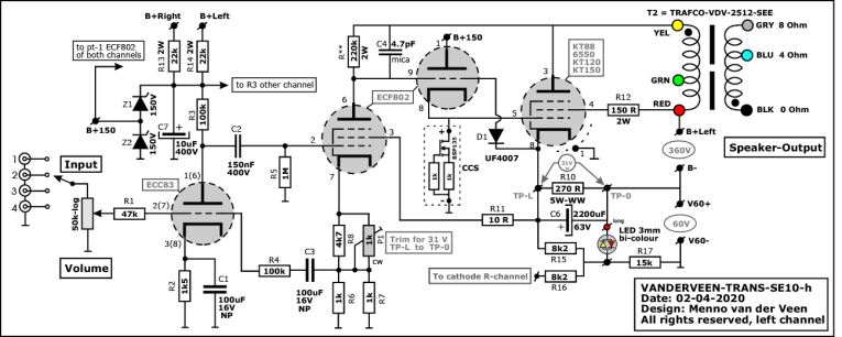
The complete audio circuit of the Trans-SE10 amplifier is shown in Figure 1. Before I explain it in detail, I want to first delve into valve amplifier history to show the important sources of this design. In the early days of tube amplifiers, many important research articles were published. Two of them play a major role in the Trans-SE10. The first is from N. Partridge about magnetic distortions in output transformers [1]. The second is from Otto H. Schade about beam power pentodes [2].
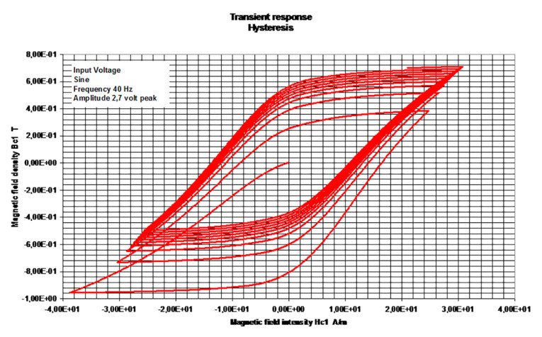
Partridge researched magnetic distortions in transformer cores, created by nonlinear behavior (hysteresis) of the magnetic flux inside the core (Figure 2). Because amplified audio voltages from the power tube to the loudspeaker pass through an output transformer, the loudspeaker voltage will get distorted as well. He proved that the magnetic voltage distortion at the loudspeaker terminals is largely determined by an external factor: the plate resistance rp of the driving power tube. The smaller rp, the smaller the magnetic voltage distortion. This conclusion plays a major role in the SE10.
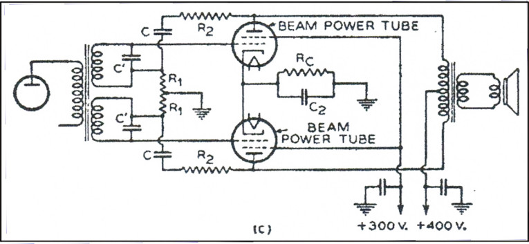
Schade researched beam-power pentodes. Almost at the end of his publication, he introduced a special local voltage feedback from the anode directly to the control grid of the power tube. See his circuit shown in Figure 3. Schade did not apply global feedback from loudspeakers output to amplifiers input (the standard method), but only locally around the power tube. Trained listeners gave a very high score to this method — it sounds much better than global feedback.
I tested it and indeed, it sounds very natural. I made some important observations in my youth at the age of 15 [3]. With the help of an engineer, I built my first EL84 push-pull amplifier. I noticed that the EL84 in pentode, switched to no feedback, was excellent for my electric guitar. However, in triode, the amp sounded much cleaner. Also, with one EL84 removed (push-pull changed to single-ended), I appreciated the sound character as more natural.
In all configurations, with global switched on, the sound became flat and lifeless. As youngster, I was unable to explain my observations. Years later, I understood and applied the knowledge in this new SE10 design.
Previously, I mentioned two literature sources and some personal observations. Everyone knows there are abundance of high-quality articles and observations. But why burden you with a huge literature list? The three mentioned here are enough to explain Trans. So, let’s start.
Magnetic Voltage Distortions
I deeply researched toroidal output transformers for valve amplifiers and brought my designs worldwide to market. Toroidals, such as the one shown in Figure 4, have the advantage of a large primary inductance, a low leakage inductance, and a small interwinding capacitance. As a result, from deep-low to ultra-high, the frequency range is very wide without nasty resonances. In past publications, I explained a lot about the frequency behavior of my transformers (see References). This time, I will focus on the transformer core and its magnetic distortions.
Transformer cores are made of special steels, for example, Grain-Orientated Silicon Steel (GOSS). Inside that steel, we find the magnetic Weiss domains. They change their orientation when the output tube sends its music current through the primary winding. This current creates a magnetic field H, and the core becomes more or less magnetic in the rhythm of this music. The steel has an index that indicates how strong the core supports and amplifies the magnetism because the Weiss domains change their orientation more or less along the field lines. We call this index the relative magnetic permeability μr.
In the example about GOSS material, this μr has a maximum value of 30,000, which means the core amplifies the magnetism 30,000 times. But it also says that μr is not a constant index. It changes when H gets larger or smaller. Consequently, the effective magnetism (flux density B) in the core is not linear with H and also can get saturated and also has a memory (B = μo×μr×H). This certainly is not linear behavior, and it implies magnetic voltage distortion.
Let’s go back to Partridge in 1939. He states: “If the power tube that drives the transformer has a small plate resistance rp, then the magnetic voltage distortion will be small. But, be aware, when rp is large, then the magnetic voltage distortion will be large—a linear relation.”
What is this rp? Let me explain with some examples: A triode such as the famous 300B has a rp value of 700Ω. However a pentode such as the EL34 or KT88 has a rp value environment 10kΩ.
Meaning: if we make an amplifier with a 300B and this amp distorts magnetically 0.5%, an equal EL34 amp will have 0.5% x 10000/700 = 7.2% magnetic voltage distortion. This is impressive more than with the 300B.
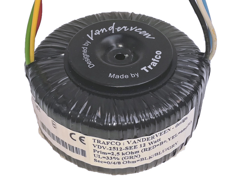
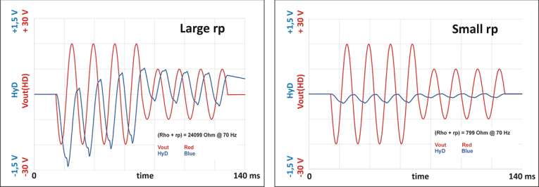
Figure 5 shows some examples of magnetic voltage distortion (indicated as HyD, meaning Hysteresis Distorion). Small magnetic distortion is one of the reasons why 300B triode amplifiers sound so clean compared to dull sounding EL34 pentode amplifiers. (The change in medium 300B damping factor to very small EL34 damping factor is another important factor, not discussed now.)
To be more complete in my explanation, I need to make two remarks: These results are valid in the low-frequency range. Second, the tube itself (300B or EL34) distorts the voltages as well, but this is not magnetic distortion. I will deal with tube distortion when discussing the Trans principle.
Summarizing: if you wish the lowest magnetic voltage distortions in your output transformer, apply low rp power tubes. Which tubes do we find in the world’s best high-end amplifiers? The 300B and many other fantastic directly heated triodes, such as the 211 in the world-famous Ongaku amplifier.
Top designers know this Partridge rule and have it chiseled in stone above their test bench. [For the diehards: Make an air-gap in the core and the magnetic voltage distortions are gone. Careful: Partridge proved that per frequency the ratio between rp and Lp determines the distortion reduction. Gapping makes Lp smaller and consequently the effective magnetic voltage distortion is not that simple to calculate.]
The Trans Principle
There are several methods to create low plate impedance power tubes. I will list them and focus next on Trans.
Apply low rp triodes, such as the 300B, the 6AS7, or the 6C33 (voltage supply regulator tubes are excellent in low rp aspect) or the larger 211 (VT-4C) and the like. Or apply local feedback at the tube’s cathode (Audio Research and Quad II). Or apply the Ultra Linear principle of local feedback at the screen grid (Hafler and Kerous). Or combine cathode and UL feedback (unity coupled: McIntosh). Or follow the Shade approach shown in Figure 3. Or use Menno’s Super-Triode approach. Or apply feedback from the anode of the power tube to the cathode of the driver tube. And so on!
The tube amplifier world is filled with the finest inventions. All these methods have in common that the local feedback is partly applied, not 100%, although McIntosh is extremely close. Trans creates 100% local feedback, as is the cathode follower approach [4], as are the MTA inventions [5],[6]. I know there are more fantastic solutions, but I can’t discuss all of them. For more information, see my The-Project study [7], where I evaluate most of these methods in detail. Next, I will focus on Trans only.
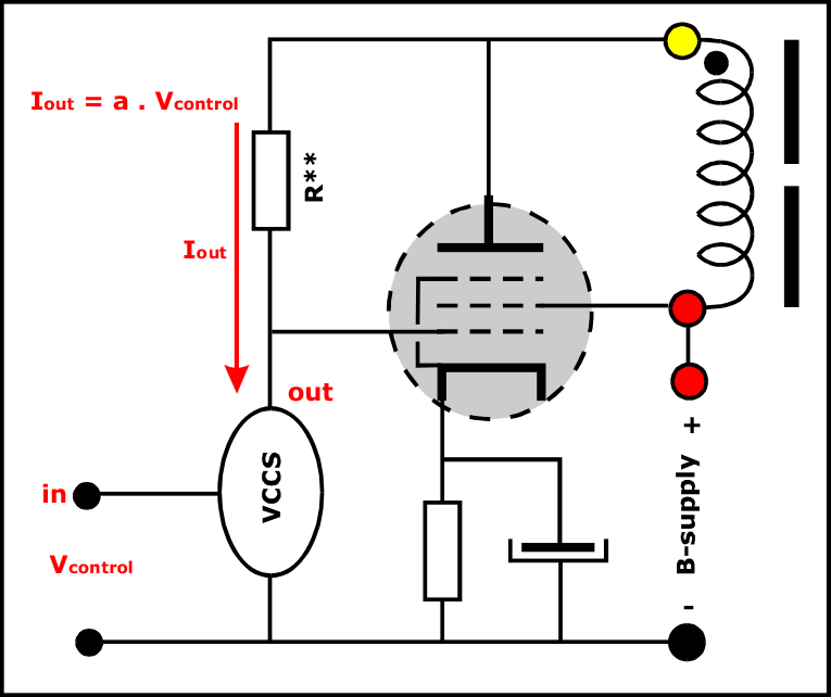
Suppose I have a pentode power tube with a plate resistance rp = 10 kΩ, an open-loop amplification factor of 200, and an internal tube voltage distortion of 5%. Suppose I use all its amplification to correct its own mistakes (a correction of 200 equals 46dB local feedback). What will be the specs of this new Trans-Tube? Its new plate resistance will be 10000/200 = 50Ω. The new amplification factor will be 200/200 = 1 and the new tube voltage distortion will be 5/200 = 0.025%. These new specs are better than any available tube on the market. So let’s do it (Figure 6).
Added to the pentode is a voltage-controlled current source (VCCS), which simply means: a device that delivers a current output. The currents magnitude is only determined by the controlling input voltage. At its current output, the VCCS has an infinitive internal impedance. The VCCS output current only runs through a special R** resistor, which is directly connected between the anode and the control grid of the pentode. How does this function?
First, seen from the power tube: All voltage variations at the anode appear 100% at the control grid because the internal impedance of the VCCS is infinitive. There is no loss inside the VCCS. The control grid even does not notice the VCCS. The control grid only sees the R** connection. This is equal to 100% feedback, and the nice specs mentioned are the result.
Second, the variable music current Iout runs through R** and creates a changing voltage over this resistor, which drives the control grid of the power tube that next drives its anode.
Third, seen from both sides: a coupling capacitor between the control grid of the power tube and R** is not allowed. Such a capacitor would combine its phase shift with the phase shift created by the primary inductance Lp of the output transformer. This would result in more than 90° phase shift in total, causing ugly motorboating (low-frequency oscillation). For proper operation down to the lowest frequencies, capacitor-less direct-coupling is a must. This condition is difficult in practice, but advantageous because the sound of a coupling capacitor will be absent [8].
See additional article references [9], [10], [11] for more and deeper explanations or other approaches. For now, this short introduction is enough to proceed to the next stage.
VCCS Realization with ECF802
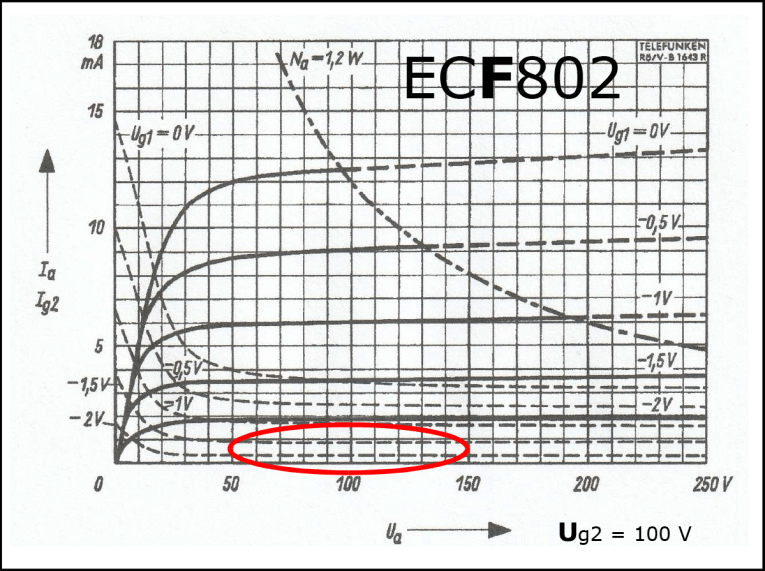
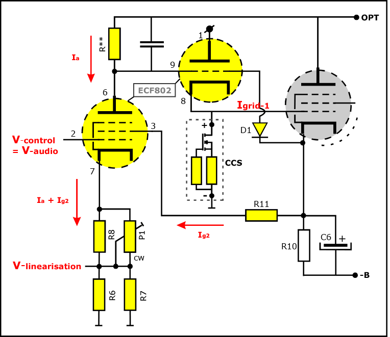
After many experiments I decided to make an all-tube VCCS. With good reasons I selected the ECF802, because its pentode characteristics has a nice linear part, indicated in red in Figure 7. In this linear part the screen grid current Ig2 of the F-section is constant, which is a mandatory condition. In the next section about linearization, I will improve the linear relation between the control voltage at the control grid and the current source output Ia at the anode of the ECF802 (Figure 8).
In that circuit I measure the cathode current Ik to know Ia. However, the cathode current Ik contains (Ia + Ig2). Meaning: when Ig2 is constant, the alternating (music) part of Ik will equal the alternating (music) part of Ia. See the next section for further details.
I placed a cathode follower between the R**-VCCS connection and the control grid-1 of the power tube. The reason why is the Miller capacitance between grid-1 and the anode of the power tube. In power pentode tubes the screen grid shields the anode from grid-1, but still there is some residual Miller capacitance. Consider this Miller capacitor in parallel with R** and you will understand that the high-frequency bandwidth gets restricted.
The cathode follower shields R** from the Miller capacitance and prevents this bandwidth restriction. Another reason for the cathode follower: grid-1 of the power tube might draw some grid-current (although little, but still) that could create extra harmonic voltage distortion. The cathode follower shields R** from any control grid current. So, it is there for very good reasons. Next, a purist might argue: Why a field-effect transistor (FET) current source at the cathode of the follower instead of a normal cathode resistor? Just to make the distortion of the cathode follower lowest, but you are absolutely free to replace the CCS by a 27 kΩ 0.5W resistor.
Two additional remarks: The diode D1 between R** and the cathode of the power tube prevents positive grid-1 voltages with respect to the cathode at start-up of the amplifier. Second, the cathode current of the power tube creates an almost constant voltage over the R10-C6 combination. The more quiescent current, the larger this voltage. The screen grid of the F-section of the ECF802 senses this voltage with R11 and creates a quiescent current feedback, stabilizing the operation point of the power tube.
VCCS Linearization with ECC83
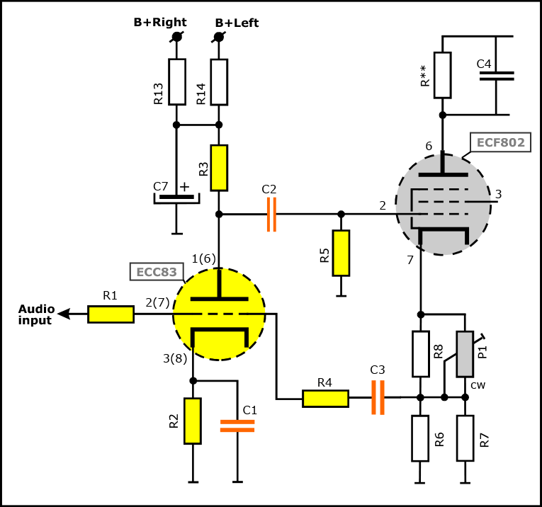
In spite of the good ECF802, the linearity of the current source was not good enough; some residual distortion was noticed. To improve linearity, I created an independent second local feedback circuit with an ECC83 (one triode section per channel). This new circuit (Figure 9) has two inputs: the audio signal input via R1 and the VCCS current sensing input with R4. (For now, forget the coupling capacitors C1, 2, 3. I will deal with those in a moment). The large amplification of the triode section (factor 60) is reduced to R4/R1 = 2. So, a factor of 30 is available to make the current of the VCCS “absolutely equal” to the audio input voltage.
Gone were the residual VCCS distortions. This is a local feedback of 30x = 30dB, highly linearizing the VCCS. Imagine such 30dB plus the earlier mentioned 46dB (76dB in total) as a global feedback from amplifiers output to its input in an old fashioned tube-design. Absolutely impossible! Total instability would be the nasty result. Only with local feedback sections can you do such a trick.
In this extra ECC83 local feedback section, only AC voltages (music) play a role. So, coupling capacitors are allowed, making life (design) much easier. But capacitors do sound [8]. Yes, but their sound is weakened by 30dB feedback, and not noticeable anymore. Well, let’s apply cheap ones.
Please not; I applied good ones. Recently, one of my TubeSociety students used a very expensive C2 and heard further improvement. This underlines my statement to use good quality capacitors. (It also says: Feedback is not completely able to suppress capacitor distortion. But that is another research topic.)
Also, the local feedback ECC83 circuit should operate perfect from almost DC level to get the optimal VCCS linearity. That explains the rather large capacitor values. Don’t change these, or else the VCCS and power-tube and OPT cooperation will not be optimal anymore at the lowest audio frequencies.
(For the diehards: C1,2 are interrelated to create a first-order high-pass behavior of the ECC83 section; see chapter 4.4 in my book High-End Valve Amplifiers [12]. Capacitor C3 creates an extra high pass filter, but its corner frequency is way below the C1,2 corner frequency, and therefore not disturbing.)
Measurements and Explanations
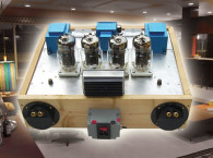
In this article, I will not pay attention to the case and construction of the Trans-SE10 amplifier. Please download the construction manual [13]. I also will not discuss the power supply section. Equivalent circuits were applied in earlier publications [14],[15],[16].
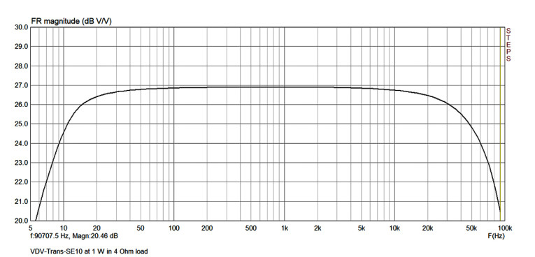
The frequency characteristic shown in Figure 10 shows excellent behavior from 9Hz to about 60kHz (-3dB frequencies). No ringing or oscillation is noticed, thanks to the applied toroidals. This all looks great and needs no further remarks, only that at the onset of clipping, the amp is capable of 12W output power. On purpose, the SE10 number is a modest number.
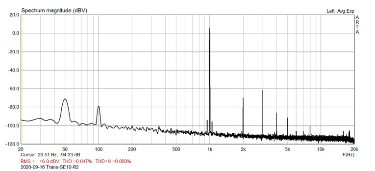
The next measurement (Figure 11) shows the 1kHz harmonic distortion spectrum. The second harmonic is equal or lower than the third, depending on the ECF802 tube brand. That is unusual in single ended tube amps. The power tube has such a small Trans-rp (which reduces magnetic OPT distortions) and such small internal tube distortions (due to the local Trans-feedback), that the standard declining harmonics spectrum is not observed anymore. I discussed this effect earlier [14],[15],[16].
When you study my article [14] in detail, I describe my observation that standard declining harmonics is pleasant, but also has a curtain (the H2-curtain; from Keith Howard’s article “Euphoric Distortions” [17] calls it “muddy”) in front of the soundstage, making finest details not noticeable anymore.
Only with amplifier 4 [14] and amplifier 5 [15], was I able to remove that curtain. I demonstrated this effect to a group of experts at the European Triode Festival (ETF) 2019 in France. They agreed with my observation and referred to studies where similar results are discussed [17], [18].
I had very good reasons to discuss it all at ETF. The general opinion is that declining harmonics gives “The Great SE-Sound.” Now I conclude: “declining harmonics hides details; H2 has to be minimal.” This is like cursing in the church. Think of the great work of Jean Hiraga, who taught us about the marvelous Japanese single-ended amplifiers, where the declining harmonics rule governs. With Trans, I clearly deviate from this generally accepted rule. I invite you to listen to Trans and judge for yourself.
The next reason to discuss it all at ETF is that magnetic distortions are largely suppressed. Normally, this is partly done by means of global feedback. But everybody knows that global feedback exceeding 20dB surely will create instability due to resonances in OPTs. Remember, Trans creates about 46dB of feedback locally in front of the OPT.
Therefore, Trans suppresses magnetic distortion much more. So, one could wonder: is it the Trans H2-reduction or the Trans magnetic distortion reduction that creates the clearer details, or is it both? I think both. My research in articles [14],[15] showed that H2-reduction removes the curtain. However, amplifier 4 (with Trans) was better than amplifier 5 (with H2 pre-distortion compensation).
Youth Observations Explained
Let’s go back to my observations at the age of 15. I noticed in my first EL84-PP amplifier with global feedback switched off, that EL84’s in triode mode sounded cleaner than EL84s in pentode. This is logical: triodes have lower rp. So, the magnetic distortion of the OPT was smaller. Also, triode mode means internal feedback inside the EL84s. So, the tubes operated cleaner. This observation is fully explainable with our present insight. But there is more: push-pull minimizes H2. So, my first EL84-Triode push-pull amplifier was going direction Trans. At that age, I was totally unaware of this.
What is there to say about my guitar preference for pentodes? I liked the brown bluesy distortions and that preference has not changed over the years. Let‘s look at my other observation with one EL84 removed from the Push-Pull (PP) amp. In fact, I listened to a non-ideal single-ended (SE) amp with standard declining harmonics and I liked that sound.
How to explain the unalive sound with global feedback switched on? Let’s say it in normal language: “The feedback was unable to correct all the faults in my starters amplifier and made a mess of it.”
Is That All There Is?
I noticed in the reactions of my students and SE10 listeners that they did not recognize the two local feedback sections, nor the fundamental reasons why I created them. I hope this article will support their understanding. How I calculated component values and so on? That will be a totally different story, way beyond my goal to explain its fundamentals. For that reason I will stop now.
Allow me to add one remark overviewing my research on tube amps. For years, I followed the global feedback trail. Next I changed to no feedback at all. Now I research local feedback and it feels like having gold in my hands. Its essence is: “Cure before you apply.” That’s it.
Summary
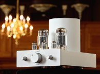
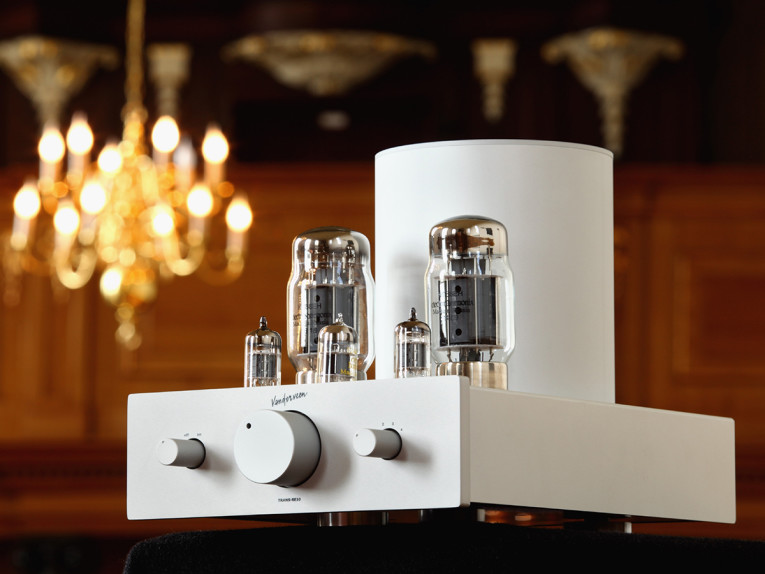
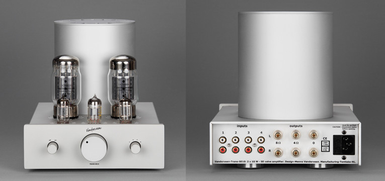
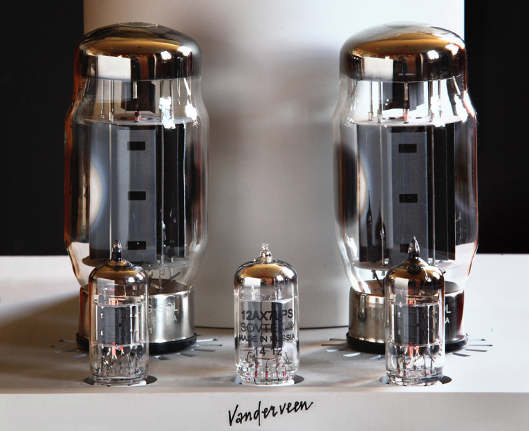
The new Vanderveen Trans-SE10 is a challenging DIY kit. It clearly demonstrates what benefits can be gained with local feedback in relation to detail reproduction. Its concepts are deeply rooted in tube-amp history. The Trans technology lowers tube and output transformer distortions substantially, allowing to enter new areas of valve amp sound reproduction.
What future progress can we expect? Presently, I am researching Trans with my TubeSociety students in high power (up to 100W) push-pull Class-AB tube amplifiers. When ready, I plan to share it in one way or another. Please be very patient! Research dictates its own pace (and the coronavirus certainly does not help). aX
This article was originally published in audioXpress, January 2021
References
[1] N. Partridge, “Distortions in Transformer Cores,” The Wireless World, June 1939.
[2] O. H. Schade, “Beam PowerTubes,” RCA Radiotron Division, RCA Manufacturing Co., Inc.
[3] M. van der Veen: personal observations in 1964
[4] P. Touzelet, “The Trans-driven Cathode-Follower Amplifier,” work in progress
[5] F. Blöhbaum, “Multiplied Transconductance Amplifiers, Part 1,” Linear Audio, Vol. 6, pp.83-91.
[6] F. Blöhbaum, “Multiplied Transconductance Amplifiers, Part 2,” Linear Audio, Vol. 8; pp.31-50,
[7] M. Van der veen, www.mennovanderveen.nl > research & development > publications > amplifiers > 2005: The Project
[8] The works of Ari Polisois, who refused to use coupling capacitors, with impressive results.
[9] J. Macaulay: “Hot audio power”; EW + WW; October 1995, pp.856-859.
[10] M. van der Veen, Vanderveen Trans Tube Amplifiers, Elektor, ISBN 978-1907-920349.
[11] J. Broskie: www.tubecad.com/2014/09/blog0305.htm
[12] M. van der Veen, High-End Valve Amplifiers 2, Elektor, ISBN 978-0-905705-90-4
[13] M. van der Veen, ‘’Vanderveen-Trans-SE10 Construction Manual,” www.mennovanderveen.nl
[14] M. van der Veen, “TubeSociety 2A3-300B-SE Amplifiers, Part 1,” audioXpress, April 2018
[15] M. van der Veen, “TubeSociety 2A3-300B-SE Amplifiers, Part 2,” audioXpress, May 2018.
[16] M. van der Veen, “Build an 18 W Single-Ended Valve Amplifier with Trans Technology,” audioXpress, December 2019.
[17] K. Howard, “Euphonic Distortions” Stereophile, www.stereophile.com/reference/406howard/index.html
[18] P. Millet, “The Sound of Distortion,” www.pmillett.com/etf_sod.htm
 About the Author
Menno van der Veen studied technical physics and electronics at the “Rijks Universiteit Groningen” in the Netherlands. From 1976 to 1990 he taught physics at a high school and a teachers training College. Weekends he worked as sound engineer in a small alternative theater and was sound coordinator for big outdoor events. As reviewer, he wrote many articles for Dutch high-end audio magazines, evaluating audio amplifiers. In 1986, he founded his “Vanderveen” company with focus on valve amplifiers with toroidal output transformers.
In cooperation with manufacturers worldwide he designed his new range of Vanderveen-toroidals and regularly reported about research results in Audio Engineering Society (AES) convention papers. Menno was chairman of the Dutch AES section and co-organizer of AES conventions in The Netherlands. In 2005, he founded a bi-weekly Saturday school, called “TubeSociety,” with the goal to share his specific tube amplifier knowledge with enthusiast do-it-yourselfers. In his private hobby time, Menno devotes a lot of research on electronic guitars, their valve amplifiers and effect pedals, almost never publishing research results. He says, “When making music yourself, you train your ears in the search for the sublime guitar sound.” These skills, combined with electronics knowledge, are the powerful tools he applies when designing new audio equipment.


