
DIY audiophiles considering building a single-ended (SE) amplifier are prepared to accept a limited power output — compared to a push-pull amplifier — for many reasons. First of all, they know that two output valves in a push-pull configuration can deliver quite a lot of power; whereas, the same tubes in a single-ended circuit deliver about one quarter of that power. In a SE amplifier, the magnetic circuit of the output transformer is constantly (and from the start) magnetized by the idle plate direct current of the power valves, up to — and sometimes over — half of its capacity, leaving less than half of the total headroom to the alternating currents of the amplified signal.
On the other hand, in a push-pull amplifier’s output transformer, the two half primaries produce opposed fields that cancel each other. As a consequence, these OPTs (output transformers) can be smaller for the same power handling. Mostly for these reasons, SE amplifiers (commercial or custom built) seldom have power outputs in excess of 10W (more frequently 5 or 6W), unless high voltage power valves, such as the 845 or 211, are used. Naturally, the latter amplifiers are more expensive, because they require more sophisticated and critical circuits and components, not to mention the danger of very high voltages.
Times have changed, and new solutions have made some configurations obsolete, or, to be more precise, have allowed SE amplifiers to become more like push-pull ones. My article in July 2004 (“High Power SE 6C33C Amp,” p. 20) described a SE amp delivering 50W per channel.
This article will provide more information on how to further simplify the whole construction and reduce the costs. I will not deal with theoretical ideas or expectations. The results, having been obtained with units already assembled, combine the advantage(s) of the push-pull (mainly power) to the wonderful character of the SE: sensitivity, smoothness, simplicity, and warmth (due to the 2nd harmonic content, easily tolerated by our ears, as against the third, fifth, seventh, and so on harmonics produced by the push-pull).
I will use triodes — except in the power supplies, of course — and it will have direct-coupled stages, working in Class A. The layout belongs to the family of the SE amplifiers, but, to be more specific, it is double ended.

SE Handicaps
Finding them does not take much effort nor time. The responsible component is the output transformer. The more power you need in the SE layout, the sooner this critical unit becomes bulky and heavy, unless you can find a way to avoid magnetizing that half of the core’s headroom that I mentioned previously.
At first glance this looks impossible, but it’s not. Don’t forget that this is already obtained with the push-pull transformer, in which the voltage applied to the center tap separating the two primary half windings flows to the valves through two coils having an opposed winding sense. Because the number of turns is the same, the two magnetic fields produced in the core by the DC (direct current) cancel each other, provided the currents are of the same intensity. This simply means that the full core magnetic headroom (or most of it) is available for the alternating current voltage swings produced by the output valves.
In a push-pull amplifier, each channel is completed with one output transformer (Fig. 1), and the two half primaries receive opposed modulations from the “push” valve and the “pull” valve. This is compulsory; otherwise, the alternating current swings would also oppose and cancel each other. For this reason, either a phase inverter or a phase splitter is necessary to feed the push and pull valves’ control grids with opposed signals.
Also, in the PP OPT (push-pull output transformer), there is only one secondary that collects the induced signals and transfers their energy to the loudspeaker1. A typical PP amplifier — from the input terminals to the output ones of each channel — includes the following:
1. A voltage amplifying stage (generally one or two valves)
2. Phase splitter or phase inverter system
3. Driver stage
4. Power stage
5. Output transformer
Plus, the relative power supplies for the heaters and anodes.
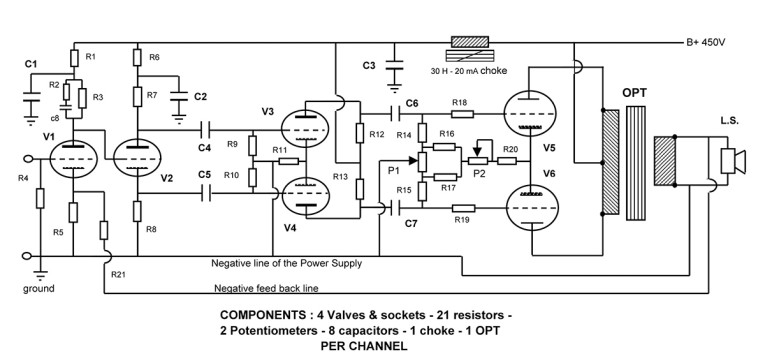
Figure 2 displays the schematics of one channel of a well-known classic unit, the famous Williamson. A more modern layout has been introduced by Menno van der Veen with his ST40 amplifier - mennovanderveen.nl).
Action
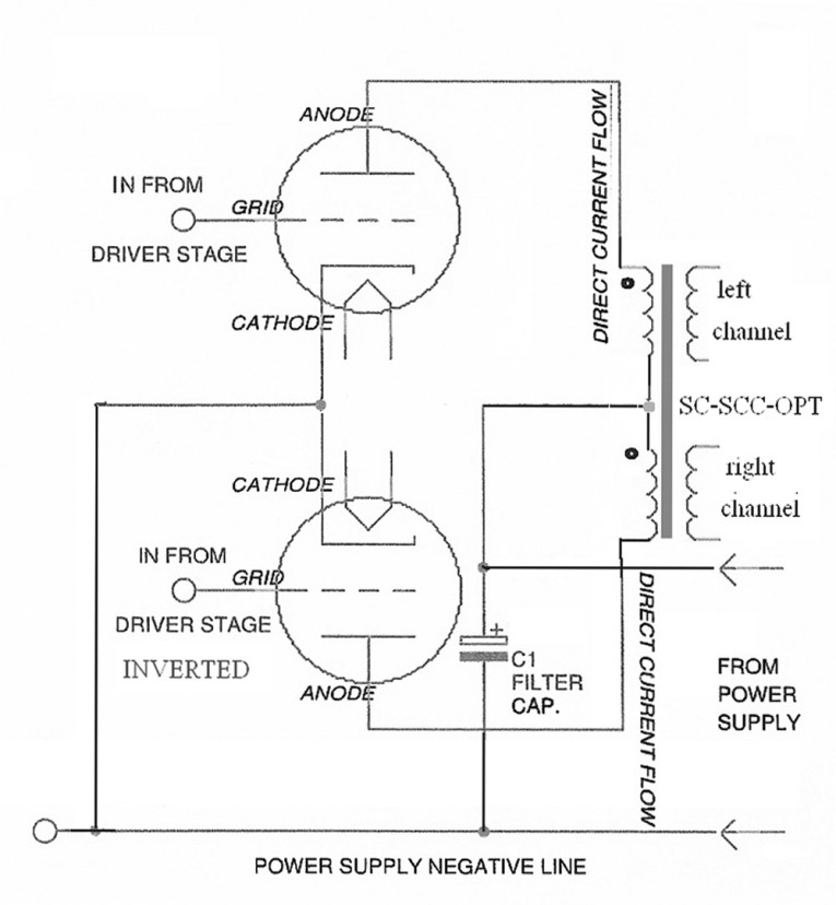
Consider only three of the stages — 1, 3, and 4, one set for the right channel and one for the left channel, skipping, for the time being, the inverter or phase splitter system. Do not use an output transformer for each channel, but just one novel output device for both channels2. This device (Fig. 3) might at first look like a PP transformer, because the theoretical layout is the same, but, in practice, there are some significant differences.
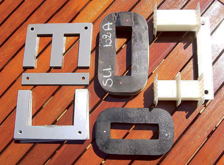
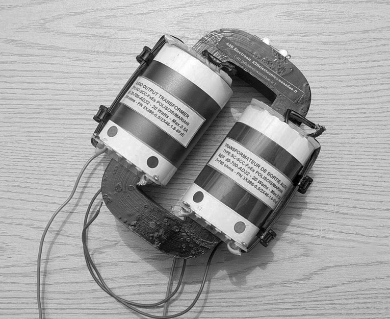
First, the two primaries are not closely coupled, as in most PP transformers, but they are located each on one branch of a “C” or “UI” core, or a three-phase lamination stack, with the middle leg removed (Photo 1). Second, there are two secondaries (one for each channel output), coupled as closely as possible to their respective primaries3.
Reaction
The two SE channels have been enclosed in just one output transformer, the SC-SCC-SET (split-core, stereo common circuit, SE transformer, as explained in footnote 2). What are the main advantages? Well, you saved the cost of one output transformer (and you certainly know that the good ones are quite expensive), and you have also reduced the overall weight and bulkiness.
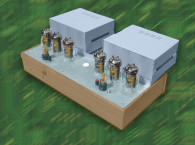
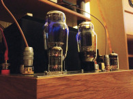
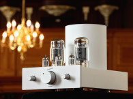
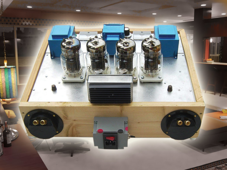
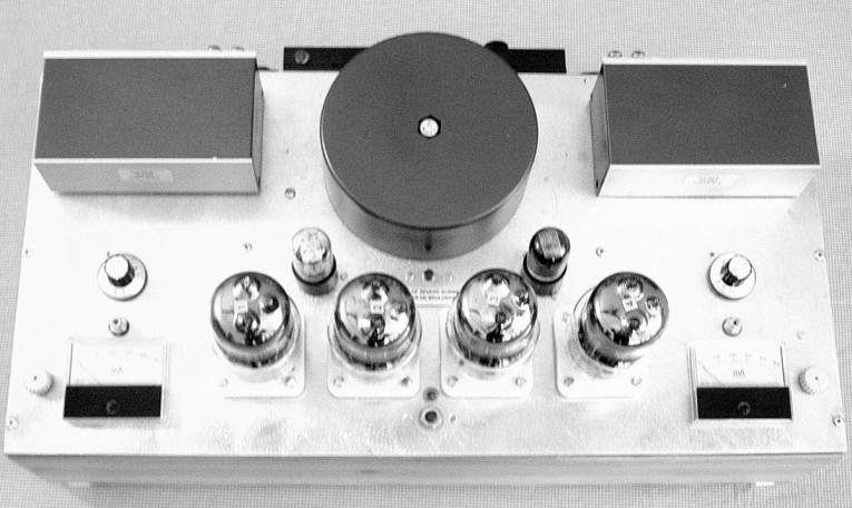
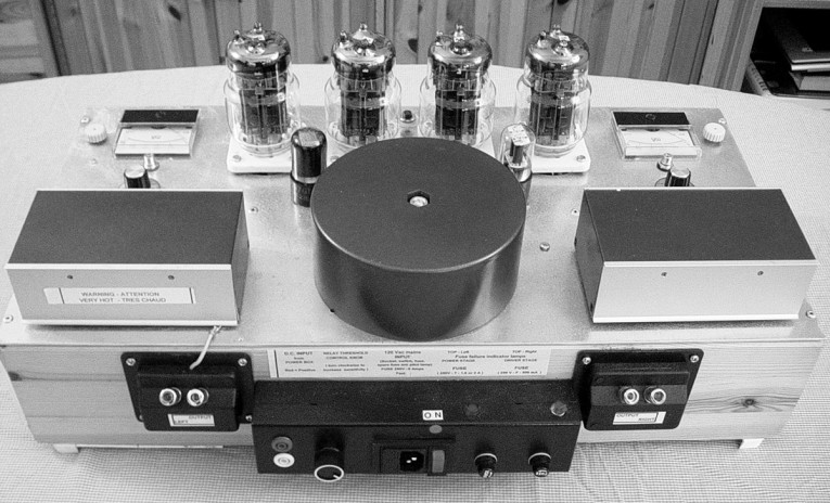
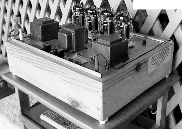
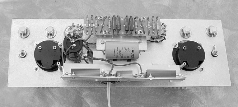
But does it work? Yes, and more than satisfactorily, provided its construction follows certain rules. Besides, it has opened the door to many additional features, as you will see later. I built (after many bench prototypes) three complete amplifiers (Photos 2-5) with the above principles. The results, especially the quality of sound, were quite good. Even after listening to this amp for a long time, it still gives you joy and relaxation.

Opt Behavior
I can assure readers that the result is quite surprisingly good, even concerning the crosstalk between channels4. I mentioned that the output transformer, with its novel layout, works well with a phase inverted signal. Along with co-inventor Giovanni Mariani, head of the R&D department of Graaf, Italy, we considered the alternative of “without phase inversion.” He tended to discard the latter solution, insisting on the fact that, as with a push-pull transformer, the phase inversion condition delivers good power in the bass range and that feeding it with same-phase-swings lets each primary interfere with the opposite one, with the result of reducing the inductance and consequently restraining the range in the lower frequencies. No doubt he is certainly right, but, after some tests, I found that with a good initial primary inductance and a loose coupling factor between the two channels’ windings5, on a suitable magnetic core (UI – C or EI with the middle branch removed), the OPT is still working satisfactorily, for those who appreciate the midrange more than the deep bass6.
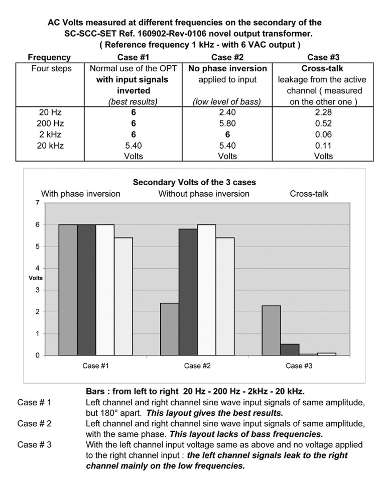
Here are some test results with the OPT modulated by same-phase signals, as well as opposite ones, on the first two amplifiers7:
1. With phase inverted swings, much more bass is heard and measured and the output power is almost the same level as the one obtained with a push-pull circuitry. The high-frequency limit depends essentially on the structure of the primary/secondary windings (tightness of the coupling, number of interleaves, and so on) and of the core material quality.
2. Without phase inversion, the high-frequency range does not change noticeably, but the bass range is less extended (in the OPT the –3B point at the low end shrinks to about 45Hz as opposed to the original 10-11Hz). Therefore, there is a loss of power in the bass frequencies, starting at about 100-120Hz8.
3. In both cases, the leakage between the channels was negligible, in the mid-range and above, and did not affect the stereophonic image. On the other hand, the crosstalk was more intense in the lower frequencies area (Table 1).
Other observations on the results of the tests:
- Case #1 (input signals inverted): The output voltage across the secondaries is flat from below 20Hz to about 20kHz (Note: the slight drop in the high frequencies is due to the inverter network).
- Case #2 (input signals with same phase): There is a heavy drop at the low frequency end.
- Case #3 (crosstalk): Considering that the noticeable interference is located in the bass range, the channel separation — i.e., the crosstalk level — is acceptable. The mid and high frequencies are spared, as stated here:
20Hz = 38% (-8.4dB)
200Hz = 8.6% (-21.3dB)
2000Hz = 1.1% (-39dB)
20000Hz = 1.6% (-35dB)
Placed more than 4m apart, the speaker enclosures reduce the effect of the crosstalk when a bass note is reproduced. Generally speaking, the sound with the SC-SCC output transformer can be defined as “full” or “consistent,” occupying the entire stage without interruption.
Recommendations
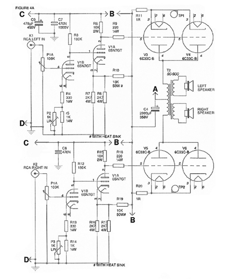
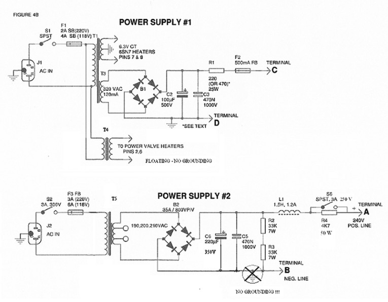
I recommend you first build the driver stage, which should be totally independent from the power stage. From my experience, the schematics of this stage — shown in Fig. 4a, together with its power supply (#1) shown in Fig. 4b — can be considered to represent a universal driver. This driver stage provides for all the necessary conditions to let the power stage do its work — that is, bias supply and transfer of the amplified signal. You will notice that no blocking capacitor is present between the driver and the output stage9.
Consequently, the power stage becomes drastically simplified. Figure 5 shows a suggested layout of the components (see also Photos 7 and 8) of a driver unit under construction for an efficient and trouble-free driver stage, which should also include its dedicated power supply (Fig. 4b).
Before proceeding, first make sure that the driver section works properly. Building the whole amplifier at once can turn into a nightmare, if you make some mistakes here and there. Better to proceed step by step.

Advantages
A completely independent driver stage is easier to build and check for proper operation. Here’s why I referred to this driver as a universal one.
A power stage basically comprises two major, important elements: the power valves and the output transformer. You must size the latter according to the power valves’ characteristics, as far as impedance (a rule of thumb suggests that it be two to four times the internal resistance of the valve — or more, but with a loss of power), as well as the DC idle current and the AC power handling capacity. On the other hand, to operate satisfactorily, the valves’ grids need to be “biased,” generally at a negative level, and receive an AC signal with a large enough swing to produce full power output (normally — and this is called Class A— with a peak amplitude not exceeding the negative bias level).
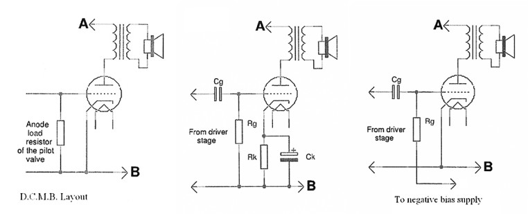
While the task of providing this swing is definitely the driver stage’s responsibility, the negative bias can be provided for in different ways, typically with the self biasing or fixed bias supply systems (Figs. 6-8). In the direct coupling modulated bias layout (DCMB), the bias is supplied by the anode load resistor of the pilot valve located in the driver’s stage. As a consequence, the set of components of the power stages is reduced to the essential ones (valves and output transformers).
The average negative bias for a 6C33C-B set to 80-90V, with a voltage of 220-230, between cathode and anode (k and a), corresponds to an idle current between 200 and 250mA. This value, however, depends a lot on the valve’s conditions (brand new or used valves with different characteristics, and so on). The 300B would require the same bias, but the voltage between k and a should be about 400V, in which case the resulting idle current would be approximately 75-85mA. With the EL34, you have -35V, 350V, 75mA. For the 2A3, the figures are -45V, 240V, 55mA (for other valves, please consult the previous articles in audioXpress or the technical characteristics of the valves published by the manufacturers or in some Internet sites).

Power Handling
During the tests on these amplifiers, I also had the opportunity to vary the idle current while listening to the amplifier, and I noticed that (obviously, I would say now) the sound changed somewhat. I tried the amplifier with different idle plate currents, ranging from 100 to 250mA DC, using the variable resistors (P2 and P3 in Fig. 4a) that adjust the 6C33 valves’ plate consumptions (dissipation) and went from a Pa of 23W (100mA) to over 50W.
I am aware of two effects when the idle current level is increased:
1. a different damping factor (due to the fact that a valve operated at a higher anode current has a lower plate resistance)
2. more bass10, for the same reason. The output power at midrange frequency is not particularly affected, according to the tests I made. You could use these features to reduce the valve’s stress (when the idle current is set at a lower level) if the music is soft without bursting sections, or a high bass content.
Circuit Details
Some measurements (average):
- Frequency range: (at 20W of power output)
a) 40-50Hz to 30kHz at –3dB (without the inverter)
b) 11Hz to 29kHz at -3dB (with the inverter).
- Total harmonic distortion: 1% at 10W, 4% at 20W measured at 1kHz.
Needless to say, the output transformer’s quality is very important if you want to obtain these results. The sources are indicated at the end of the article, but, if you want to build it yourself, the basic details are available. They are intended for private and noncommercial use.
I must state that it is not very easy to build. Anyway, you can contact me at these e-mail addresses for further information: Email 1 or Email 2.
This new kind of compensated audio output transformer for SE amplifiers is quite tolerant and does not require critical calculations. Even the primary impedance (depending on the turns’ ratio as well as on the impedance of the load connected to the secondary) could vary to a certain extent without unacceptable consequences (for the amplifiers described, from 300 to 600Ω). Needless to say, the more accurate the work is, the better the results in terms of frequency range and distortion.
Conclusion
The amplifier’s circuitries described allow for some interesting listening alternatives, such as more or less bass, more or less idle power fed to the output valves (irrespective of the integrated volume control adjustment), and must be considered as an attempt to explore new ways for better listening that would please demanding audiophiles. These features might suggest that they make the amplifier more complicated, but, luckily, once you have found the alternatives that better suit your taste, you can stop playing with the soldering iron, knobs, and connections and listen to the music in your preferred way.
The 6C33C DCMB amplifiers shown in the photos delivered an extremely pleasant sound — precise, “cool” but also explosive (and this includes the higher setting of the idle current level) when required, and “consistent” (sorry, but I could not find a better word to qualify the difference I noticed, compared to a SE amplifier fitted with a pair of output transformers, instead of a common magnetic core one).
You will need to resolve for yourself the question of whether the layout described is single-ended or double-ended?

Footnotes
1. Disregarding the losses, the power transmitted by the primary (VA = volt amperes) is the same in the secondary. Va = Vp × Ip = Vs × Is. Therefore, if you have 100V and 0.1A in the primary winding, the corresponding power is 10VA. If the turns’ ratio primary/secondary is, for instance, 10, you would have 10V at the secondary terminals and the same power available (10V × 1A).
2. This novel OPT has been designed as SC-SCC-SET, meaning: Split core-Stereo Common Circuit–SE Transformer. It’s a novel transformer, patented by Ari Polisois and Giovanni Mariani (Chief Engineer R&D/Graaf/Modena—Italy), INPI Patent# 03 13898. It was presented at the Audio Engineering Society convention held in Paris in May 2006, following the presentation of the first generation of the basic self compensated transformer—INPI patent # 0102457 at the AES convention of May 2005 (Barcelona, Spain).
3. For an extended high-frequency range, a good number of interleaves is recommended: four primary and three secondary would give excellent results.
4. The reason might be the following: In the iron core, two opposed magnetic fields generated by the DC flowing in the primaries fight steadily, tending to cancel each other. Depending on the amplitudes of the left and right channels’ alternating currents, the above balance is upset, but the DC fields dominate the scene, if they are much stronger than the AC ones. However, more likely, the real cause of the situation is the very close coupling between each primary with its secondary, combined with the loose coupling between these two sets (see also note 5). The tighter the coupling primary/secondary and the weaker the coupling between the windings of the two channels, the less crosstalk you have.
5. The loose coupling is improved by the “side flux escapes” that are described in the construction sidebar.
6. I needed to modify the inverter set (the bass boost box, shown in Photo 6) by introducing a bass control. It is simply a pair of variable resistors (5k each) inserted between the RCA inputs (left and right channels) and the primaries of the inverting transformers. At their maximum resistance, the –3dB point at the low frequency end moves from 10Hz to 40Hz.
7. They both use two 6C33C-Bs per channel, with about 25W output.
8. However, with the two paralleled 6C33C-Bs per channel, giving an average internal resistance close to 60Ω, the basses can be heard quite loud (see Menno van der Veen’s book, Modern Audio Amplifiers, chapter 5.5). Because an amplifier without phase-inverter is much simpler and less expensive (fewer valves, passive components, space and time), some of you might prefer alternative # 2. This choice is also justified if you usually listen to CDs recorded with enhanced bass (such as many popular ones), or because your loudspeakers are booming.
Or you could try the following:
a) when a lot of bass is welcome, use a phase splitter transformer (Sowter—UK—references 8920-3603-8584 or model 3B—BassBoostBox from A2Belectronic, as per Photo 6) connected between the CD player’s output and the amplifier’s input RCA sockets, or, alternatively,
b) when disturbed by the excessive bass level, use a direct connection between the CDP and the RCA input sockets of the amplifier, without any phase splitter or inverter.
c) the inverter box with a bass control (see note #5).
Solution b definitively reduces the bass level. It is necessary, in this case, to reverse one of the speakers’ connections, if these are normally set for the high bass level option, in order to have the speakers working with the same phase.
9. This layout, designed as DCMB (direct coupling modulated bias) is described in the article mentioned (aX July 2004) as well as in other sources on the net.
Schematics and comments can be found at the following sites:
www.audiodesignguide.com, or Valve Magazine www.bottlehead.com, or www.Plitron.com, or you simply ask for it by e-mail).
10. Menno van der Veen’s book, Chapter 5.12.
The formula is F_3L = (Z/2πLp) × (β/β+1) where F_3L is the lowest frequency, Z the impedance, Lp the primary inductance, and β = Ri/Z from which it is obvious that Ri (the internal resistance of the valve, inversely proportional to the anode current) plays an important role. aX
Construction Guidelines
Follow these tips when building the basic SC-SCC transformer for the double-ended amplifier circuit of Figs. 4a and 4b
a) Magnetic core.
You need a C core having a cross-section area between 7 and 9cm2 (1.1 and 1.4 in2)
The model reference in Europe is AD32 and has the following dimensions:
Outside length: 169.9mm (6.7″)
Outside width: 97.2mm (3.83″)
Inside length and width (window): 114.3 × 44.4mm (4½ × 1¾″)
Cross sectional area: 25.4 × 31.7 (1 × 1¼″).
b) The horizontal internal dimension of the two bobbins (left and right channel) on which the primaries and the secondaries are wound must be larger by 4 or 5mm, because it will receive six layers of a magnetic band 2cm wide (visible on the sides in Photo 9).
c) The suggested layers of the primary and secondary windings are listed below.
The total number of turns of the primaries must be as close as possible to the stated ones.
1. Close to the iron: 145 turns of 0.5mm enameled wire followed by a second layer with the same number of turns. These two layers (totaling 290 turns) must be separated by a thin sheet of insulation paper. The turns must be wound close to each other and must not overlap.
Note: the inward wire will be connected to the anode; the outgoing will be soldered to the inward wire of the next primary turns layer.
2. Insulation: one presspahn sheet wrapped by an adhesive polyester film (such as the 3M 1350F).
3. One layer of secondary wire 1.6mm diameter (45-46 turns).
4. Same insulation as #2.
5. Another pair of primary layers as #1.
6. Same insulation as #2.
7. A second layer of secondary wire as #3.
8. Same insulation as #2.
9. Another pair of primary layers as #1.
Total primary turns = 145 × 2 × 3 = 870, secondary = 46 × 2 = 92
d) The turns ratio will then be approximately 9.4, meaning a primary impedance of 700Ω on a load impedance of 8Ω (9.42 × 8).
e) The suggested wire diameter is suitable for a maximum idle direct current of 500-550mA, as opposed to the suggested total current of 460mA (230mA per valve).
f) Take care to properly insulate the layers, as well as the outgoing wires (with sleeves), because the potential difference between primary and secondary (as well as primary and ground) exceeds 850V (DC plus AC). Conservatively, I recommend a 1.5kV insulation.
g) You must solder the primary layers in series. As mentioned, the first inward wire will be connected to the anode and the last outgoing wire (the one that comes out from the external primary layer) to the B+. Due to the primary layers being a pair (left to right and then right to left, or vice versa), all their wire terminals will be on the same side. The secondary wires will also be soldered in series, but, in this case, the intermediate terminals to be soldered together will be on opposite sides, unless the second layer is wound from right to left (if the first one was wound from left to right). As you can imagine, custom building the output transformer requires much attention and patience.
This article was originally published in audioXpress, February 2008