Audio circuits require a DC voltage to operate, so all devices have either a battery or a power supply that converts the AC voltage from the wall outlet to a DC voltage needed by the circuits. If you power an audio circuit from AC, the 60 Hz (or 50 Hz) mains frequency will modulate the audio and appear at the output as hum.
Solid-state devices operate on low voltages, typically 15 V or less, while tube circuits require hundreds of volts. The internal input and output points of many circuits are not centered at 0 VDC, so coupling capacitors are used between stages. This is especially needed with tube devices, but also with many solid-state circuits that use discrete transistors instead of op-amps. So if the at-rest DC voltage at the output of one internal stage is 5 V, but only 2 V at the input to the next stage, a coupling capacitor is placed in the signal path to allow audio to pass without upsetting the DC voltage difference.
A capacitor is constructed from two metal plates in close proximity but not quite touching. The larger the plate surfaces, and the closer the plates are to each other, the greater the capacitance will be. One common construction uses parallel strips of metal foil, with thin plastic insulation between the strips. The assembly is rolled up to save space, then dunked into goo that hardens. Since the metal plates aren’t electrically connected, DC can’t get through.
However, current can flow through a capacitor when the applied voltage changes. Although there’s no physical connection through a capacitor, a light bulb attached to a battery through a capacitor will flash briefly when first connected.
Therefore, a capacitor passes AC because the voltage keeps changing. And high frequencies get through more easily than low frequencies because the voltage changes more quickly. You can think of a capacitor as a frequency-selective resistor, and, in fact, that’s exactly what it is! Sending audio in series through a capacitor creates a high-pass filter because less signal passes through at low frequencies. On the other hand, wiring a capacitor as a short circuit across the audio signal creates a low-pass filter with higher frequencies reduced in level. The cut-off frequency of these filters depends on the capacitor’s value — its capacitance — along with the destination load resistance.
One problem with capacitors is they can distort the audio passing through them. But this happens only when the signal level changes through the capacitor. At very high frequencies, all of the audio gets through; and at very low frequencies, none of the audio gets through. Distortion occurs only when some of the audio passes and some is blocked.
So it’s important for capacitors in the signal path to have low distortion, but this applies mostly for equalizers and other filters where the capacitor’s loss occurs within the audible pass-band. Coupling capacitors in series between stages of an audio circuit generally have a large enough value to roll off starting below 20 Hz. Since little audio voltage is lost across a coupling capacitor at the higher audible frequencies, in theory their distortion should not be a factor. This is exactly what I set out to prove or disprove with my tests.
The main contributor to capacitor distortion is its voltage coefficient. This is a measure of how much the capacitance changes as the applied voltage varies. Ideally, a capacitor should have the same amount of capacitance no matter how much voltage is present across its terminals.
Another contributor to capacitor distortion is its dielectric absorption, which is a “memory” effect. After discharging a capacitor fully, some DC voltage reappears soon after because part of the charge was stored within the capacitor’s dielectric — the technical term for the insulating material between the metal plates.
Capacitor distortion greatly varies from very low with Mylar, polystyrene, and mica types to unacceptably high with some electrolytics, and even higher for ceramic types. Here, the capacitor “type” identifies its dielectric material. High-density ceramic capacitors that pack a lot of capacitance into a small physical size are even worse, and also suffer from the piezoelectric effect. This generates an audible noise when the capacitor is tapped or subjected to vibration.
Measuring Capacitor Distortion
As part of my work as an acoustic consultant, I’ve come to rely on the Room EQ Wizard (REW) software. This “donationware” program measures every aspect of room acoustics (e.g., frequency response, reverb decay times, and much more). It also includes a distortion analyzer to measure the distortion of loudspeakers. Coupled with a high-quality sound card (e.g., the Focusrite Scarlett 8i6), REW can be used to measure the distortion of passive components (e.g., capacitors and transformers) and even active devices such as equalizers and preamps.
There are other audio measuring programs such as the popular RightMark Audio Analyzer, which is meant for exactly this sort of testing. But I already have REW and know it very well. Measuring capacitor distortion is more complicated than simply sending audio through the component being tested. Capacitors being measured must “drive” a resistor load connected to ground to force a voltage drop across the capacitor, in order to emulate how they’re used in audio circuits. And testing different value capacitors requires changing the load resistance to keep the cut-off frequency within the audible band. This way we can see how the distortion varies both below and above the cutoff frequency. A 22 μF capacitor driving a 1,000 Ω load has a low-frequency cut-off at 7 Hz, which is too low for REW to display. Further, testing polarized capacitors requires a DC bias voltage large enough to ensure the polarity is never reversed by audio present across the cap. The largest test signals I used were REW’s swept sine waves at slightly less than 2.2 VPP, so a 1.5 V AA battery was sufficient for my tester. That is, the reverse portion of the sine wave polarity was 1.1 V or less, leaving a 0.4 V safety margin.
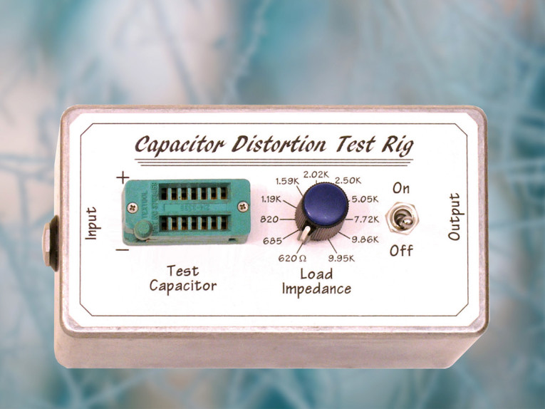
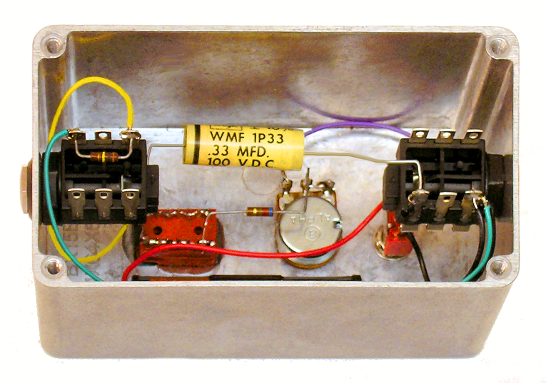
Photo 1 shows the front panel of my device, which is simply card stock glued to an aluminum project box with 3M spray photo mount. I used a Zero Insertion Force (ZIF) socket for the capacitors being tested because it’s a lot easier to insert and remove components than with a normal IC socket. Plus, I already had it. This socket accommodates both thick and thin wires, which is needed with the range of capacitor values I tested.
The capacitor being tested and the Load Impedance potentiometer plus a 620 Ω “limit” resistor form a high-pass filter, with the potentiometer setting the low end cut-off frequency. The On/Off switch adds the battery when needed to bias polarized capacitors, or grounds the resistors directly.
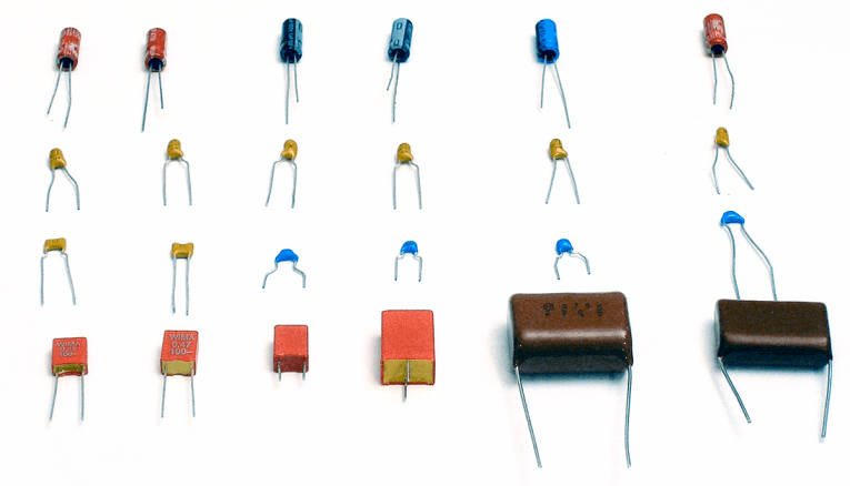
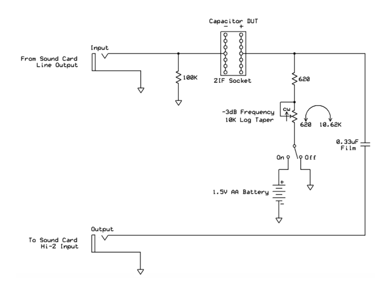
Figure 1 shows the tester schematic. Photo 2 shows its internal wiring. As you can see, it’s a very simple device! In use, the sound card’s Line level output goes to the tester’s input, and the tester’s output goes back into the sound card’s Instrument level input. My sound card’s line output has a very low impedance and can drive a load less than 600 Ω without increasing its own already-low distortion.
I actually tested this using a 1 kΩ trim pot. The distortion stayed at the same low value to below 500 Ω, so 620 Ω is a safe lower limit. The inputs to my Focusrite sound card can be switched between line level with a claimed input impedance greater than 10 kΩ (I measured it as 24 kΩ), or set for “Instruments” that output a lower signal level and require a much higher input impedance. Passive electric guitars and basses need to drive an input that’s at least 1M, and I measured this input at 2.9M, which is very high. The tester needs its own output coupling capacitor to block the 1.5 VDC when the battery is engaged. I measured the distortion of several high-quality film capacitors I already had in my parts bin, and none increased the sound card’s own low distortion. So I chose the 0.33 μF Cornell Dubilier WMF Polyester Film capacitor shown in Photo 2 because it’s old school and looks cool.
I used a 10 kΩ audio taper potentiometer to vary the load impedance, and the schematic shows the expected range of values from 620 Ω through 10.62 kΩ. But when I calibrated the panel labeling by measuring the resistance at each line marking, I discovered that the potentiometer is actually 9.33 kΩ. So the panel labels are correct. The load impedance potentiometer allows keeping the roll-off frequency within range to see distortion above and below that frequency. I used the terrific Electronics Assistant freeware calculator from the Electronics2000 website to help determine the best values.
As I previously mentioned, the tester includes a 1.5 V AA battery when needed to bias polarized capacitors to ensure that their plus terminal is always more positive than the minus side. Without this bias, the capacitor would add more distortion than normal. I didn’t apply this voltage when testing the ceramic and film capacitors, though I tried that earlier and it didn’t make any difference. I also measured the distortion of a large value film capacitor driving the worst case 620 Ω load with and without the battery, and the response and distortion were identical. So that proves the battery presents a suitably low impedance at audible frequencies. However, this applies only for a fresh battery — as a battery drains its impedance rises. Since minimal current is needed to charge the relatively small capacitors this device tests, the battery in my tester should remain usable for years.
Measuring Distortion
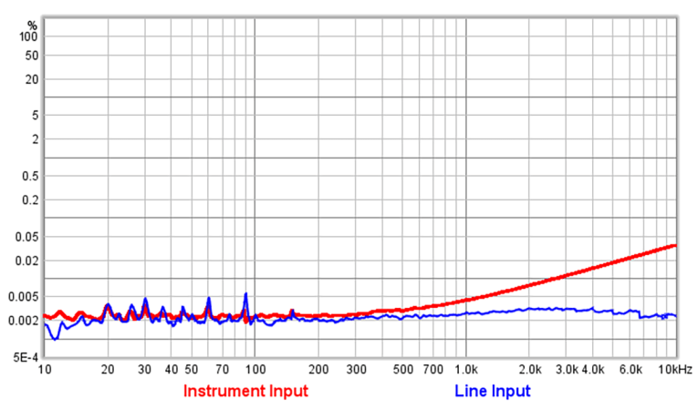
Before I could measure the distortion of various capacitor types and values, I needed to confirm my sound card’s own distortion. This is easy to do using a “loop-back” connection whereby the sound card’s output is connected back to its own input. Figure 2 shows the distortion measured for a direct connection using both inputs. Focusrite specs this sound card at 0.001% total harmonic distortion plus noise (THD+N) for the outputs, and 0.004% THD+N at 1 kHz for the Instrument input I used. As you can see, the distortion is much lower at mid and high frequencies with the Line input than the Instrument input, and the Instrument input’s distortion rises above 1 kHz.
Both measurements in Figure 2 were made with the sound card outputting –5 dBFS. Minimum gain for the Instrument input is 13 dB, so I set the same amount of preamp gain when I switched the input to line level. The capacitor distortion measurements that follow used the high impedance Instrument input to avoid interacting with my tester’s 10 kΩ load impedance pot and 0.33 μF output capacitor. You can see little blips at 30 Hz multiples where the distortion at very low frequencies seems to increase, but that’s most likely due to a small amount of hum being picked up.
For my tests I bought one capacitor each in six values of four types (see Photo 3). The four types I tested were film, aluminum “can” electrolytic, tantalum electrolytic, and ceramic. The six values tested were 0.22 μF, 0.47 μF, 1 μF, 2.2 μF, 4.7 μF, and 6.8 μF, though the figures that follow show only three of those values because all the values measured similarly. The entire set of 24 capacitors cost less than $10, though I feel sorry for the poor employee at Mouser Electronics who had to bag and label all of these single parts!
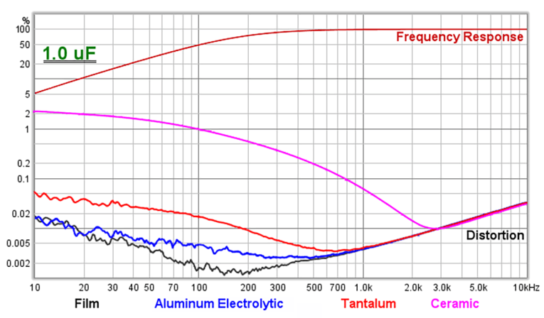
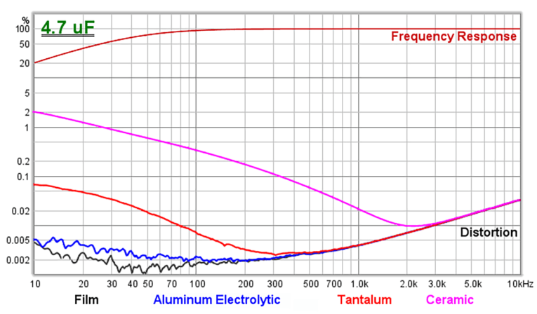
It wasn’t practical to test very large value capacitors because that would put their low-frequency –3 dB cut-off at too low a frequency, and these tests need to show what happens well below that cut-off. To test a 100 μF capacitor at 100 Hz would require a load resistor of 16 Ω, which is much too low for my sound card to drive without adding distortion of its own. So I tested at 500 Hz for the smaller capacitors, and lowered the frequency for the larger value capacitors. Since I couldn’t go below 620 Ω, tests for the larger value capacitors start rolling off at lower frequencies. But the frequencies are still high enough to see how the distortion rises below cut-off.
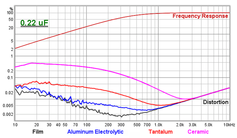
For these distortion tests REW was set to output a level of –5 dBFS through my sound card. This applied the maximum practical voltage across the capacitors, but without distorting the sound card’s high impedance Instrument input that was set at its minimum gain. For my Focusrite 8i6 sound card, –5 dBFS equates to an output level of 0 dBu, or 0.775 V RMS (2.19 VPP). Figures 3–5 show the distortion of three values for all four capacitor types.
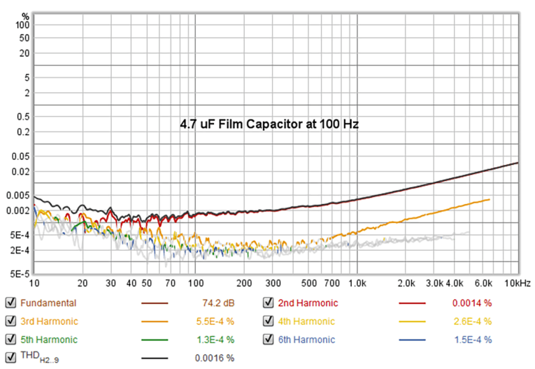
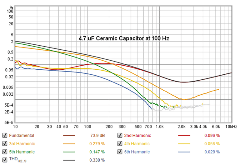
For clarity, the distortion comparisons in Figures 3–5 show only the total distortion amounts, but REW can also display the level of individual harmonics. Figure 6 and Figure 7 show the total distortion plus all of the individual harmonics up to the sixth for 4.7 μF film and ceramic capacitors. For the ceramic capacitor you can see that the third and fifth harmonics dominate, but for film types the second harmonic is the largest contributor. The numbers at the bottom are for the distortion amounts at 100 Hz.
Since capacitor distortion varies with frequency, the numbers REW displays follow the current cursor location. So I put the cursor at 100 Hz when I exported these images. To show the worst case for ceramic capacitors, the types I tested were either Z5U or X5R. Besides having high distortion, they’re also microphonic due to using a piezoelectric dielectric that packs more capacitance into a very small physical size. NP0 and C0G ceramic capacitors are much better, but still nothing like film or polystyrene capacitors. For the piezo tests, I connected one each of the four capacitor types to the input of my Fender SideKick guitar amplifier. Guitar amps have a very high input impedance, which is needed when receiving audio from a piezo device (e.g., a contact microphone). I put my Zoom H2 portable recorder 6” in front of the amplifier’s speaker and cranked all three volume and gain knobs fully. Only the ceramic capacitor made noise when I tapped it with a small metal pliers. You can download the audio file listed in our Project Files on the audioXpress website to hear this noise, though there’s a lot of amplifier hiss since the volume was raised to maximum.
As stated at the beginning of this article, my goal was to determine whether or not distortion is a problem for coupling capacitors at audible frequencies above 20 Hz. Looking at the measurements in Figures 3–5, it’s clear that for all of the capacitor types other than ceramic, distortion is indeed a problem only at frequencies near and below their low-frequency roll-off. For higher frequencies even inexpensive aluminum electrolytic capacitors have distortion close to the low residual distortion of the sound card itself. Though it’s equally clear from my tests that cheap ceramic capacitors should never be used in any audio signal path!
While preparing this article, I learned that it’s very difficult to measure the tiny amounts of distortion in modern sound cards and film capacitors. I had to use a longer sweep time and multiple sweep repetitions in REW to increase the resolution over the program’s default settings for measuring rooms. To get the highest resolution possible in REW takes four minutes for each sweep to complete! But even when a capacitor has slightly more distortion than the sound card itself, in practice anything less than 0.1% is mostly benign since at that point the distortion artifacts are 60 dB below the music. Of course, many audio devices employ more than one coupling capacitor, and all distortion accumulates. So it’s best if each stage has even less distortion than is audible.
Beyond Capacitors
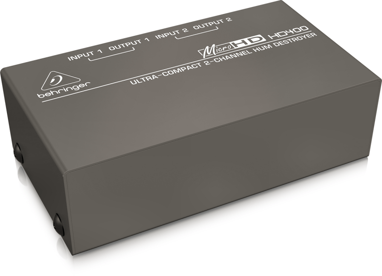
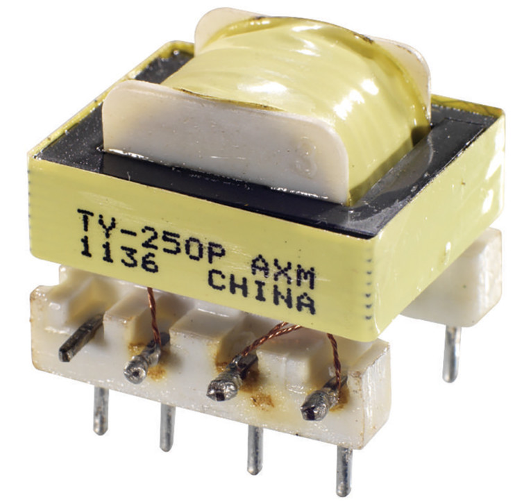
REW can also measure the distortion of transformers and even entire circuits, without needing my capacitor test device. So for fun I measured two transformers I already had — the Behringer HD400 shown in Photo 4 and the bare (uncased) Triad TY-250P that is shown in Photo 5 and costs about $6. Unlike the capacitor tests that required driving the high impedance Instrument input of my sound card, I used the Line level input for the transformer and equalizer measurements that follow.
I measured the HD400 at several signal levels, and the results in Figure 8 show differences not only in distortion but also frequency response at low frequencies. In order to show both frequency response and distortion for all three levels on the same graph, I set the vertical scale at left to display dB SPL instead of distortion percentages as in Figures 3–5. Every 20 dB level difference is a factor of 10, so the distortion is the difference in decibels between the Frequency Response line at top and the Distortion line below. For example, at 30 Hz the distortion of the largest 0 dBu signal spans two 20 dB marker lines, and so is about 1%.
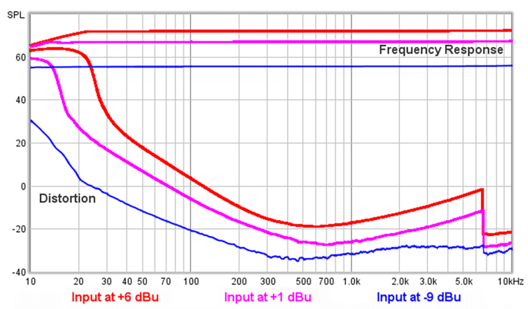
I tested the HD400 transformer as it’s intended to be used: fed from the low impedance balanced Line output of my sound card, then sent back into the 24 kΩ Line input. Since I used the balanced output from my sound card having both plus and minus signals, REW’s –5 dBFS output became 6 dB higher into the transformer than when I used the unbalanced (single conductor) output for the capacitor tests. The actual levels are shown as dBu in Figure 8.
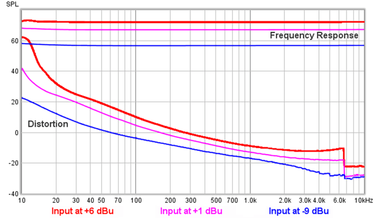
I tested the Triad TY-250P, shown in Photo 5, in exactly the same way as the Behringer, from the balanced output of my sound card at the same three voltage levels. The results in Figure 9 show that this transformer is similar to the Behringer, but with more distortion at low frequencies and less at high frequencies. Note that for both transformers, the dominant distortion component is the third harmonic. This is why the distortion drops off suddenly around 7 kHz, which is one-third the upper frequency limit of the 44.1 kHz sample rate I used for all my tests. The distortion of these inexpensive transformers isn‘t terrible, and at the typically low consumer voltage levels they could be considered “high fidelity” above 20 Hz or 30 Hz, anyway. By contrast, a high-quality audio transformer such as the Jensen Iso-Max CI-1RR has much better specs, including distortion at 20 Hz less than 0.04% at levels much higher than I used to measure these cheap transformers. But at $130, it’s a lot more expensive. With audio transformers, you get what you pay for!
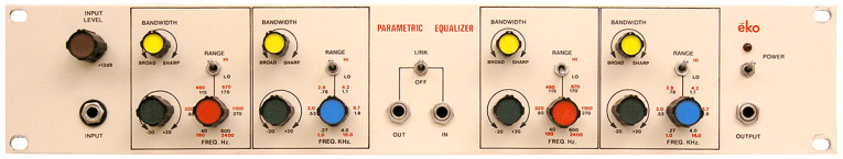
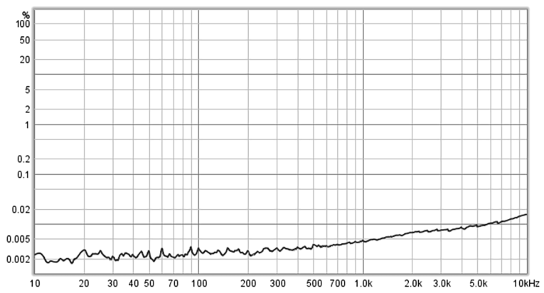
Finally, I measured the distortion of the parametric equalizer in Photo 6. I built four of these in the 1970s for my professional recording studio, and an article describing the circuit along with the schematics are on my website. Figure 10 shows the measured distortion — I was pleasantly surprised at how well this ancient unit performed in these tests!
The last point I’ll mention is that REW doesn’t measure intermodulation distortion (IMD), which is more damaging than the harmonic distortion I measured for this article. Where harmonic distortion adds musically related overtones to single frequencies, IMD creates sum and difference tones related to source frequency pairs. Worse, the added frequencies are not necessarily related to the musical notes that created them. So IMD is typically more audible and more objectionable than harmonic distortion.
But the two distortion types go hand in hand, and they’re always present together. So having low harmonic distortion also ensures low IMD. Finally, I want to mention Doug Self’s excellent book Small Signal Audio Design, now in its second edition, as the source of my interest in capacitor distortion. This book is a must-read for advanced audio hobbyists, and even professional circuit designers will find much of value. Another excellent resource that goes into great detail is Cyril Bateman’s “Capacitor Sound” articles. aX
This article was originally published in audioXpress, May 2020.
Project Files
To download additional the Capacitor Piezo test.mp3, visit audioxpress Supplementary Material page
Resources
C. Bateman articles, Linear Audio, https://linearaudio.nl/cyril-batemans-capacitor-sound-articles
Electronics 2000, www.electronics2000.co.uk/download.php#assistant
Jensen Transformers, www.jensen-transformers.com/product/ci-1rr
RightMark Audio Analyzer, http://audio.rightmark.org/products/rmaa.shtml
Room EQ Wizard, www.roomeqwizard.com
D. Self, “Small Signal Audio Design,” 2nd Edition, Focal Press, August 2014,
www.amazon.com/Small-Signal-Audio-Design-Douglas/dp/0415709733
E. Winer, “Spectrum Analyzer and Equalizer Designs,”
http://ethanwiner.com/spectrum.html
Ethan Winer’s own website | ethanwiner.com
RealTraps | realtraps.com