Inverse Horn Loudspeakers
Patent Number: 9,344,783
Inventors: Philip R. Clements; (Tempe, AZ), Boaz Shalev; (Needham, MA), James Joseph Croft, III; (Bellevue, WA)
Applicant: Philip R. Clements; (Tempe, AZ), Boaz Shalev; (Needham, MA), James Joseph Croft, III; (Bellevue, WA)
Filed: June 12, 2014
Class: H04R 1/02 (20130101)
Granted: May 17, 2016
Number of Claims: 24
Number of Drawings: 22
Abstract from Patent
In a low-frequency transducer system a multi-compression chamber, an inverse horn structure is employed in combination with a resonance-distortion filter chamber. The filter chamber effectively expands the effective enclosure volume at low frequencies and connected to one of the compression chambers filter parasitic resonances and distortion and allowing the system to more efficiently reproduce low frequencies while being able to use smaller diameter transducers and maintaining good system sensitivity. Compression chambers are organized for constant or continuous compression on a section-by-section basis throughout the inverse horn system.
Independent Claims
1. A loudspeaker system, comprising: at least one first electro-acoustical transducer mounted in a transducer opening on the loudspeaker enclosure, the first electro-acoustical transducer comprising a moveable diaphragm for converting an electrical input signal into a corresponding acoustic output having pressure; at least one inverse horn structure, comprising: at least one second electro-acoustical transducer mounted in a transducer opening on the horn enclosure, the second electro-acoustical transducer comprising a moveable diaphragm for converting an electrical input signal into a corresponding acoustic output having a pressure; a first compression chamber enclosing a rear side of the second transducer, a first internal volume that receives the acoustic output from the diaphragm, and a first exit comprising a first cross-sectional area; a second compression chamber comprising a second entrance and a second exit comprising a second cross-sectional area, the second entrance directly acoustically connected to the first exit of the first compression chamber, and the second cross-sectional area being smaller than or equal to the first cross-sectional area; a third compression chamber comprising a third entrance and a third exit comprising a third cross-sectional area, the third entrance directly acoustically connected to the second exit of the second compression chamber, the third cross-sectional area being smaller than or equal to the second cross-sectional area; wherein at least one of the compression chambers has a substantially constant cross-sectional area from its entrance to its exit, and wherein any compression chambers placed immediately before or after a compression chamber with substantially constant cross-sectional area has a reduction in cross-sectional area from its entrance to its exit; and a last exit acoustically coupled to an exit of one of the compression chambers, the last exit acoustically coupled to an external environment.
12. A loudspeaker system, comprising: at least one electro-acoustical transducer mounted in a transducer opening on the loudspeaker enclosure, the electro-acoustical transducer comprising a moveable diaphragm for converting an electrical input signal into a corresponding acoustic output having pressure; at least one inverse horn structure, comprising: at least one electro-acoustical transducer mounted in a transducer opening on the horn enclosure, the electro-acoustical transducer comprising a moveable diaphragm for converting an electrical input signal into a corresponding acoustic output having a pressure; a first compression chamber comprising the transducer, a first internal volume that receives the acoustic output from the diaphragm, and a first exit comprising a first cross-sectional area; a second compression chamber comprising a second entrance and a second exit comprising a second cross-sectional area, the second entrance directly acoustically connected to the first exit of the first compression chamber, wherein the second compression chamber tapers from the second entrance to the second exit; a third compression chamber comprising a third entrance and a third exit comprising a third cross-sectional area, the third entrance directly acoustically connected to the second exit of the second compression chamber, wherein the third compression chamber has a substantially constant cross-sectional area from the third entrance to the third exit; and a last exit acoustically coupled to an exit of one of the compression chambers, the last exit acoustically coupled to an external environment.

Reviewer Comments
This is the third patent granted on Atlantic Technology’s low-frequency system known by the trademark name H-PAS (High Pressure Acceleration System). The primary embodiments of this system are the creation of Phil Clements, who developed a similar system in the early 1970s, disclosed in US 4,373,606.
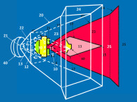
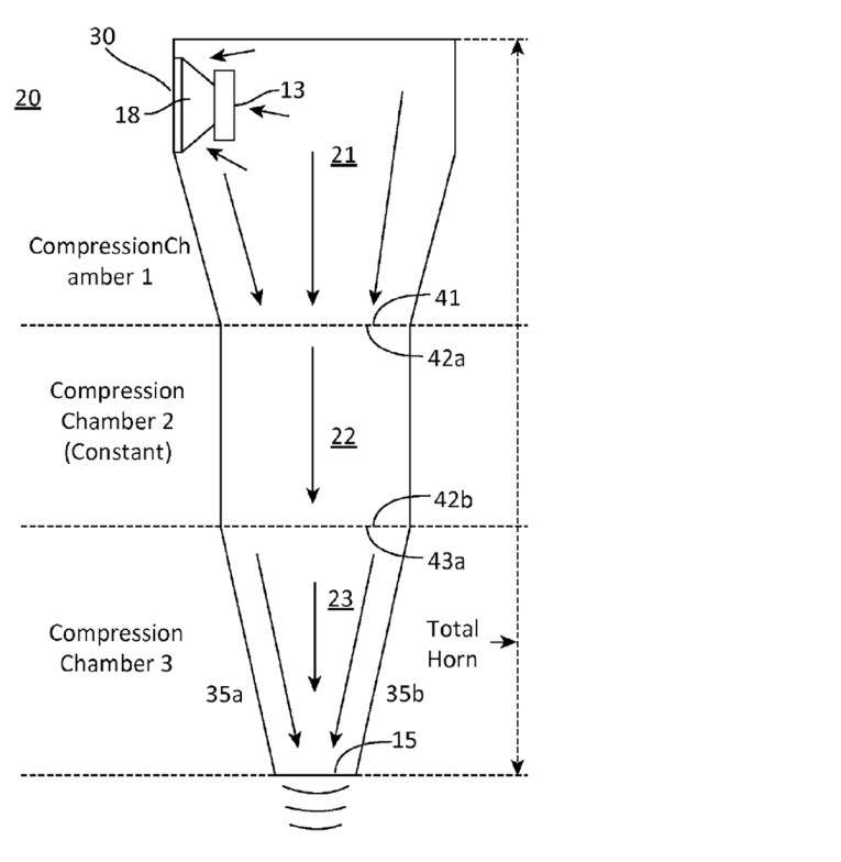
Disclosed is a form of low-frequency “inverse-horn” waveguide with at least three sub-chambers within the enclosure. The waveguide includes a first, and largest, sub-chamber receiving the rear-wave acoustic output of woofer transducer. The first sub-chamber has an exit opening at the opposite end of the chamber from the woofer, and the chamber is formed to have a reduced cross-sectional area from the woofer to the sub-chamber exit opening, which exits into a second sub-chamber. The second sub-chamber volume is smaller than the first sub-chamber and the second sub-chamber cross-sectional area is either constant or reduced from its entrance to its exit opening, which is the entrance to at least a third sub-chamber. The third sub-chamber is smaller than the second sub-chamber, has a constant or decreasing cross-sectional area from entrance to its exit opening. In the basic three sub-chamber embodiment, the final exit opening has an additional structure to create a final, positive flare termination of the waveguide to the external environment to minimize turbulence and audible chuffing.
Other embodiments have four or more sub-chambers with each successive sub-chamber having a constant or reduced cross-sectional area from entrance to exit. As presented by Clements, the waveguide operates as a form of “inverse horn” with the sub-chambers designed to achieve substantially constant, or continuous, compression from the input to the output of the waveguide.
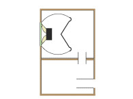
A key additional, but optional, aspect of the system is a Helmholtz side chamber with a singular opening coupled into one of the compression chambers. In most embodiments, the Helmholtz chamber is coupled to either the second or third compression chamber.
In the parlance of the inventor, the Helmholtz chamber is called out as a “Filter-chamber” because it is most often tuned to a frequency at or near the first quarter wave resonance of the inverse horn waveguide.
The Helmholtz ‘filter-chamber’ serves at least two primary purposes. First, it operates as an acoustic filter for absorbing a predetermined frequency or band of frequencies transmitted through the inverse horn waveguide, to reduce distortion or parasitic resonant output. Second, below the resonant tuning frequency of the Helmholtz chamber, the volume of the chamber transitions to being coupled to the volume of the first compression chamber, to function as one summed, large chamber volume at the lowest operating range of the system, increasing the acoustic output of the system at the fundamental tuning frequency.
Other embodiments of the system can include two or more of the Helmholtz filter chambers, to filter different bands of frequencies, and/or create multiple system tunings. Additional embodiments can also incorporate dual inverse horns with separate exits, and in some cases, multiple Helmholtz filter chambers, with at least one dedicated to each inverse horn.
Another embodiment set includes implementing one or more elongated positive flare horns at the exit of the single or dual inverse horn waveguide, which can change the acoustic characteristics of the waveguide such that it operates as a substantially full range output, extending up to 2 kHz or higher.
The licensors of the technology, Atlantic Technology, claim reduced transducer excursion at and near the fundamental tuning frequency (FB), allowing greater linear output for a given driver area (SD) and XMAX, as compared to a standard bass reflex enclosure system of the same size.
While the system superficially appears similar to a transmission line, with a Helmholtz side chamber, the length of the “inverse-horn” waveguide is not long enough to establish a quarter wave column resonance at the fundamental tuning frequency (FB), and in actuality system FB corresponds more closely to a specialized type of Helmholtz Bass Reflex device. As this system architecture evolves it will be interesting to see what its fully realized potential turns out to be.
In the interest of full disclosure, this reviewer has consulted for Atlantic Technology to develop the claims and additional specification for the H-PAS patents along with creating additional embodiments incorporated into the most recent patent. VC
This article was originally published in Voice Coil, September 2016.