Head-Related Transfer Function Equalization and Transducer Aiming of Stereo Dimensional Array (SDA) Loudspeakers
Patent/Publication Number: US20180317034A1
Inventors: Scott Orth (Baltimore, MD); Stuart W. Lumsden (Baltimore, MD)
Assignee: Polk Audio, LLC (Vista, CA)
Filed: April 27, 2018
Current CPC Class: H04S 1/002 20130101
Granted/Published: November 1, 2018
Number of Claims: 15
Number of Drawings: 10
Abstract from Patent
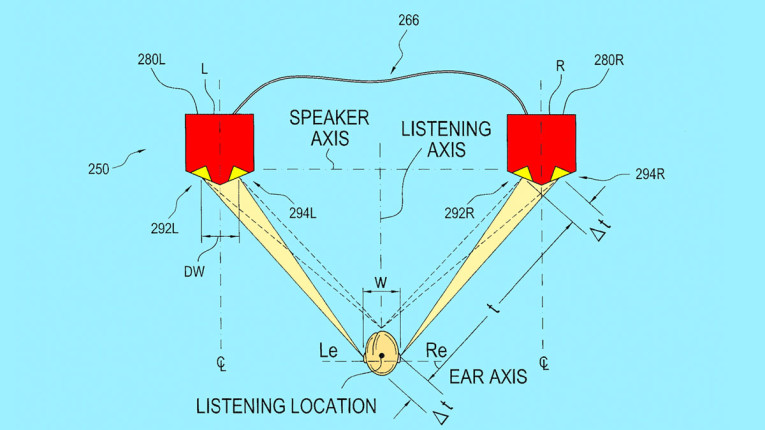
An enhanced Stereo Dimensional Array (“SDA”) Loudspeaker System 250, preferably including a mirror image pair of loudspeaker enclosures 280L and 280R configurable by a user or installer as a left-channel SDA loudspeaker and a right channel SDA loudspeaker uses a novel driver array aiming configuration and an enhanced Head Shadow filter SDA signal processing system and method to achieve a surprisingly effective psycho-acoustically expanded image breadth by inter-aural crosstalk cancellation. The signal processing system and method provide an enhanced method for cancellation of apparent sources of inter-aural crosstalk, as compared to the commonly owned Polk SDA™ (Prior art) method.
Independent Claims
1. A sound reproduction system having a left channel output and a right channel output, apparatus for reproducing sound having an expanded and more stable acoustic field and acoustic image, comprising: (a) a first loudspeaker system enclosure or tower 280L disposed in a first loudspeaker system enclosure location spaced from a listening location, the listening location being a place in a space for accommodating a listener’s head having a right ear location and a left ear location spaced along an ear axis, said first loudspeaker system enclosure having a multi-faceted or multi-planar front baffle surface comprising a first front baffle surface or facet which is angled rearward to recede at a selected (e.g., 10° to 30°, preferably 15°) angle from a vertical plane aligned with the speaker axis on the left side, and a second front baffle surface or facet which is angled rearward to recede at a selected (e.g., 15°) angle from a vertical plane aligned with the speaker axis on the right side, where the first and second baffle surfaces define loudspeaker driver supporting and aiming structures aligned along substantially vertical planes; (b) wherein the first baffle facet carries and aims a first midrange driver having a midrange driver acoustic center and a first tweeter driver having a tweeter driver acoustic center which is preferably substantially vertically aligned with said first midrange driver acoustic center; (c) wherein the second baffle facet carries and aims a second midrange driver and a second tweeter, wherein said second midrange driver has its acoustic center spaced laterally from said first midrange driver by a selected distance D.sub.W (e.g., about 6” to 6.5”), and wherein said second tweeter driver has a tweeter driver acoustic center which is preferably substantially vertically aligned with said second midrange driver acoustic center and spaced laterally from said first tweeter driver by said selected distance D.sub.W (e.g., about6” to 6.5”); (d) said first loudspeaker system enclosure or tower 280L having external terminals for Main (+) and (-) signal inputs, and an SDA signal input/output terminal; and (e) first enclosure signal processing circuitry including a crossover with input terminals for said Main (+) connection, said main (-) connection and said SDA In connection and said SDA Out connection, wherein said crossover is configured to generate (i) a “main” tweeter signal (ii) a “main” midrange signal, (iii) a “Head Shadow Filter” compensated SDA dimensional effect tweeter signal, and a “Head Shadow Filter” compensated SDA dimensional effect midrange signal; (f) wherein said signal processing circuitry communicates said SDA dimensional effect tweeter signal and said SDA dimensional effect midrange signal to an SDA dimensional effect radiating array including said first tweeter and said first midrange which are aimed by said first front baffle away from the listening position.
6. In a stereophonic sound reproduction system having a left channel output and a right channel output, an improved apparatus for reproducing sound having a realistic ambient field and a larger, more stable acoustic image, comprising: a right main speaker and a left main speaker disposed respectively at right and left main speaker locations spaced apart along a speaker axis, with a listening location located generally along a listening axis perpendicular to the speaker axis and intersecting the speaker axis at a point midway between the right and left main speaker locations; means coupling the right and left channel outputs, respectively, to said right and left main speakers; a right sub-speaker positioned on the speaker axis at a right sub-speaker location spaced a predetermined distance from the right main speaker location and further from the listening axis than said right main speaker location; a left sub-speaker positioned on the speaker axis at a left sub-speaker location spaced a predetermined distance from the right main speaker location and further from the listening axis than said left main speaker location; means connected to the right and left channel outputs for developing a left channel minus right channel signal and a right channel minus left channel signal; means coupling said left channel minus right channel signal to said left sub-speaker and said right channel minus left channel signal to said right sub-speaker; whereby sound reproduced by said apparatus as perceived by a listener located generally along the listening axis has a realistic acoustic field and enhanced acoustic image; the improvement comprising: said left main speaker is aimed toward the listening position at a selected main driver aiming angle from a line parallel to said listening axis, said selected main driver aiming angle being between 10° and 30° and wherein said left sub speaker is aimed away from the listening position at a selected sub driver aiming angle from a line parallel to said listening axis which is substantially equal in magnitude to said main driver aiming angle.
Reviewer Comments
One of the most significant developments in multi-channel reproduction, on a formal basis, was revealed in the 1930s as Alan Blumlein defined a new recording and playback system for loudspeakers that was the basis for much of the work going forward. The original ideas were covered in Great Britain Patent 394,325, “Improvements in and relating to Sound-transmission, Sound-recording, and Sound-reproducing Systems,” by Alan Dower Blumlein, June 14, 1933, assigned to Musical Industries, Ltd.
With the long-play albums as the standardized recording delivery format eventually coming to pass in the late 1950s, stereo was finally realized as a popular commercial format. As impressive as the two-channel stereo was, compared to the standard, single loudspeaker mono reproduction of the day, it was also immediately clear to experts at that time that stereo, when reproduced in a smaller, second venue listening room, was still a fundamentally limited format. Among the many shortcomings recognized at the time, was that of the entire sound field being contained between the two loudspeakers, and also, that center image, mono signals reproduced through two loudspeakers, resulted in tonal coloration due to anomalies in the midrange amplitude response caused by acoustic crosstalk interference.
Within moments after two-channel stereo was becoming accepted into the commercial audio world, work began on how to expand the soundstage beyond that of the physical placement of the left and right loudspeaker and address the format’s other shortcomings. Many of the approaches incorporated various controlled radiation pattern techniques to reflect a portion of the sound off the sidewalls. These techniques could increase spaciousness, but at the expense of focused source imaging and the addition of even greater errors in timbre.
Blumlein’s patents for two-channel systems for loudspeaker playback also included configurations for two-channel recordings optimized for playback over headphones, by way of using two microphones placed in the ear positions on a dummy head, a recording playback process that would later become known as “binaural.” In the early 1960s, Bell Laboratories started from the observation that with binaural recordings—when played back over headphones — a convincingly accurate, substantially 360° horizontal representation of an original sound field could be reproduced, particularly if the dummy recording head included a reasonable facsimile of the total human head form, including an accurate formation of the ear/pinna shapes.
Anyone who has heard a well-captured binaural recording with special effects (e.g., the sound of a bumble bee flying around one’s head) played back through headphones, will most often find the recreation to be quite convincing. But, when the same binaural recording is played through two loudspeakers positioned in front of a listener, the effect is reduced to the dominant images being restricted to placements between the two loudspeakers, with an even smaller lateral sound field than with most stereo recordings.
There is, of course, a simple and obvious reason for this difference in spatial reproduction. When one is listening to any singular, live sonic sound source (e.g., a violin), there are two arrivals delivered to the listener, one to each ear from the violin. With headphones, this relationship of one spatial source and one arrival at each ear is maintained, with the right ear speaker isolated from the left ear, and the left ear speaker isolated from the right ear. The headphones substantially maintain the amplitude and the timing differentials between the two ears to achieve accurate horizontal directional cues and sustaining perceived source position over at least 180°. (For the purposes of simplification, we are not including head movement and pinna effects that establish vertical location and front back hemispheric differentiation.)
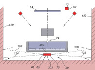
When reproducing a single violin sound source through a pair of loudspeakers, there are four arrivals (see Figure 1): two from the left speaker (one to the left ear and one to the right ear) and two from the right speaker (one to the right ear and one to the left ear). This reception of two additional acoustical crosstalk signals restricts the width the sound field to a span between the two loudspeaker (assuming no additional reflection or phase enhancements) and also causes artificial amplitude anomalies for monophonic signals due to the interference effects of the additional pair of crosstalk signals.
In 1962, two Bell Laboratories researchers, Bishnu Atal and Manfred Schroeder, began to address this two-loudspeaker acoustic-crosstalk issue. They filed a patent on their research into spatialized two-channel systems and were granted US Patent 3,236,949, “Apparent Sound Source Translator.” The researchers were among the earliest to lay the groundwork for the concept of employing crosstalk cancellation processing.
In the late 1960s, Volker Mellert and Peter Damaske extended and refined the initial work of Atal and Schroeder and were able to optimize a binaural processing system for loudspeakers that was quite effective at 360° image placement, including front to back discrimination. They even addressed reproduction in the median plane, a precursor to the current work of Dolby’s ATMOS system. Much of the improvement was due to refinement in the dummy head construction details and crosstalk cancellation processing (See: Peter Damaske & Volker Mellert [1969] “Ein Verfahren zur richtungstreuen Schallabbildung des oberen Halbraumes über zwei Lautsprecher,” published in Acustica 22: 153-162, and Peter Damaske [1971] “Head-Related Two-Channel Stereophony with Loudspeaker Reproduction” published in The Journal of the Acoustical Society of America 50 [4]: 1109-1115)
As more research was published on this topic, various companies started to look into how to commercialize this concept. One of the first of these commercial products was JVC’s BN-5 “Bi-phonic Processor” (1978-1982), developed primarily for reproducing binaural recordings through loudspeakers by way of crosstalk cancellation, but also having adaptive settings for use with conventional stereo program material. The system was based on numerous JVC patents, including US Patent 4,118,599, “Stereophonic Sound Reproduction System,” by inventors Makoto Iwahara and Toshinori Mori.
The simplified expression of the process JVC applied is that of adding two additional signals to the left and right channel outputs. The left channel input signal was inverted in phase, reduced in level, delayed by an amount corresponding to slightly less than an ear spacing width, and then mixed into the right channel output. The same process was performed on the right channel input and mixed into the left channel output. The idea was to substantially eliminate any crosstalk from the left loudspeaker to the right ear, and vice versa for a listener seated equidistant from the two loudspeakers.
But, as one can see, each crosstalk cancellation signal for one ear also has a portion that crosstalks back to the other ear, theoretically requiring an infinite sequence of amplitude reduced, recursive crosstalk cancellations to achieve equivalence with isolated binaural headphones when using loudspeakers. Fortunately, as with many corrective systems, improvements diminish significantly after just a few recursions. On all these systems, additional frequency shaping and level shifting is required to optimize performance.
Even in these early efforts, the spatial impressions were quite dramatic, and for program material carefully recorded on a well-designed dummy head, the image recreations were relatively faithful to the original source placements. But, on much of the program material, tonal coloration was easily detected. Popularizing a version of the JVC-type acoustic crosstalk processor with additional capability, Robert W. Carver developed the Carver Sonic Hologram Generator, which instead of being primarily optimized for the reproduction of idealized binaural recordings, was repurposed to playback conventional stereo recordings.
Carver’s initial patent on Sonic Holography was US Patent 4,218,585, “Dimensional sound producing apparatus and method.” Much of the novelty in the Carver signal processor was focused on multiple-delayed and amplitude-shaped versions of the out-of-phase crosstalk cancellation signal being summed into the primary channel signals to create a greater tolerance of head position and angle of the loudspeaker to the listener. Additional refinements were implemented in an attempt to minimize tonal colorations in these devices.
However, before the electronic processor versions of these systems were introduced in the US, Makoto Iwahara of JVC was already developing a passive acoustic crosstalk cancellation capability into the driver configuration of the loudspeaker itself. As disclosed in US Patent 4,199,658, “Binaural Sound Reproduction System,” wherein a second set of drivers spaced horizontally to the outside of the primary drivers, with a center-to-center spacing corresponding to the left-to-right ear spacing distance of a listener seated on a centerline position in front of the left and right loudspeakers. In the JVC implementation, the outer crosstalk correction driver of the right channel loudspeaker was connected to the left channel amplifier output in reverse phase, with a low-pass shaping filter in the crossover. As compared to the electronic processor approach, there is no delay required due to the inherent delay due to the horizontal driver spacing of a head width. Unfortunately, there doesn’t appear to be any products developed by JVC with this loudspeaker-based crosstalk cancellation configuration.
A few years after the Carver Sonic Hologram Generator popularized the concept using active processing, Matthew Polk at Polk Audio filed for its version of a passive, loudspeaker-based acoustic crosstalk cancellation system, and was granted a patent — US Patent 4,489,432, “Method and apparatus for reproducing sound having a realistic ambient field and acoustic image.”
One of the primary differences between the Polk Audio crosstalk cancelling loudspeaker and the original JVC version is that instead of merely reversing the phase and reducing the level of the additional crosstalk drivers, the Polk system connects the left and right (L-R) crosstalk drivers in series with each other and between the positive terminals of the left and right amplifier channels. This method derives an L-R signal to the left speaker crosstalk driver and R-L signal to the right speaker crosstalk driver, which inherently provides the phase reversed cancellation signal and appropriate level shifting needed for effective acoustic crosstalk cancellation and image expansion while maintaining a substantially timbre neutral and spatially central anchored mono signal.
While all of these crosstalk systems, going back to the original work of Schroeder and Damaske in the early 1970s, tend to operate on the same organizing principles, they also tend to succeed or fail based on how well they are implemented in terms of the fine details. As with the early binaural recording work, it was found that the dummy heads with artificial pinna had to be carefully matched to the real elements of a human listener, even including a correct torso formation. In the same vein, the later systems, when attempting to correct for head-related crosstalk, must have the cancellation correction signal coming directly from the left loudspeaker, perfectly match the level and frequency response shape with ideally matching opposing phase to that of the crosstalk signal coming around the face of the listener. In many of the systems, a simple low-pass filter was used, and others deployed shaping networks to better match the real-world crosstalk response.
Nearly 40 years after Polk Audio’s first patent filing on its Stereo Dimensional Array (SDA) loudspeaker, in the patent herein under review, it is now providing a new improved version addressing the “Head Related Transfer Function” issue, not by just implementing additional filtering, but primarily by reforming the front of the loudspeaker enclosure shape to more closely mimic the impact of acoustic waves “cross-talking” around a human face.
As can be seen in the original Polk SDA loudspeaker, as shown in Figure 2, the frontal baffle surface is substantially flat. The “outer” crosstalk cancellation driver had a direct, un-diffracted pathway to the ear of the listener, whereas the unwanted crosstalk signal that it was attempting to inversely emulate from the opposing loudspeaker must traverse around the face to the opposite ear, changing frequency response. With this format, the correction signal will only be able to partially cancel the crosstalk signal, since they are not effectively matched.
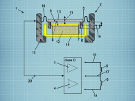
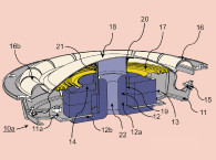
In the new system, as can be seen in Figure 3 and Figure 4, the primary and the crosstalk correction drivers are angled back such that a virtual “nose” is formed on the front of the enclosure, causing a diffracted amplitude response that more effectively mimics that of the crosstalk waveform moving across the listener’s face.
The effect is further refined by the angled drivers being designed such that the crosstalk driver’s off-axis response forms an additional factor toward the optimal response. Last, a final amplitude trimming network is placed in the crosstalk arm of the crossover network to complete the task of maximizing the match to the ideal head-related transfer function, allowing the system to have a much more complete and precise crosstalk cancellation outcome (see Figure 5).
By having the acoustical crosstalk cancellation being realized in the formation of the loudspeaker structure instead of with an active signal processor, there are a number of advantages. When the distance between the primary and the crosstalk drivers corresponds to an actual left to right ear spacing, the delays are inherently adapted as the listener sits closer or further from the loudspeakers or if the distance between the left and right loudspeakers is changed. Also, with these same-use model variations, with the new Polk baffle formation, the amplitude changes in the head-related transfer function are also tracked more accurately without adjustment of the signal. In the active processor approach, any of these changes in listener-loudspeaker relationship ideally requires calibrated, adaptive changes in phase and amplitude to maintain effective cancellation and minimize tonal coloration.
Based on the limitations of the prior art and gauging the parameters that have the greatest effect on crosstalk system performance, the refinements disclosed in the new Polk Audio patent, properly implemented, will most likely provide useful improvements in the application of crosstalk cancellation systems to loudspeakers. VC
This article was originally published in Voice Coil, February 2019