Double Coil Speaker
Patent Number: US9838794B2
Inventors: Friedrich Reining (Vienna, Austria)
Assignee: Sound Solutions International Co., Ltd. (Beijing, China)
Filed: April 26, 2013
Current CPC Class: H04R 1/347 20130101
Granted: December 5, 2017
Number of Claims: 11
Number of Drawings: 8
Abstract from Patent
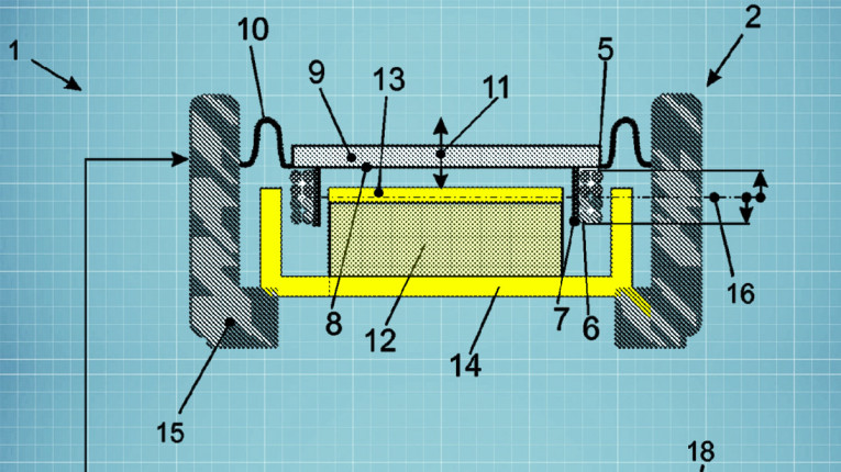
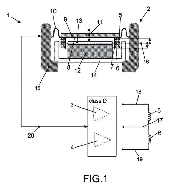
An audio system comprising an electro-acoustic transducer having two stacked voice coils mechanically linked to a membrane. The voice coils are oscillatingly suspended in the magnetic field of a permanent magnet focused by a pole plate and are mechanically arranged symmetrical to the pole plate while in a rest position. The audio system further comprises two driver circuits connected to the electro-acoustic transducer.
Independent Claims
1. An audio system comprising: an electro-acoustic transducer comprising: a membrane; a permanent magnet; a pole plate configured to focus the magnetic field of the permanent magnet; a first coil mechanically linked to the membrane; a second coil mechanically linked to the first coil, the first coil and second coil being oscillatingly suspended in the magnetic field of the permanent magnet; wherein the first coil is stacked on top of the second coil in the direction of movement of the membrane, the first coil and the second coil further being mechanically arranged symmetrically about a midline of the pole plate in a rest position, the midline being substantially perpendicular to the direction of movement of the membrane; and a first driver circuit and a second driver circuit, the first and second driver circuits being connected to the electro-acoustic transducer.
Reviewer Comments
Producing low-frequency woofer transducers with significant excursion capability while attempting to utilize practical, cost-effective magnetic assemblies of a reasonable size can frequently result in conflicting requirements. With conventional loudspeaker motor architectures, a large mechanical excursion, while maintaining substantially constant electromagnetic motor strength (BL), requires motor structure with a long voice coil with large overhand beyond the length of the magnetic pole piece magnetic gap (or a long pole piece with an under-hung voice coil). Ignoring the variations in fringe flux that exists in differing amounts beyond the length the magnetic gap, the amount of overhung voice coil turns for a given set of parameters will result in greater linear excursion in exchange for lower BL and efficiency. If the voice coil is the same length as the magnetic gap then the efficiency will be maximized, but linearity with excursion will be compromised. It would be great if one could have the entire voice coil turns immersed in the majority of the length of the magnetic gap throughout the full mechanical excursion limit.
Several solutions to this problem have been attempted over the years with many that were more theoretically impressive than practical. One example of a hopeful solution was a clever one by Tom Danley and Charles Rey, shown in US 4,531,025, “Loudspeaker with Commutated Coil Drive,” created when they were at Intersonics, Inc. in the 1980s. Their idea was to have the surface of the linear coil operate as a commutator and instead of the electrical connections being at each end of the voice coil wire, the electrical connection to the voice coil was through a set of conductive brushes at each end of the magnetic gap, such that as the voice coil/diaphragm was displaced, any amount of voice coil hanging over the end of the magnetic gap was “bypassed” and the connection to the voice coil always activated just the amount of turns that were actually within the gap length at any given moment. As much as this looked great on paper, the electro-mechanical problems to realize a practical device were unfortunately insurmountable and inspired the move to solve the problem with the innovative rotary driven woofer systems later produced by Intersonics.
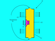
The disclosed invention in the patent under review is a split-coil architecture, wherein two coils are placed end on end such that their total summed length is the same length as the magnetic gap. The outer ends of the each coil is driven by a separate amplifier output stage, with, in one embodiment, the center ends of the coils joined together and connected to ground. The coils can be driven by a number of amplifier configurations, such as a positive half of the power stage driving one coil and the negative half of the power stage driving the second coil, with the two coils tied to a common ground, or each coil driven by a complete output stage and floating independently of each other. With this configuration, even during significant excursions, the total turns of the active coil is always totally immersed in the magnetic gap, proving about 50% greater linear excursion for a given motor scale/cost, as compared to an under-hung coil.
The patent text teaches the application of the dual voice coil system to achieve a number of additional potentially useful attributes. One of which is to use controlled, bidirectional DC offsets to overcome the air-spring stiffness of an enclosure volume. In this approach, a constant DC applied to each coil to simulate an active “negative spring” as the coil moves the diaphragm in to compress or expand the enclosure air spring, lowering the effective fundamental resonant frequency of the loudspeaker system. This approach was attempted by others in England in the 1980s, and while the technique was effective in significantly reducing the resonant frequency of a system, the energy requirements and thermal increase in the voice coil(s) was substantial, and ultimately the equivalent end result was much better achieved by way of simple equalization to accomplish the same low frequency bandwidth extension. Applying DC to a voice coil independent of program crest factor is very inefficient.
Very little is disclosed in the patent relative to compatible amplifier design and the effects on the amplifier. The drawings show a Class-D amplifier being used in the illustrated examples, but there is no mention of amplifier type in the patent disclosure.
As is often the case, this type of system was developed previously by Martin Nagel in 1976, as disclosed in his patent, US 4,130,725, “Split-Coil Speaker with Direct Coupling,” which was developed at Tenna Corp. in Warrensville Heights, OH. It is not known to have resulted in a commercial product. Part of the reason may have been the use of standard linear amplifiers at the time.
In the late 1980s, Robert Williamson thoroughly explored this configuration, and while the approach was found to be potentially advantageous, it was difficult to get it to work reliably with linear power amplifiers due to the transformer effect of the active coil inducing a reverse voltage to the undriven coil causing damage to the power amp’s opposite polarity output stage
During Williamson’s research he found that when using signal tracking, rail-to-rail adaptive power supply amplifiers, or Class-D amplifiers, the reverse currents of the dual-coil transformer effects could be absorbed back into power supply through the anti-parallel diodes of the switch-mode based power amps, providing a solution to the reliability concerns with the linear, Class-B amplifiers.
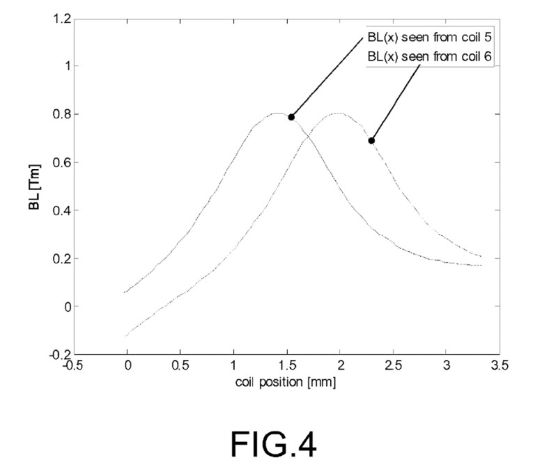
With fully active systems, Williamson also found that by physically separating the voice coils by at least half the length of the voice coil gap, when using motional feedback or predictive processing, one could correct for the non-linearities of the non-constant BL at zero crossing between the separated voice coils and achieve greater excursion capability with maximum efficiency and linearity at the excursion limits.
Ultimately, this approach has been tried a few times over the years but without any significant practical commercial application. While the basic approach disclosed in the current patent appears to generally duplicate the efforts of the prior art and the inventors may have utilized Class-D amplification to provide a more reliable solution, it remains to be seen if the advantages realized with the greater complexity pass a cost/benefit comparison to other approaches providing equal or greater performance.
That said, in reviewing the Williamson research into this topology, it was found that there were certain variables that could be coordinated to achieve some significant performance gains and it would appear to be a system that has not yet been utilized at its full potential and awaits an even more effective execution of the idea. VC
This article was originally published in Voice Coil, March 2018.