 Knurled Speaker Diaphragm
Patent Number: US20160142824A1
Patent Application Number: 2016/0142824
Inventor: Daniel W. Clark (San Diego, CA); Frederick Bruce Thigpen (Tallahassee, FL)
Assignee: MrSpeakers, LLC (San Diego, CA)
Filed: November 19, 2015
Current US Class: 381/423
Current CPC Class: H04R 2207/021 20130101
Published: May 19, 2016
Granted: December 26, 2017
Number of Claims: 20
Number of Drawings: 17
Abstact from Patent
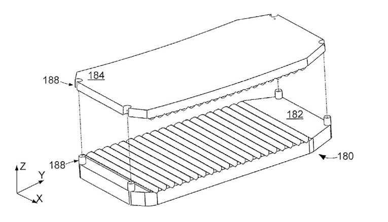
A speaker may be configured with at least one diaphragm positioned proximal to and separated from an array of magnets. The diaphragm may consist of a substrate and at least one patterned electrically conductive trace with a portion of the diaphragm knurled to provide a ridge extending a height above the diaphragm that is at least twice a thickness of the diaphragm.
Independent Claims
1. An apparatus comprising a diaphragm positioned proximal to and separated from a first array of magnets, the diaphragm comprising a substrate attached to at least one patterned electrically conductive trace, a portion of the diaphragm knurled to provide a ridge extending a height above the diaphragm that is at least twice a thickness of the diaphragm.
10. An apparatus comprising a diaphragm positioned proximal to and separated from a first array of magnets, the diaphragm comprising a substrate attached to at least one patterned electrically conductive trace, a portion of the diaphragm knurled with a plurality of ridges each extending a height above the diaphragm that is at least twice a thickness of the diaphragm.
18. A method comprising: positioning a diaphragm proximal to and separated from a first array of magnets, the diaphragm comprising a substrate attached to at least one patterned electrically conductive trace; and knurling a portion of the diaphragm to provide a ridge extending a height above the diaphragm that is at least twice a thickness of the diaphragm.
Reviewer Comments
Planar magnetic transducers are generally divided into two categories:
- Free floating, “‘pure ribbons,” which are usually solid aluminum foil rectangular diaphragms that are only attached to the transducer frame at each end of the rectangle and are, for the most part, unattached on the sides along the length of the rectangle, on the order of 0.25” to 1.5” wide by anywhere from 2” to 6’ tall
- Ortho-dynamic, or clamped diaphragm, “quasi-ribbons,” with a conductive pattern attached to a thin film, non-conductive substrate
All of these original, pure-foil ribbon diaphragms were pleated or corrugated across the short dimension to reduce resonant modes and distortion, while providing a low fundamental resonant frequency considering the very low mass. These ribbons were considered an electro-magnetic acousti-mechanical equivalent of an electrostatic transducer, due to the equal force over area drive and low moving mass.
The second type of planar magnetic transducer was originally patented in 1923 in Germany by Dr. Hans Riegger, of Siemans, as the “Electro-dynamic Telephone” (DRP 410,114) and later commercialized in by Siemens in the 1930s, as the Blatthaller. The Blatthaller diaphragm was corrugated but due to the rather massive and rigid (by modern standards) layered moving structure, the corrugation did not provide the benefits of current devices. The sandwich-style diaphragm was said to use a copper or type of aluminum conductor over an insulated substrate that has been said to consist of everything from insulted metals to stretched sheets of various animal parts. This second type of planar magnetic (sans the catgut substrate) is the subject of this patent review.
Most planar magnetic conductor over insulated substrate loudspeakers, produced after the Blatthaller (e.g., the first commercially successful modern systems), developed and commercialized in 1972 by James Winey of Magnepan (US 3,674,946) used flat, stretched diaphragms, without any pleats or corrugations. The planar magnetic transducer, used in the Carver Amazing Loudspeaker, developed by the late David Graebener, Jeff Hammerstram, and myself, (circa ~1986) was the first large area planar magnetic device, with complete circumferal attachment, to utilize corrugated diaphragms to minimize spurious resonance and distortion. Since corrugations had been used in pure ribbon microphones and tweeters, at the time, it wasn’t considered to have adequate novelty to be patented.
In 1997, talented audio system developer Bruce Thigpen filed a patent, “Planar magnetic transducer with distortion compensating diaphragm,” (US 6,104,825), which patented the concept of knurling the diaphragm to form corrugations across the short dimension of the moving film structure. As is often the case, the patent office only searches prior art patents, and ignores technical papers or commercial products, unless that information is provided by the inventor. The same Bruce Thigpen is the co-inventor of the current patent under review, along with the founder of MrSpeakers headphone company, Daniel Clarke.
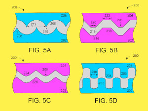
In the patent the claim is made that the diaphragms are corrugated, not for the purpose of distortion and resonance reduction, but instead, to lower the fundamental resonant frequency and, therefore, increasing low-frequency bandwidth.
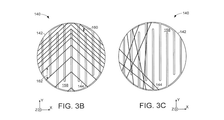
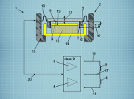
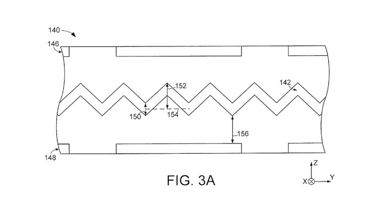
The novelty is that the corrugation depth is to the degree that the “height” of each “ridge” extends above the diaphragm by a distance greater than twice the thickness of the diaphragm (see Patent Diagrams 1 and 2). This dimensional definition of the corrugations were used in the Carver Amazing Loudspeakers in the 1980s and also later in many of the planar magnetic transducers developed by Graebener in his work for Wisdom Audio.

The patent office had originally rejected all the claims of the patent, due to the Thigpen’s previous US 6,104,825 patent, but eventually succumbed to the arguments of the inventors — that the taller corrugations were fundamentally different and serving a different purpose (resonant frequency reduction) than the shallower corrugations of the 6,104,825 patent, which were merely intended for distortion reduction, even though the original patent didn’t define or limit the corrugation to a shallower height dimension. (It is actually difficult to corrugate a planar magnetic diaphragm and end up with the corrugation height less than twice the film thickness.)
However, the patent has received a notice of allowance. Regardless of the level of novelty, the corrugated structure, with the corrugation height as defined, can provide a significant improvement by reducing spurious resonance and distortion and also lowering the fundamental resonant frequency and bass extension as compared to a standard, tensioned, non-corrugated, thin-film diaphragm. The assignee, MrSpeakers, is currently in the headphone business, and that appears to be the intended application for the technology, which should provide a useful basis to develop high-performance headphones. VC
This article was originally published in Voice Coil, December 2017.
Article update with information from the patent grant.