The following loudspeaker-related patents were filed primarily under the Office of Patent and Trademarks classification 181 for acoustical devices and 381 for electrical-signal processing systems and HO4R for international patents. This also includes new patent applications that are published in the Patent Application Journal.
Structure of Speaker
Application Publication Number: 20100183171
Inventors: Yueh-Hua Hsu Huang (Taipei Hsien, Taiwan); Ching-Hui Huang (Taipei Hsien, Taiwan)
Assignee: Jazz Hipster Corp. (Taipei Hsien, Taiwan)
Filed: January 21, 2009
Class: H04R 1/02
Published: July 22, 2010
Number of Claims: 4
Number of Drawings: 7
Abstract from Patent
An improved structure of a speaker comprises a cone frame, a surround, and a diaphragm, wherein a circumference of the diaphragm is sealed to an edge of an opening of the cone frame. A container portion is disposed on an inner side of the opening of the cone frame. The surround is disposed between the diaphragm and the container portion of the cone frame. Therefore, when an audio-frequency electrical signal is coupled with a voice coil inside the cone frame, the voice coil outputs an audio signal to drive the diaphragm to move and generate a sound. The present invention uses the surround to let the diaphragm move up and down with less resistance, which helps the diaphragm move more smoothly and reduces a distortion of sounds and increases the sensitivity of sound pressure level by enlarging the diaphragm moving area.
Independent Claims
1. An improved structure of a speaker, comprising: a speaker unit at least comprising a diaphragm, a cone frame, and a surround; wherein the speaker unit is characterized in that the surround is disposed between the diaphragm and the cone frame, a circumference of the diaphragm is sealed to an edge of an opening of the cone frame, a container portion is disposed on an inner side of the edge of the opening of the cone frame, and the surround is disposed in the container portion.
Reviewer Comments
When a low-frequency transducer is developed, whether for use in a large-scale or miniature loudspeaker device, often the situation calls for maximizing transducer diaphragm surface area (Sd) for a given total frontal dimension of the transducer and the mounting surface. There have been many transducer architectures developed in an attempt to achieve this desired increase in Sd for a given mounting frame, with two of the most recent being those developed by Enrique Stiles in US Patent 7,031,487, assigned to Step Technologies, and by Ronnie Espiritu in US Patent 7,548,631, assigned to Harman International.
The current patent application under review discloses a different format with the goal of both expanding the effective diaphragm surface area, for a given loudspeaker chassis diameter, and to provide a suspension that is more linear and arranged for reduced audibility of any nonlinearities that are generated during large diaphragm/suspension excursions.
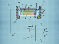
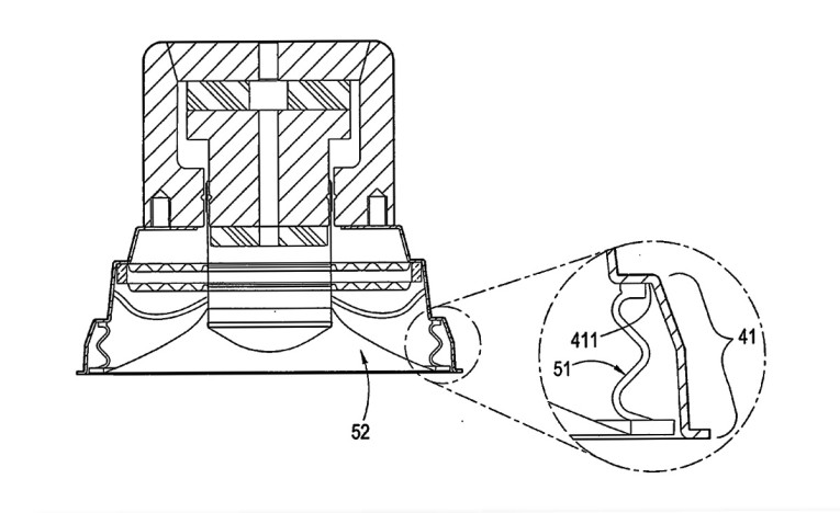
As can be seen in Figure 2C of the patent drawings, there is no suspension around the periphery of the diaphragm as exists in conventional low-frequency transducers. Instead, the diaphragm diameter is extended all the way to the inner edge of the speaker frame, and a bellows-type suspension is connected to, and located under, the outer edge of the diaphragm. This provides an approach that does maximize the actual physical surface of the diaphragm for a given frame size.
The inventor’s diaphragm/suspension configuration is substantially identical that of the Joris A. M. Nieuwendijk, et. al. as shown in US Patent 4,547,631, “Large Excursion Electroacoustic Transducer,” assigned to Philips in the mid 1980s.
Both of these devices have a large physical Sd (for the given frame size) and are capable of large excursions, but have some of the same (apparently) unforeseen drawbacks (similar to the patent reviewed in the June 2016 issue of Voice Coil, US Patent 9,288,561) wherein the bellows-type surround itself operates as a type of Heil Air Motion transformer, and as the diaphragm traverses a positive excursion to provide a compression wave of a given cubic displacement, the bellows can provide somewhat of a negative excursion and provide a rarefaction wave out-of-phase and cancelling a portion of the positive polarity compression. Since the surface area of a practical bellows is much less than that of the diaphragm surface itself, the effect may be small. But, it may represent a cancellation of about the same amount of diaphragm area increase that was allowed by use of the bellows suspension. (One can easily test this from a DC standpoint by squeezing any bellows-type device and feel a positive airflow from the sides of the bellows when compressing suspension.)
This can also cause a “whistling” effect as the air moves in and out of the small opening between the frame and the diaphragm. Depending on the bellows design, these effects can be minimized to a substantial degree but are difficult to eliminate. Other issues arise with these types of systems, one of which is that the bellows can be unstable and cause the diaphragm to “rock” during excursion. This can be substantially mitigated by the use of dual spiders, spaced apart to provide stability to the moving system. As can be seen in Figure 2C, this approach has been incorporated into the invention of this review.
Another issue is that of nonlinear compliance as one moves from a compression of the bellows structure to an expansion during positive and negative excursions. The bellows configuration tends to have a different effective compliance when stretching vs. compressing. Some conventional surround suspensions can also suffer from this effect, particularly near their elastic limits.
A good solution to this issue, relative to bellows-type suspensions, was developed in the late 1950s by J. A. King, as illustrated in his patent US 3,019,849, “Loudspeaker Diaphragm Suspension.” He attached the diaphragm half way along the bellows, so that the same number of suspension “pleats” were above and below the diaphragm. In this configuration, half of the bellows is expanding while the other half is contracting. The differential compliance is balanced, or cancelled out, such that the stiffness of the suspension is substantially constant throughout both positive and negative diaphragm excursions. In the early 1980s, Pioneer of Japan applied this technique to a semi-bellows form of dual spiders to maintain constant compliance over a wide range of diaphragm displacement. In an Audio Engineering Society (AES) paper, Pioneer illustrated a substantial reduction in measured distortion.
While these types of suspensions are not novel, and have been used effectively in the past, they tend to be applied less often these days, partly due to the high performance that has been realized from standard, well-designed roll-surrounds, and also because conventional surround suspension systems lend themselves more effectively to low-cost assembly techniques. VC
This article was originally published in Voice Coil, July 2016.