Dual Coil Electrodynamic Transducer with Channels for Voice Coil Cooling
Patent Publication Number: US 2018/0206040
Inventor(s): Ralph E. Hyde (Santa Clara, CA)
Assignee: Harman International Industries, Inc., Stamford, CT
Filed: January 13, 2017
Current CPC Class: H04R 9/063 20130101
Published: July 19, 2018
Number of Claims: 20
Number of Drawings: 6
Abstract from Patent
An electromagnetic transducer includes a diaphragm movable relative to a central axis, a magnetic assembly axially spaced from the diaphragm, and a magnetic gap annularly disposed about the central axis. A voice coil is coupled to the diaphragm and includes spaced first and second coil portions which are at least partially disposed in the magnetic gap. A housing includes a rear frame surrounding and supporting the magnetic assembly, the rear frame having an annular well portion in fluid communication with the magnetic gap. At least one channel is formed in the rear frame in fluid communication with the well portion and extends outwardly beyond the well portion in a radial direction. A vent is provided on an outer surface of the rear frame in fluid communication with the at least one channel, wherein air exits the transducer via the vent to transfer heat from the transducer to the ambient environment.
Independent Claims
1. An electromagnetic transducer, comprising: a diaphragm movable relative to a central axis; a magnetic assembly axially spaced from the diaphragm, the magnetic assembly having a magnetic gap annularly disposed about the central axis; a voice coil coupled to the diaphragm, the voice coil including at least a first coil portion and a second coil portion axially spaced from each other and at least partially disposed in the magnetic gap, wherein passing an electrical signal through the voice coil causes the voice coil and diaphragm to oscillate; a housing having a front frame surrounding the diaphragm and a rear frame surrounding and supporting the magnetic assembly, the rear frame having an annular well portion in fluid communication with the magnetic gap, wherein a cross-sectional area of the well portion is greater than a cross-sectional area of the magnetic gap; at least one channel formed in the rear frame in fluid communication with the well portion, the at least one channel extending outwardly beyond the well portion in a radial direction; and a vent provided on an outer surface of the rear frame in fluid communication and aligned with the at least one channel, wherein air flow through the magnetic gap, the well portion and the at least one channel is generated by movement of the diaphragm, and air exits the transducer via the vent to transfer heat from the transducer to the ambient environment.
10. An electromagnetic transducer, comprising: a diaphragm movable relative to a central axis; a magnetic assembly axially spaced from the diaphragm along the central axis and including an inner magnetic portion and an outer magnetic portion, wherein the outer magnetic portion is coaxially disposed about the central axis and radially spaced from the inner magnetic portion, and wherein an annular magnetic gap is defined between the inner and outer magnetic portions; a voice coil coupled to the diaphragm, the voice coil including at least a first coil portion and a second coil portion axially spaced from each other and at least partially disposed in the magnetic gap, wherein passing an electrical signal through the voice coil causes the voice coil and diaphragm to oscillate; a housing having a front frame surrounding the diaphragm and a rear frame surrounding and supporting the magnetic assembly, the rear frame having an annular well portion in fluid communication with the magnetic gap, wherein a cross-sectional area of the well portion is greater than a cross-sectional area of the magnetic gap; at least two channels formed in the rear frame in fluid communication with the well portion, the at least two channels each extending outwardly beyond the well portion in a radial direction; and a vent provided on an outer surface of the rear frame in fluid communication and aligned with each of the at least two channels, wherein air flow through the magnetic gap, the well portion and the at least two channels is generated by movement of the diaphragm, and air exits the transducer via the vents to transfer heat from the transducer to the ambient environment.
11. An electromagnetic transducer, comprising: a diaphragm movable relative to a central axis; a magnetic assembly positioned forward of the diaphragm, the magnetic assembly having a magnetic gap annularly disposed about the central axis; a voice coil coupled to the diaphragm, the voice coil including at least a first coil portion and a second coil portion axially spaced from each other and at least partially disposed in the magnetic gap, wherein passing an electrical signal through the voice coil causes the voice coil and diaphragm to oscillate; a housing having a rear frame surrounding the diaphragm and a front frame surrounding and supporting the magnetic assembly, the front frame having an annular well portion in fluid communication with the magnetic gap, wherein a cross-sectional area of the well portion is greater than a cross-sectional area of the magnetic gap; at least one channel formed in the front frame in fluid communication with the well portion, the at least one channel extending outwardly beyond the well portion in a radial direction; and a vent provided on an outer surface of the front frame in fluid communication and aligned with the at least one channel, wherein air flow through the magnetic gap, the well portion and the at least one channel is generated by movement of the diaphragm, and air exits the transducer via the vent to transfer heat from the transducer to the ambient environment.
Reviewer Comments
Because of the fact that in the majority of dynamic driver-based loudspeakers the voice coil’s DC resistance component is significantly greater than the transducer’s motional impedance, much of the program signal current flowing through the voice coil is converted into heat instead of acoustic output. (For example: A particular 7.8 Ω driver has a DC-Re of 6.6 Ω, and therefore, a motional impedance of approximately 1.2 Ω.) Having thermal limits exceeded in the voice coil of a loudspeaker transducer can cause a variety of problems — from an increase in voice coil resistance, causing loss of efficiency, crossover frequency shifting, driver level shifting, and compression of the audio signal to voice coil failure, in more extreme cases.
Since the heat being emitted from the voice coil may be transferred to other operative components of the loudspeaker (e.g., the magnetic assembly and the coil former and its attachment to the diaphragm and spider secondary suspension), the excessive heat may damage the components of the loudspeaker and/or degrade the adhesives employed to attach various components together, and may ultimately cause the loudspeaker to cease functioning.
Thus, the generation of heat limits the power handling capacity and the distortion-free acoustic output capability of loudspeakers as well as their efficiency as electro-acoustical transducers. Such problems are exacerbated when one considers that electrical resistance through a voice coil increases with increasing temperature, such that, as the hotter the wire of the voice coil becomes, the higher its electrical resistance becomes and, therefore, the more heat it generates — a vicious circle that can cause thermal runaway, particularly in a system with motional feedback or current drive amplifier output stages that apply more power to compensate for thermal-resistive losses.
The most common form of a loudspeaker uses a single voice coil winding in a single magnetic gap, but Harman/JBL has adopted dual voice coil structures in their high output woofer devices. Therefore, the patent also explores the notion that loudspeaker performance may be enhanced by using a multiple coil/multiple gap design.
In this case, a multi-coil transducer may include two or more separate windings axially spaced apart from each other to form two or more coils, and the same wire may be employed to form the coils. The multiple voice coils are usually electrically connected together either on the coil itself or on the outside of the loudspeaker so that the coils work together to move the diaphragm. As both coils provide forces for driving the diaphragm, it is stated that the power output of the loudspeaker may be increased without significantly increasing size and mass with the most common implementation of the multiple coil loudspeaker using two voice coils and two magnetic gaps.
Many multi-coil/multi-gap designs are able to produce more power output for a given transducer motor mass and dissipate more heat than conventional single-coil designs. For example, a dual-coil design provides more coil surface area compared with many single-coil configurations, and is capable of dissipating a greater amount of heat at a greater rate of heat transfer.
The patent states that while the multiple coil/multiple gap construction has several advantages over single gap designs including higher power handling, reduced distortion, reduced inductance, and extended frequency response, there are at least three particular disadvantages with dual coil/dual gap speakers.
First, insofar as a desired advantage of the dual-coil driver being its ability to operate at a greater power output, by operating the dual-coil transducer at the higher power output also causes the dual-coil transducer to generate more heat. Hence, the improved thermal capability inherent in the dual-coil design may be offset by the greater generation of heat. There can be problems with overheated magnets due to the compact motor with smaller thermal mass and the proximity of the magnets to the heat-generating voice coils. For example, as compared to single-coil transducers, adequate heat dissipation in many dual-coil transducers, and more generally multiple-coil transducers, continues to be a problem due to the longer thermal paths that must be traversed between the heat source (primarily the voice coil) and the ambient environment.
In attempt to provide transducer cooling, the pole piece may be formed with a center vent, which provides a flow path for the transfer of cooling air from outside of the transducer. Airflow through this vent is created in response to movement of the diaphragm with the excursion of the voice coil. However, such designs do little to directly cool the transducer voice coil, since in many cases hot air is simply pumped back and forth in the pole piece. In fact, in some cases, a very large center vent reduces convective cooling in proximity of the voice coil, actually reducing power handling of the transducer.
In some instances, holes or slots may be formed radially within the pole piece and extend outward from the center vent toward the voice coil in an attempt to provide convective cooling to the voice coil. Such radial holes may be effective to cause cooling air from the center vent to flow directly against at least a portion of the voice coil, but the position and the shape of these holes (or slots) does not efficiently pull air toward the voice coil and disturbs the laminar air flow within the center vent, creating turbulence and drag. Furthermore, spurious acoustic problems can be created with such radial slots, as a large amount of air is forced through a small passage.
One method to attempt to more directly cool the voice coil is by forcing air through the narrow magnetic gap between the voice coil and motor at high velocity. This results in an air-cooling of the voice coil, but also causes a forced air transfer of heat to the magnet parts. Another method to cool the voice coil directly, as well as the overall transducer, is to transfer heat directly from the voice coil to the ambient air, bypassing the magnet subassembly entirely. This can be accomplished by forcing air past the hot voice coil through the magnetic gap and exhausting it through vents to the ambient. However, the high velocity of air that is desired in the gap through vents that connect directly to the magnetic gap can be a significant source of noise.
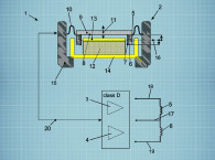
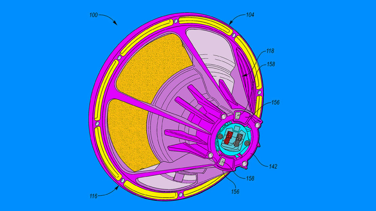
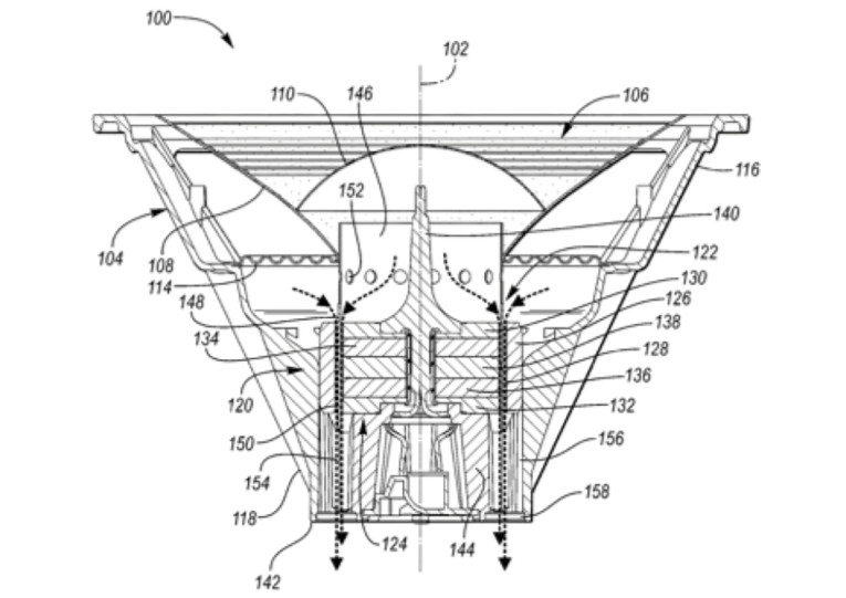
In the solution disclosed in the patent, a voice coil is coupled to the diaphragm, the voice coil including at least a first coil portion and a second coil portion axially spaced from each other and at least partially disposed within the magnetic gap (see Figure 1). The loudspeaker structure has a rear frame surrounding and supporting the magnetic assembly, the rear frame including an annular well portion in fluid communication with the magnetic gap, wherein a cross-sectional area of the well portion is greater than a cross-sectional area of the magnetic gap. At least one channel is formed in the rear frame in fluid communication with the well portion, with the channel extending outward beyond the well portion in a radial direction. A vent is provided on an outer surface of the rear frame in fluid communication, and aligned with at least one channel, wherein air flow through the magnetic gap, the well portion, and at least one channel, is generated by movement of the diaphragm, and air exits the transducer via the vent to transfer heat from the transducer to the ambient environment.
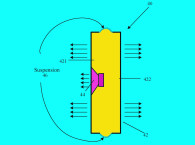
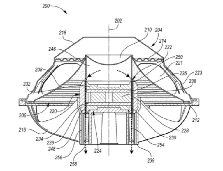
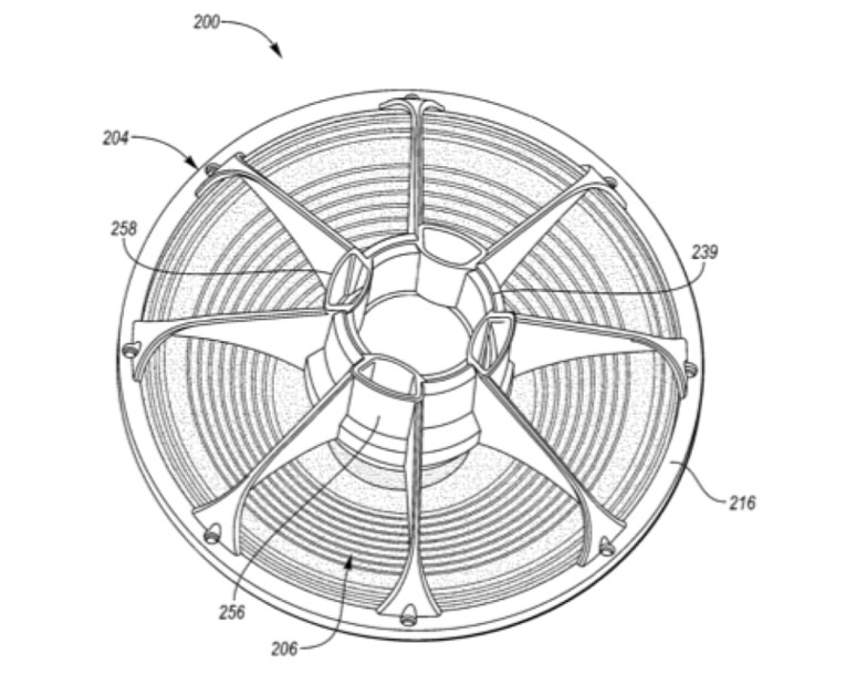
In another embodiment of the invention a similar structure is configured with the magnetic assembly positioned forward of the diaphragm, external to the loudspeaker enclosure, and air exits the transducer via the vent to transfer heat from the transducer to the external ambient environment. Various additional embodiments are disclosed with minor variations in pathways and openings, while still following the basic recipe (see Figure 2).
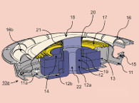
Although no specific limitations are placed on the dimensions of the channels 156 or vents 158 (as numbered in Figure 3), certain factors are generally considered in the sizing of the channels 156 and vents 158. For instance, channels 156 and vents 158 that are too small in cross-section may result in excessive air noise and if they are too large in cross-section or length, they may not adequately exchange heat with the ambient environment. In one example, the path length of each channel is approximately 5 cm but this is not stated as necessarily being an optimal length, which may be scaled depending on the overall size of the transducer and magnetic structure.
In another example, the channel 156 has a substantially similar cross-sectional area as the vent 158, and the cross-sectional area of the channel 156 may remain relatively constant along its length. As such, a path length between the magnetic gap 128 and the vent 158 may be provided where the cross-sectional area for airflow does not change radically. The constant cross-section and adequate size of the disclosed channel airflow path prevents turbulent and noisy airflow and results in very quiet venting of air. It is suggested that any noise generated internally by high air velocity in the magnetic gap 128 is sufficiently contained internally within the transducer 100 to prevent that noise from reaching the ambient. This may be more of a problem in the embodiments with the magnetic structure on the front side of the diaphragm, wherein the cooling system exits directly into the external environment.
There has been a lot of work in the category of voice coil cooling for woofer transducers that utilize diaphragm excursion to move air relative to the voice coil. While in some transducer architectures this can be effective at low frequencies for which high input power results in large voice coil/diaphragm excursions. But for the upper end of the passband for these large woofers, where the input power densities can be the greatest, there may not be significant diaphragm excursions and, therefore, very little cooling, even though the voice coil may be dissipating heat as much or more than at the lower, high excursion frequencies.
There have been dozens of patents on various forms of magnetic motor structures to enhance cooling. At the assignee of this patent, Harman International, there has been significant work in this regard, including the earlier work by Doug Button, as expressed in his 1989 patent, “Self-cooled loudspeaker,” US Patent 5,042,072, with the distinctive language in the independent claim of “the magnetic structure having a plurality of passages extending from the magnetic gap completely through to the other side of the magnetic structure and wherein each passage is continuous with a corresponding discrete enlargement in the cross-sectional area of the magnetic gap so as to allow air driven by the diaphragm to flow past the voice coil without an excessive pressure drop,” suggesting a design that doesn’t dramatically differ from how the current patent under review is claimed, except for the inclusion of the “discrete enlargement in cross-sectional area” language.
So far, the patent office has rejected the claims for the current patent application due to an earlier application filing, US Patent 2015/0271605, “Multi-Driver Transducer Having Symmetrical Magnetic Circuit and Symmetrical Coil Circuit,” by inventor Fan Zhang. That doesn’t mean this case won’t be granted since in many first office actions, patent examiners will reject all claims, wherein it is up to the inventor and his lawyers to argue away the objections.
As a last observation — something in common among many of these “cooling structure” patents is that while they provide a pathway for heated air to flow — the movement of the diaphragm is not the same as a fan. A fan causes DC airflow, whereas a loudspeaker diaphragm causes AC airflow, which in most cases just moves hot air back and forth across the voice coil and actually removes very little hot air out into the ambient environment.
One of the more interesting exceptions was the Nordschow-Wright loudspeaker motor, as disclosed in US Patent 5357586A, by David Nordschow, Terry Taylor, and Robert Wright, of The Nordschow-Wright Loudspeaker Co. The cooling structure built into the loudspeaker’s motor includes what is the equivalent of a thermal rectifier, such that upon the diaphragm and voice coil of the woofer moving forward and back, in response to an AC input single, the aerodynamic thermal waveguide induces more air movement out of the motor in one direction the other direction, causing a net heated air escape while drawing in cool air over the voice coil from a different entrance.
This reviewer had the pleasure of viewing a demonstration of the proof of the system’s net air movement by using the woofer as a means to fill up a large garbage bag, just like blowing up a balloon. It took less than a minute to completely fill the 20-gallon bag. The Nordshow/Wright system was very effective at actual, hot air removal by way of a very simple structure. And, as of 2011, that patent ran its course and it is in the public domain, available to anyone who wishes to use it. VC
This article was originally published in Voice Coil, September 2018.