New Planar-Pivot (Planot) Transducer
Invented by John J. Gaudreault and covered by a US Patent #7860265, the Planot transducer design yields a unique single full-range driver. The geometry, apparently never before used in a diaphragm, is three-dimensional triangle shape (3D-Diaphragm), as opposed to two-dimensional cone or ribbon diaphragms. The invention’s geometry allows for a pivoting motion, as opposed to the pistonic motion of two-dimensional diaphragms.
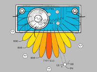
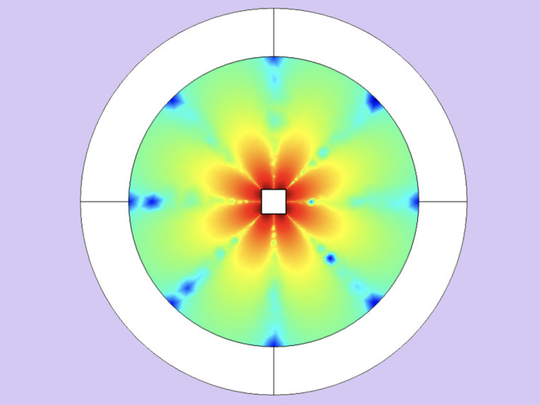
These two factors and others set the Planot apart from all other loudspeaker drivers. Figure 1 shows that the diaphragm has at least three equal sides. Other implementations may have larger even numbers of sides (4, 8, or 16, and so on). The edges of the functional sides are parallel to the pivotal axis. Each "side" of its “cross section” could be .75" to 1" long. The diaphragm length could be between 1 and 4′ long.
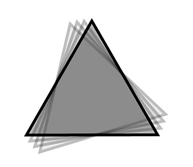
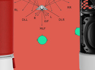
No enclosing structure such as a box, enclosure, or baffle is required. Eliminating the box eliminates all of the negative attributes of a box such as diffraction of sound off the outside of the box, internal reflection of sound inside the box, sound generated by box vibration, and the associated costs of building an enclosure (Fig. 2). The Planot’s diaphragm radiates 360° and thus requires no box.
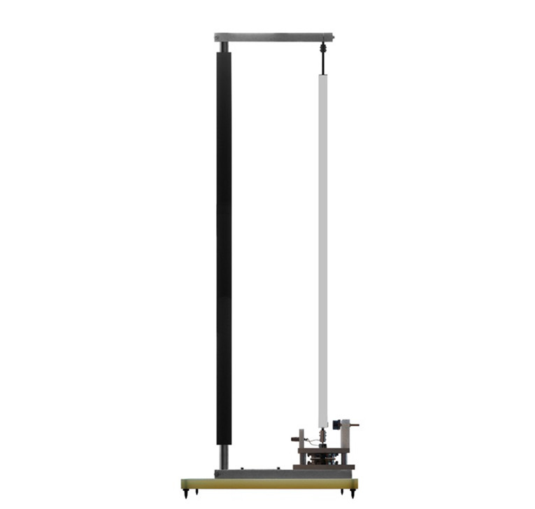
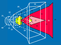
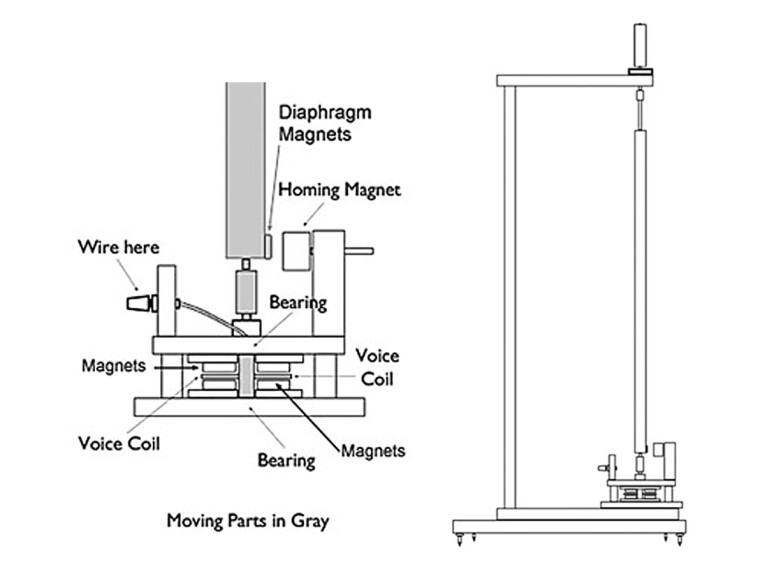
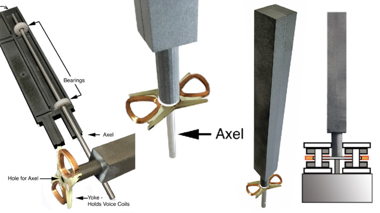
Because the diaphragm is centered by fixed bearings, the voice coil is always perfectly aligned to the magnets in the motor. The diaphragm is controlled by an electric motor that uses a magnetic repulsion system for centering and damping diaphragm movement in place of the traditional elastic surround/spider mechanism (Fig. 3).
According to Mr. Gaudreault, another major advantage of the Planot design is that sound is projected evenly in the listening area. The typical Planot diaphragm is long and thin and stands perpendicular to the floor with a motor in its base. The geometry allows sound at all frequencies to be launched into the listening area with equal energy and consequently with a very flat and even radiation in frequency and phase. A single diaphragm may be used, and the distortions and costs associated with crossover networks are eliminated. If greater dynamic range or greater sound levels for pro-sound applications are needed, then this same diaphragm can be implemented in multiway configurations such as two-way and three-way designs.
The Planot design also allows for the use of modular construction techniques. This way of connecting all of the components facilitates CNC (computer numerical control) construction, reducing production costs. Twin supports, mast, motor, and diaphragm may all be easily changed. There are several advantages to this approach: ease of manufacture, rapid prototyping, consumer upgrades, consumer customization, ease of repair, pro sound onsite assembly, and customization.
Again, according to the inventor, the Planot design can be utilized in many applications including but not limited to headphones, theater and auditorium systems, public address, high fidelity systems, portable electronic devices, automobiles, and boats. Planot, LLC, is currently soliciting interested manufacturers to license Gaudreault’s patented driver design. More information is available to OEM driver and loudspeaker manufacturers. VC
This article was originally published in Voice Coil, May 2011
Acoustic Patents
By James Croft, Croft Acoustical
Diaphragm for Full Range Boxless Rotary Loudspeaker Driver
Patent Number: US 7860265
Granted: December 28, 2010
Inventors: John Joseph Gaudreault (Omaha, NE)
Assignee: Self
Filed: July 30, 2007
US Class: 381/423, 1 Claim, 8 drawings
Abstract From Patent
The design of a diaphragm (Fig. 1) for a rotary loudspeaker driver that eliminates phase cancellation eliminates the necessity of a box to acoustically isolate the front sound from the back. The key element of the design of the diaphragm is to use a cross section of at least three equal sides. This allows for the long sides of the diaphragm to create essentially positive pressure only as it rotates and creates a very rigid structure. Further by sizing the cross section to the width of the highest frequency to be produced you allow for a nearly perfect 360° radiation at all frequencies.

Independent Claim
A diaphragm for a rotary loudspeaker driver that radiates sound at all frequencies in its range in a 360° horizontal pattern and can function as a full-range driver or can be implemented as a limited frequency range driver and that eliminates phase cancellation: (a) comprising the diaphragm structure with sides that have parallel and straight edges and the edges of each of these sides are parallel with the central axis of rotation, each of these sides being a simple rectangle, and the diaphragm’s cross section has at least three equal sides and is light and rigid (b) the diaphragm has a structure on both ends of its axis for attaching bearings and one or more electric motors to a rigid structure or frame (c) the diaphragm that has at least three sides and when rotated along its central axis creates a positive pressure in the surrounding medium on all sides parallel to the axis of rotation and is not subject to phase cancellation of front and back waves (d) the diaphragm in which the width of each side is equal to the width of the wavelength of the highest frequency that is to be radiated uniformly in the horizontal plane (e) whereby the diaphragm may radiate sound evenly at all frequencies within its range in a horizontal 360° pattern and vertically along its entire length.
Reviewer Comments
Disclosed is a new type of loudspeaker system architecture based on a rotary motor driving a three-sided diaphragm transducer. The transducer operates in free air, without a baffle and the “diaphragm” is shaped as an extended triangle with each of the three sides elongated to form a vertical line source with a horizontally omnidirectional wave front.
This diaphragm assembly rotates back and forth, clockwise/counter clockwise, similar to the oscillations of a washing machine. The inventor claims that the device has no phase cancellation and a perfect 360° horizontal radiation pattern. Rotary woofers have been developed in the past, most notably Danley U.S. 4763358 and U.S. 5140641, and Hisey U.S. 5825901, all of which are similar to this new invention, but the prior art devices are baffled and mounted in an enclosure, with isolation between the positive and negative wave fronts.
These devices had high acoustic output capability at low frequencies, but also suffered from restricted high-frequency bandwidth, noise problems, and substantial frictional losses. This new device eliminates the isolation baffle and enclosure, reducing noise and frictional losses; but it also removes isolation of the positive and negative wave fronts, operating similarly to a raw transducer in free air without enclosure or baffle.
The preferred embodiment of the new device had a diaphragm width of 3/4" on each of the three surfaces, and a height of 48". The notion of the inventor was to have the width of the diaphragm comparable to the wavelength of the highest frequency of interest. Claims for a device of this size were a high frequency extension of at least 18 kHz. There were no guidelines or parameters for what sets the low frequency capability.
The rotational movement of each of the three surface sides of the elongated triangle-form diaphragm, is such that half of the surface is rotating in a positive direction and half of the surface is pulling back in a negative direction, which would substantially cancel out low frequency response below a specific frequency relating the size of the diaphragm, creating a high-pass characteristic of 6dB per octave down to the resonant frequency of the transducer.
The good news is that the resonant frequency may be effectively very low, below 20 Hz, due to the design’s ability to incorporate very high rotational compliance. The inventor did not provide any measurements of the device, or even simulated performance, which is always a bit suspect in a patent, particularly when a device is this far off the beaten path and includes questionable attributes.
There are two aspects of this design that raise concern. First, the low frequency capability would appear to be self-cancelling, with the apparent opposite phases being radiated off of each diaphragm surface. Again, the fall-off rate is only a slow 6 dB/octave below the cutoff frequency, but that cutoff frequency may be well above 1 kHz for the given design example that is claimed to be a “full range” device.
A second issue is the phase variations off the diaphragm surfaces and what artificial spatial effects the device might exhibit. If one reviews the comments on the PlanotSpeaker.com website, both by the inventor and users of the system, they suggest that one can use a single device and still achieve a spacious sound field even in mono, with sound sources appearing far removed from the location of the device.
Some listeners even suggested being able to hear sounds coming from behind them. This would indicate that a rather severe phase anomaly is being generated by the system, which is consistent with an analysis of the wave launch characteristics of the rotational, open baffle diaphragm. A phase coherent line source should, when fed a mono signal, maintain a well-anchored and focused image.
There are some attributes that should be positive, such as the fact the diaphragm surfaces can be so small, it should be possible to have the diaphragm breakup modes be very well behaved. It should also be possible to make effective moving mass and moment of inertia quite small. The inherent ability for the system to be expressed as a seamless line source should have a good result.
It is clearly an interesting, innovative concept, but it remains to be seen as to whether it can be a practical device in terms of delivering lower frequency acoustic output and also whether it can project an accurate sonic image. I look forward to seeing some test results and hearing a demo. VC
This article was originally published in Voice Coil, August 2011
A Word from the Inventor
Because of its new geometry, the Planot driver can easily be implemented as a full-range omnidirectional driver. The Planot displays a very flat and smooth frequency response and is able to reveal improved reproduction at low power levels. The inventor is now looking to license the technology to manufacturers, and is able to deliver a significant number of documents, blueprints and full instructions on how to build functional prototypes. Plans for production include include 8 specialized tools to assist in building. A production design would be significantly simplified and inexpensive. Cost will vary according to material and tooling costs.
 Contact:
John J. Gaudreault
President, Planot, LLC
www.planotspeaker.com
Email John Gaudreault