Acoustic Filter for Omnidirectional Loudspeaker
Patent Number: 10,034,081
Inventor(s): Lakshmikanth Tipparaju (Valencia, CA); Allan Devantier (Newhall, CA); William Decanio (Valencia, CA); and Andri Bezzola (Pasadena, CA)
Assignee: Samsung Electronics Co., Ltd.
(Suwon-si, Korea)
Filed: April 28, 2016
Current CPC Class: H04R 1/288 (20130101)
Granted/Published: July 24, 2018 (expired)
Number of Claims: 20
Number of Drawings: 27
Abstract from Patent
One embodiment provides an omnidirectional loudspeaker comprising a phase plug and an acoustic resonator within the phase plug. The acoustic resonator comprises acoustic damping material.
Independent Claims
1. An omnidirectional loudspeaker, comprising: a phase plug comprising a base; a radiating surface positioned above and separate from the phase plug; and an acoustic resonator disposed within a portion of the base, wherein the acoustic resonator is at least partially filled with acoustic damping material, the acoustic resonator and the acoustic damping material combined attenuate sound at a frequency that is based at least in part on a physical characteristic of the acoustic resonator, and a portion of the acoustic resonator including a portion of the acoustic damping material is positioned in a path of sound propagation and protrudes into a cavity between the radiating surface and the phase plug.
12. A method for producing a phase plug for an omnidirectional loudspeaker including a radiating surface, comprising: identifying resonances in a cavity of the omni-directional loudspeaker to remove; and fabricating a phase plug for removing acoustic amplification generated by the resonances, wherein the radiating surface is positioned above and separate from the phase plug, the phase plug comprises a base including an acoustic resonator disposed within a portion of the base, the acoustic resonator is at least partially filled with acoustic damping material, the acoustic resonator and the acoustic damping material combined attenuate sound at a frequency that is based at least in part on a physical characteristic of the acoustic resonator, and a portion of the acoustic resonator including a portion of the acoustic damping material is positioned in a path of sound propagation and protrudes into a cavity between the radiating surface and the phase plug.
19. A method for removing acoustic amplification in a cavity between a diaphragm and a phase plug of an omni-directional loudspeaker, comprising: generating, utilizing a sound source of the omni-directional loudspeaker, sound; and removing acoustic amplification generated by resonances in the cavity utilizing the phase plug, wherein the diaphragm is positioned above and separate from the phase plug, the phase plug comprises a base including an acoustic resonator disposed within a portion of the base, the acoustic resonator is at least partially filled with acoustic damping material, the acoustic resonator and the acoustic damping material combined attenuate the sound at a frequency that is based at least in part on a physical characteristic of the acoustic resonator, and a portion of the acoustic resonator including a portion of the acoustic damping material is positioned in a path of sound propagation and protrudes into a cavity between the diaphragm and the phase plug.

Reviewer Comments
Over the years, there have been many loudspeaker systems wherein it has been advantageous to have at least one transducer deliver its acoustic output through a narrow aperture before radiating into the listening space. A few applications of this approach include: 1) slot loaded subwoofers; 2) speakers with a low-frequency driver coupled closely to a boundary surface in a listening room; and 3) omnidirectional loudspeakers with a 360° horizontal exit slot around the outside of the enclosure. The first application has been used to provide a specific load to the woofer, or to merely provide convenient packaging with a downward firing woofer system.
The second application has been suggested by Roy Allison in his 1974 Audio Engineering Society (AES) Convention paper “The Influence of Room Boundaries on Loudspeaker Power Output” and William Decanio in US Patent 2014/0334659 “Loudspeaker For Eliminating a Frequency Response Dip,” (see the January 2015 review in Voice Coil) assigned to Harman International Industries, as a means to eliminate cancellation due to boundary interaction. (William Decanio is now with Samsung and is one of the inventors of the current patent under review.)
The third application has been incorporated for decades, with many horizontally omnidirectional loudspeakers positioning the electroacoustic transducer such that it fires into a reflector with the acoustic output exiting a 360° slot.
While these structures have been useful for achieving their first level goals, for the most part they have all been plagued with cavity resonances in the waveguide between the driver and the environment external to the loudspeaker. These waveguide cavities create a series of resonances that often include a dominant peak that is on the order of 6 to 18 dB, plus additional amplitude cancellation effects in the response of the output. It tends to be impractical to attenuate this peak with a passive low-pass filter, particularly if it is near, or in, the system’s pass-band of the system.
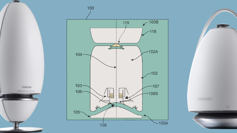
While the invention of this patent review could be effectively applied to all three categories discussed above, the focus of the invention is directed toward wide-band omnidirectional loudspeakers, and more specifically, is meant to be applied to Samsung’s new series of “Radiant360” R series (see Figure 1).
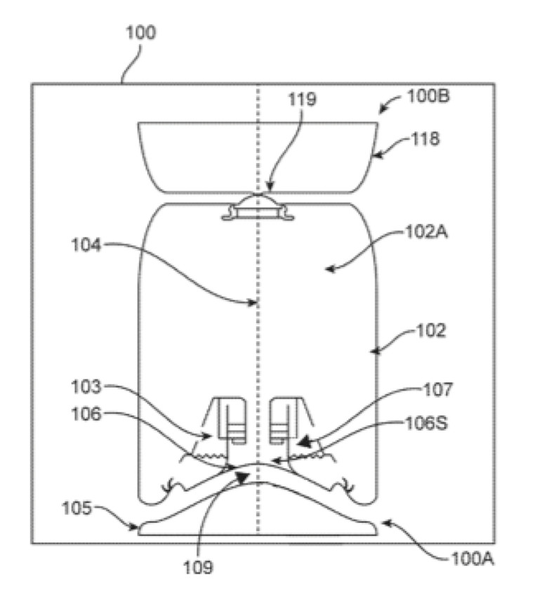
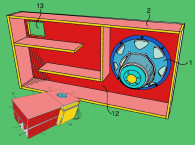
Addressing the problem of resonances created from 360° slot cavities, the invention discloses an omni-directional loudspeaker comprising a phase plug centered on the transducer and an omnidirectional waveguide. An acoustic resonator is placed within the phase plug and acoustic damping material is utilized in conjunction with acoustic resonator to control the ‘Q’ of the resonator. The resonator is optimized to absorb acoustic energy with the purpose of minimizing acoustic amplification, or cancellation, generated by the waveguide resonances.
Historically, a typical solution, particularly with active loudspeakers, has been to attempt to eliminate the resonances by way of active equalization. But, active “pre-equalization” is limited in this application due to a number of secondary issues that are not addressed by that approach. First, the resonances consist of amplitude peaks, and cancellation dips. It is most often not practical to attempt to equalize significant resonant cancellations due to the amplifier power requirements and transducer thermal and excursion stresses that may be required. Second, to paraphrase the inventors — active equalization is ineffective at removing resonances in the cavity because it attenuates a signal going into the loudspeaker at frequencies of the resonances in the cavity while the resonances in the cavity act as an acoustic amplifier that re-amplifies the attenuated signal to a desired level. Therefore, distortion components in a frequency region around the resonances in the cavity are amplified by the resonances but are not attenuated by the “pre-equalizer,” thereby negatively impacting the sound quality of the loudspeaker output. As with many cases of system resonance and distortion, this reviewer has found that, when possible, addressing the problem with “acoustical post-equalization” is often superior to “electronic pre-equalization.”
In some of the embodiments disclosed, the acoustic damping material, integrated into the resonant chamber, creates a physical acoustic filter that can attenuate more than one peak in the system output and the acoustic damping characteristics of the sound absorbing material can be used to match the Q-factor of attenuation to a Q-factor of resonance to also reduce dips in the amplitude response curves caused by resonances in the cavity. By way of the acoustic filter also reducing some of the acoustic phenomena that create dips in frequency response curves, the previously stated burden on the system, due to the active equalization increased power requirement, is minimized.
There are numerous configurations disclosed to achieve the desired result, all based on variations of the general concept of an acoustically damped cavity resonator.
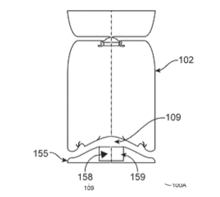
One approach, as shown in Figure 2, uses a simple cavity 159 directly across from the transducer diaphragm, on the opposite side of the waveguide channel. This cavity is filled to some degree with acoustic damping material 158. One implementation of this approach is configured as a cylindrical form, wherein the height is 28 mm and the diameter of the cylinder is 21 mm. The cylinder is filled with an unspecified density of damping material.
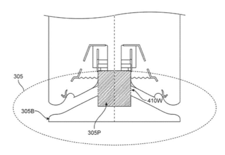
A second configuration is shown in Figure 3, wherein the resonant cavity 305P extends across the waveguide and through the center of the transducer diaphragm (sans dust-cap), extending inside the voice coil. The base/phase-plug 305B provides a support structure for one side of the waveguide and the acoustic filter comprising a resonator 305P filled with acoustic damping material. The resonant cavity 305P has a 360° peripheral perforated ring 410W.
A third configuration, shown in Figure 4, is configured as a Helmholtz resonant chamber, with the resonant frequency determined by the acoustic mass of cylindrical pipe 729 resonating with acoustic compliance volume 728. The opening of the Helmholtz resonator is flush with the side of the waveguide opposite of the transducer, and in this illustration the acoustic damping material impacting the ‘Q’ of the resonator is placed across the opening of the cylindrical pipe at the interface of the waveguide.
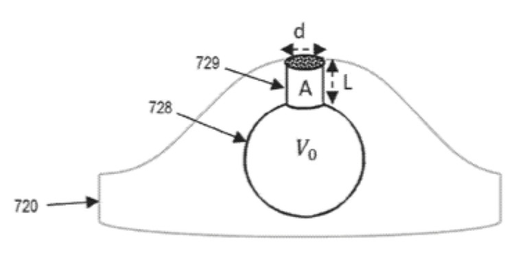
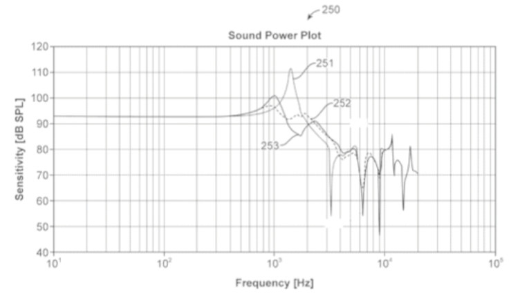
Figure 5 is an example graph illustrating multiple frequency response curves for two resonant chamber configuration examples, which shows a first frequency response curve 251 of the loudspeaker without a physical acoustic filter, a second frequency response curve 252 for the loudspeaker with a curve-shaped opening to the resonant absorber following the shape of the waveguide, and a third frequency response curve 253 for the loudspeaker with a flat-shaped opening to the resonant absorber at the interface to the waveguide. As demonstrated by the second and third frequency response curves 252 and 253, the resonant absorbers can be seen to not only reduce the magnitude of the primary peak but to also minimize or eliminate a number of the dips in a frequency response curve, thereby smoothing the passband amplitude response and extending the system’s useful bandwidth.
The inventive concept not only appears to be an effective solution to the specific application of Samsung’s omnidirectional sound systems, but it should also be a useful approach for resolving resonant cavity issues with various forms of acoustical apertures, including bass reflex ports, waveguides, and slot-loaded or boundary-coupled loudspeaker systems. VC
This article was originally published in Voice Coil, November 2018


