Electro Acoustic Driver
Application Publication Number: 20150146910
www.freepatentsonline.com/y2015/0146910.html
Inventors: Daniel Beer (Martinroda, Germany); Lutz Ehrig (Dresden, Germany); Lorenz Betz (Wassertruedingen, Germany); Philip Leistner (Stuttgart, Germany); Karlheinz Bay (Stuttgart, Germany); and Michael Leistner (Stuttgart, Germany)
Assignee: Fraunhofer-Gesellschaft zur Foerderung der angewandten Forschung e.V. Munich, Germany
Filed: March 8, 2013
US Class: 381/398
Published: May 28, 2015
Number of Claims: 32
Number of Drawings: 14
Abstract from Patent
Independent Claims
- 1. An electro acoustic driver, comprising: a diaphragm; a diaphragm drive system configured to subject the diaphragm to a motion; and a diaphragm suspension configured to guide the diaphragm; wherein the diaphragm suspension comprises an active element and/or piezo electrical element configured to actively influence the motion of the diaphragm.
- 24. An electro acoustic driver, comprising: a diaphragm configured to move in a direction of a piston-like motion; and a surround formed along an edge region of the diaphragm so as to guide the diaphragm laterally and along the direction of the piston-like motion, wherein the surround is configured to actively excite the piston-like motion.
- 28. An electro acoustic driver, comprising: a diaphragm configured to move in a direction of a piston-like motion; a basket; a diaphragm drive system arranged between an edge region of the diaphragm and the basket, wherein the diaphragm drive system comprises one or more electrical devices which are configured to subject the diaphragm to a piston-like motion; and a diaphragm suspension configured to guide the diaphragm laterally and along the piston-like motion.
Reviewer Comments
Disclosed is an electroacoustic transducer with several variations with most examples consisting of one of two configurations.
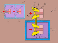
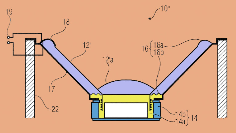
The first configuration (shown in Figure 2C from the patent application) includes a diaphragm and a diaphragm drive system, such as a standard dynamic voice coil and magnetic circuit, arranged to activate the diaphragm to vibratile motion and a diaphragm suspension configured to connect the diaphragm to the transducer frame. The diaphragm suspension incorporates a piezoelectric active element configured to actively control the diaphragm’s motion.
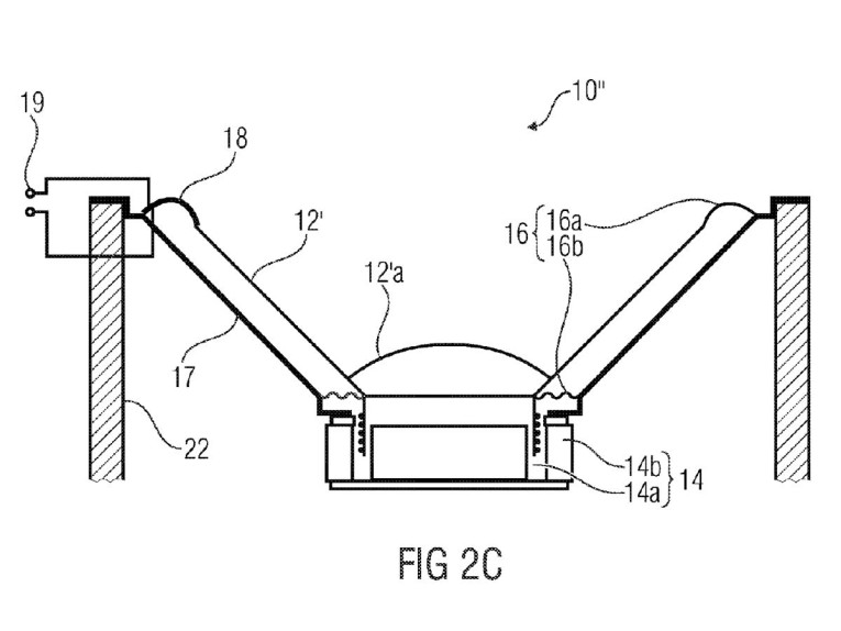
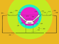
The second configuration includes a diaphragm and a diaphragm drive system, arranged to activate the diaphragm to vibratile motion and a diaphragm suspension configured to connect the diaphragm to the transducer frame. The diaphragm suspension incorporates a piezoelectric active element configured to provide the primary drive to the diaphragm.
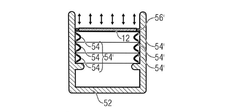
A variation on the second configuration uses multiple piezoelectric suspensions in series to increase the drive to, and excursion of, the diaphragm (as illustrated in Figure 6A from the patent application).
The approach of the present invention is driven by the notion of the inventors that the primary nonlinearities of a transducer output are typically caused by nonlinearities in the diaphragm suspension itself (i.e., by the spider and/or the surround).
To compensate for these mechanical nonlinearities at their source, the diaphragm suspension comprises one or more active piezoelectric elements. These active elements are said to enable the “active suspension” to exercise an influence on the linearity of the transducer, by way of electromechanically compensating for variations in compliance and resistance within the suspension system over the range of excursion.
Besides the distortion caused by the nonlinear restoring force within the suspension, further nonlinearities caused by a magnetic field of the drive system of an moving-coil loudspeaker or caused by external conditions, such as temperature effects, or by aging of the transducer components may also be reduced by using the active suspension as a means for adaptive correction.
It is stated that configurations that integrate the diaphragm suspension and the diaphragm drive system into one unit are done to reduce the complexity of the transducer’s structure, having a single point of drive and linearity correction.
In the embodiment that has both a conventional electromagnetic motor and also the corrective piezoelectric elements in the suspension, a separate drive signal must be provided to the suspension and it is derived from a sensor that detects the nonlinearity and provides the corrective signal.
It is stated that the control signal may be predicatively deduced from the audio signal, for example by processing the audio signal by using a lookup table. Alternatively, the control signal may be based on a sensor signal output by a sensor for determining nonlinearities of the diaphragm or for determining the transmission characteristic of the diaphragm suspension. The driver may include a sensor coupled to the diaphragm suspension or the diaphragm such as a piezoelectric element formed by one of the active elements or a Hall effect device, which is configured to measure the magnetic field based on which nonlinearities are detectable. Such sensors may drive a processing unit configured to output the control signal for the active corrective device based on the sensor signal.
Alternatively, it is stated that the sensor may be implemented as a network comprising a plurality of sensors, and a processing unit, configured to process the different signals of the sensor and outputting the control signal for the active corrective devices.
The patent does not contain any measurements illustrating a reduction in distortion when using the inventions. Neither is there any data on the general performance of the invention. While the expansion and contraction type piezoelectric elements that would be used in this type of configuration can exert substantial force, they tend to be limited to very small ranges of movement. This would lead one to question whether the active suspensions based on the disclosed structures would have adequate range of motion to sustain effective corrective action over the range of excursion displaced by transducers that exhibit suspension nonlinearities to the degree that correction would be desired. Additionally, for the embodiments that the piezoelectric elements also provide the primary drive to the diaphragm, it is questionable as to whether they can provide the excursion capabilities that would be competitive with a standard electromagnetic motor.
If the piezoelectric elements could be configured to operate effectively over the full range of excursion then it may be possible to optimize the system to achieve a level of nonlinear correction. Ultimately, one would have to consider whether any distortion caused by the suspension and magnetic circuit in a given transducer might be more effectively addressed by designing for an improvement in the linearity of each of those elements directly. Conceptually, the invention is certainly noteworthy and it will be interesting to see if it can be refined to the point of offering a superior result. VC
This article was originally published in Voice Coil, September 2015.