Pop and zipper noise when changing gain on digitally controlled mic preamps is now simple to eliminate, using the hybrid gain control (HGC) feature of Cirrus Logic’s new CS530xP family of Pro Audio ADCs. This pop and zipper noise is a long-standing challenge for designers of pro-audio gear. Existing solutions for fine-resolution mic preamp gain control, with the feel of a traditional potentiometer but without audible pops or zipper noise, are often expensive and complex. HGC solves this problem by integrating control of the mic preamp gain into the ADC, together with zero-cross detection and precisely synchronized digital gain control. HGC makes it easy for pro-audio product designers to assure smooth pop-free gain control, while retaining their existing mic preamp design and simplifying both hardware and software.
Digital Gain Control of Mic Preamps
Historically, the mic preamp gain on analog pro-audio products such as mixing consoles was controlled by a potentiometer. The advent of digital audio mixing consoles created a need for mic preamp gain to be digitally controlled. Digital control enabled mic preamps to be located remotely from the control surface of the mixer. In turn, this enabled valuable new product architectures that replaced the heavy analog multi-core cables strung around studios and performance venues with thin, light network cables carrying digital audio. Digital gain control also allowed mic preamp gain settings to be stored and recalled under software control. It is now a ubiquitous feature of mixing consoles and is increasingly featured in other pro audio products such as recording interfaces for laptops.
This digital gain control is most often implemented using analog multiplexers to switch different gain-setting resistors into the mic preamp circuit. The user interface on the control surface is typically a rotary encoder. Sound engineers still expect this “gain knob” to respond with the continuous gain response of a potentiometer. To achieve this, control software manages a digital “interpolation gain” applied after the ADC to interpolate between the analog gain steps. As the sound engineer turns the gain knob clockwise, the switched mic preamp gain increases in steps, while the digital gain interpolates smoothly between those steps (Figure 1).
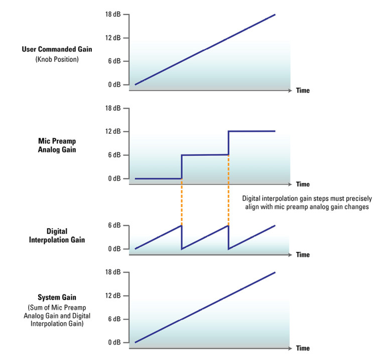
When the analog gain increases by a step, the digital gain must simultaneously decrease by the same amount to maintain a smooth gain increase. The analog and digital gains sum to produce the system gain, which should be the same as the gain commanded by the knob.
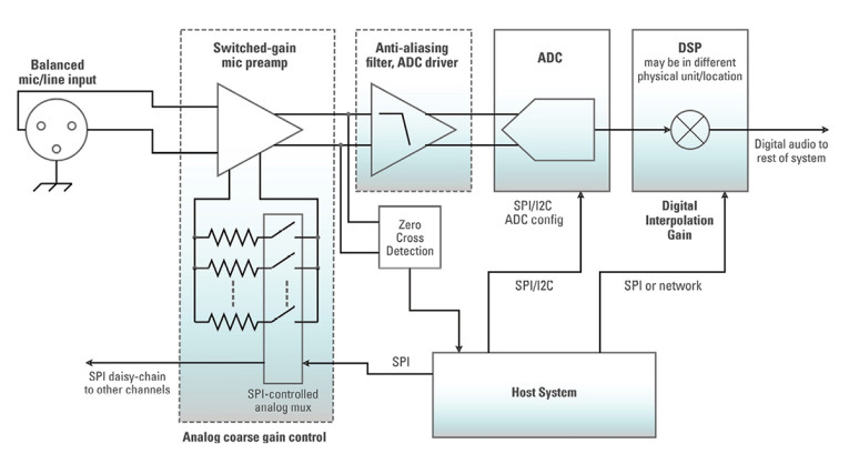
To minimize pop noise on changing gain, the analog gain changes may also be aligned with the analog signal crossing the signal zero-level point. This ensures that the gain change occurs when the signal amplitude is zero, to avoid the gain change causing audible transients. A typical system implementing this scheme, without HGC, is illustrated in Figure 2.
Implementing Digital Control of Mic Preamp Gain Is Tricky
Pro audio product designers over the years have encountered various problems and complexities with implementing the kind of scheme for digital control of preamp gain depicted in Figure 2.
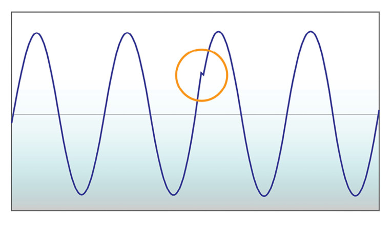
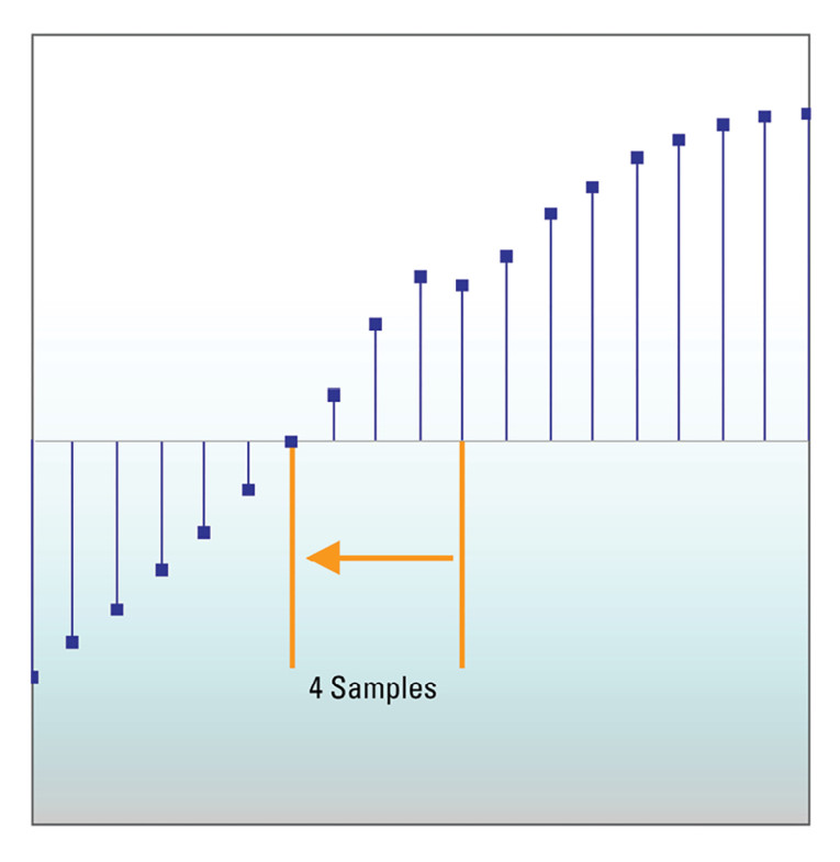
Perhaps the biggest difficulty is that the digital interpolation gain is usually implemented in the audio system’s DSP. This is often in a different part of the system to the mic preamp, and system constraints can make it difficult to achieve precise synchronization between analog gain changes and digital interpolation gain steps. Timing misalignment between these operations may cause audible transients, as illustrated below by misconfiguring Cirrus Logic’s HGC demonstration hardware. These figures show a gain change comprising an analog +3dB increase and a -3dB digital gain step on a 1kHz sine wave. The analog gain change is simultaneous with the zero-crossing point, but the matching digital gain step is 4 samples (about 83µs) late. This causes a glitch visible in the waveform (Figure 3 and Figure 4) and is clearly audible.
Another difficulty is that the system illustrated in Figure 2 is complex. It includes discrete circuitry for analog zero-cross detection to align analog gain changes with zero-crossing to minimize transients. If omitted, the pop and zipper noise is much worse, such that the audio channel may need to be temporarily muted when changing gain. The system also needs multiple control paths from the host. If the DSP and the analog input path are under the control of two separate communication processors, distributed host software must manage the state of the system gain split into two components, each located in different computing nodes. This can introduce substantial software complexity.
One potential solution is to use a Multiplying DAC (MDAC) instead of the switched-resistor gain selection. This gives high-resolution, pop-free gain changes, but MDAC devices may be too expensive for many pro audio products. Alternatively, more multiplexer paths with more resistor combinations can give smaller step sizes to approximate continuous gain control, but that also increases cost and complexity, and may degrade audio performance.
In short, implementations of digitally controlled mic preamp gain have tended to be either susceptible to pop/zipper noise on gain changes or have incurred high cost and complexity to mitigate the pop/zipper noise.
Cirrus Logic CS530xP Makes Pop-Free Gain Control Easy
Cirrus Logic’s new CS530xP family of Pro Audio ADCs introduces HGC, which greatly simplifies pop-free digital control of mic preamp gain. HGC achieves this by integrating into the ADC chip several elements of the legacy system shown in Figure 2.
A configurable daisy-chain SPI controller configures the gain of up to eight mic preamps. Each ADC channel features an analog zero-cross detector to synchronize pop-free analog gain changes. Each ADC signal path includes a digital gain control to implement the interpolation gain emulating the continuous control feel of a potentiometer. HGC logic coordinates operation of all the above functions to execute precisely synchronized, glitch-free gain updates. The resulting simplified system architecture with HGC is illustrated in Figure 5.
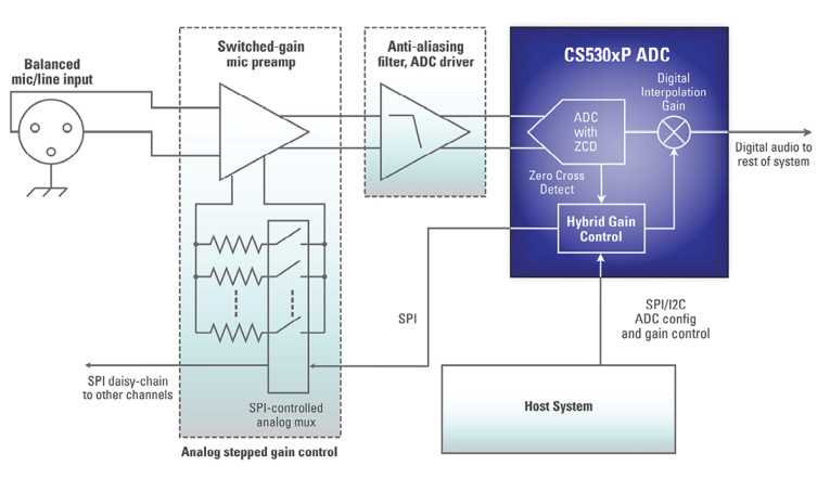
When the user turns the gain control knob on the control surface, the host software writes registers in the CS530xP to configure and request a mic preamp gain change. This causes HGC to control the mic preamp, via SPI, to set the desired gain change. This is precisely aligned with an analog zero-crossing. Since HGC also has control over the digital audio signal path, it precisely aligns the digital gain change with the analog gain change. This precise alignment of analog and digital gain changes with a zero-crossing ensures a pop-free gain update.
The states of the analog gain and digital interpolation gain are both located in the registers of the CS530xP HGC block, under the control of the one host processor controlling the ADC.
Compared to the legacy system illustrated in Figure 2, the HGC system has simpler hardware for a smaller bill-of-materials, simpler software and creates less pop/zipper noise on gain changes.
How Hybrid Gain Control Works
The sequence of events for a gain change with HGC is illustrated in Figure 6. A gain change is initiated by the host software writing to the HGC registers to configure and trigger the gain update. This causes the HGC SPI interface to send the gain bit patterns to the daisy-chain of mic preamps, to configure one of them for the newly commanded gain value (point 1 in Figure 6). The gain bit pattern depends on the design of the mic preamp.
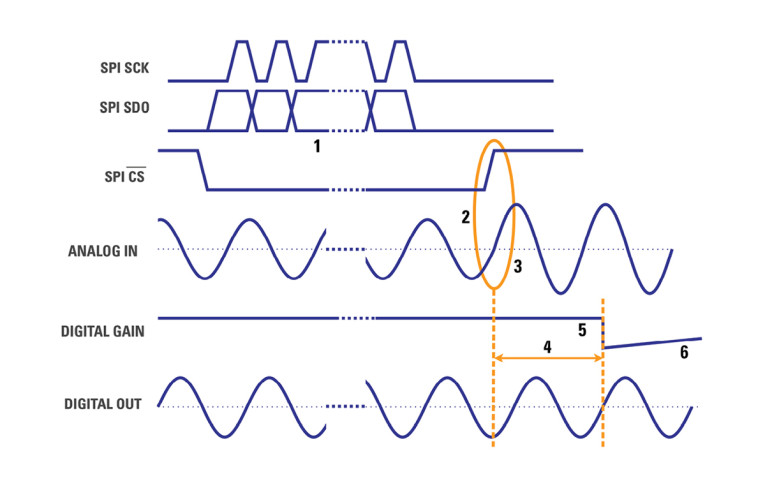
After the HGC SPI interface has shifted the gain bit patterns into the mic preamps, the SPI CSb signal remains asserted low until a zero-cross is detected on the channel that is changing gain (point 2 in Figure 6). This causes CSb to be de-asserted, which causes the new gain code to take effect in the mic pre-amp, which in turn causes an instantaneous zero-cross-aligned gain change in the analog signal path (point 3 in Figure 6).
After the gain change, HGC waits a short configurable duration (typically 4-8 sample periods, point 4 in Figure 6) to compensate for the signal path latency from the mic preamp, through the analog anti-aliasing filter, ADC, and decimation filter.
At this point, HGC executes the precisely timed digital gain step (point 5 in Figure 6), to counteract the analog gain change. It then commences a gain ramp to the final fine-gain value (point 6 in Figure 6). Ramping the gain over tens of milliseconds avoids introducing audible transients.
Achieve Pop-Free Operation with Existing Mic Preamp Designs
For some pro-audio product designers, the design and sonic characteristics of their mic preamp is a crucial brand asset and a differentiating feature. HGC allows product designers to achieve pop-free operation with their existing mic preamp designs. Any mic preamp design may be used if it complies with just three simple requirements:
- Has stepped gain control. Gain steps do not need to be equal sized, and it may have any number of gain steps of any values.
- Gain must be controllable by daisy-chain SPI, such that the gain can be changed by writing one SPI bit pattern into its daisy-chain SPI shift register, of any length between 1 and 32 bits per mic preamp. The encoding of SPI bit pattern to gain value is completely configurable in HGC.
- Gain change must take effect immediately on de-asserting SPI CSb at the end of the daisy-chain SPI operation.
A simple and compact implementation is to use daisy-chainable SPI-controlled analog multiplexers to switch different value resistors into the mic preamp circuit. Alternatively, a standard logic shift register such as the 8-bit 74HCS595 may be used with daisy-chain SPI to give static logic outputs in a manner similar to a port expander, which in turn may control analog multiplexers or directly control discrete transistors.
HGC supports mic preamp gain control for each channel of the ADC (up to eight channels, in the case of the Cirrus Logic CS5308P). It also includes control of up to 64 bits of additional SPI daisy chain devices, through the same SPI interface the mic preamp gains. These can be used for control of auxiliary hardware functions associated with the input paths, without requiring extra microcontroller I/O or serial interfaces. Applications include switching +48V phantom power, enabling an analog high-pass filter, controlling LEDs by the input connectors, or switching between balanced and unbalanced inputs.
Easy to Control from Existing Software Architectures
Control of gain changes with HGC is similar to existing schemes, in which both analog gain and digital interpolation gain are computed and set by the host software. This means that the host software modifications required to use HGC are typically minor and of limited scope. To command a HGC gain change, the host software writes four pieces of information to the HGC registers of the CS530xP ADC chip:
- Gain selection bit pattern: The pattern of SPI bits to set the mic preamp to the selected analog gain setting, according to the design of the preamp.
- Analog gain: The absolute analog gain value corresponding to the new bit pattern for the selected mic preamp, to the nearest 0.125dB.
- Digital gain: the value of the digital interpolation gain required to achieve the system gain set by the user, to the nearest 0.125dB.
- Gain update signal: Indicates that the three items above have all been written, such that HGC may now execute the synchronized gain change.
As with prior digital gain control implementations, the algorithm to choose which analog gain step to select for a particular system gain request is implemented in host software, according to the system designer’s preference for managing dynamic range.
The analog gain register fields are used to determine the difference in mic preamp analog gain between the previous setting and the new setting. This difference is used to determine the size and direction of the digital gain step, to counter the analog gain step before the digital gain is ramped to the new value specified in the digital gain field.
The host may command a gain change at any time, and it is guaranteed to be executed within a time bound of approximately the number of active channels multiplied by the zero-cross timeout configuration setting (20ms maximum). In practice, with real-world audio signals it is likely to execute much faster than that due to audio zero-cross detection.
HGC Solves a Long-Standing Design Challenge
HGC on Cirrus Logic’s CS530xP family of ADCs, and other forthcoming pro audio products, makes it easy and inexpensive to implement digitally controlled mic preamps with smooth, quiet gain changes without pop or zipper noise. This resolves a long-standing design challenge with implementing digital control of mic preamp gain, which until now has presented pro audio product designers with a difficult trade-off between frustrating pop and zipper noise on gain changes, or high complexity and larger bill-of-materials (BOMs).
HGC makes it easy to achieve these benefits with existing switched-gain mic preamp designs and is easy to control from existing host software architectures. It simplifies hardware design for mic preamp gain control, including integrated control for auxiliary functions such as phantom power, signal path relays, or LEDs. This new capability is conveniently integrated with state-of-the-art ADC performance of 123dB dynamic range and at least -110dB THD+N, at a power consumption of just 25mW/channel (Cirrus Logic CS5308P).
HGC enables the premium user experience of potentiometer-like digital mic preamp gain controls, with no pop or zipper noise, to be delivered across all pro audio product tiers at an affordable cost. aX
www.cirrus.com
This article was originally published in audioXpress, November 2023