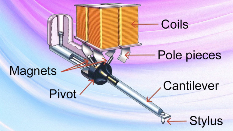
A moving magnet (MM) cartridge can be considered as composed of two important parts, a (removable) Cantilever Assembly complete with stylus, suspension, and attached magnets and a Voltage Generator receiving the cantilevers signal through magnetic induction, hereafter indicated as generator. The overall frequency response or transfer curve (TC) for the complete MM cartridge can be recorded for several load schemes with calibrated test disks; let’s call this transfer function FR1.
Its voltage generator’s electrical properties can also be measured with a Vector Network Analyzer (VNA), accurately up to several megahertz, also resulting in a TC; let’s call that FR2. Subtracting FR2 from FR1 will result in the TC of the cantilever assembly FR3. By translating FR3 into an electrical equivalent diagram, it will be possible to further investigate this TC and understand the factors leading to its properties.
With all the input of the noted measurements, the goal of this article is to find out whether the mechanical and the electrical part are “seeing” each other or can be regarded as independently operating parts.
This article was originally published in audioXpress, December 2024 and is now Available to Read Online Here.