Improving Electrodynamic Loudspeaker Reproduction
There are many ways to improve the linearity of the process of sound generation of a loudspeaker chassis. Usually a zero-output impedance amplifier (a.k.a. Voltage Drive) is used — one amplifier for the loudspeaker box, or dedicated amplifiers for each chassis — and this results in a certain closed-loop control of the sound output. The current through the voice coil is determined by the difference of the voice coil applied voltage and the voice coil velocity back induced voltage divided by the loop impedance. The movement (i.e., velocity of the voice coil) significantly determines its driving current, which closes the feedback loop.
To further improve the quality of the electro-acoustic transfer function of a loudspeaker chassis some manufacturers have modified the amplifiers‘ output impedance. From a negative impedance nearly compensating the positive voice coil resistance and getting more control through the back induced voltage, up to infinite output impedance (a.k.a. Current Drive), which completely eliminates the effect of the back induced voltage.
However, as the generation of the membrane acceleration, which is proportional to the SPL, is already a nonlinear process and the resulting generation of the back induced voltage is a further nonlinear process, approaches with zero or negative output impedance have limited effect. In contrast Current Drive completely eliminates the effect of the back induced voltage and adds no harmonic and intermodulation distortion.
The next logical step in improving the electro-acoustic transfer function of a loudspeaker chassis uses a feedback system (a.k.a. Motion Feedback or MFB). The membrane or voice coil movement is measured and compared with the electrical input signal. Provided highly linear sensors for the measurement are used and sufficient loop gain of the control loop is available, the nonlinearities of a chassis can be reduced to an inaudible level. We will see that motion can be characterized by each of the physical properties: membrane excursion, membrane velocity, or membrane acceleration.
Motion Feedback for Loudspeakers
As an example, Figure 1 displays the frequency responses of the sound pressure level (SPL) and the harmonic distortions k2 and k3 of a woofer in free air under current drive conditions. It is obvious, that for frequencies about three times above the resonance frequency the harmonic distortions k2 and k3 are about 65dB below the fundamental frequency. These excellent values can also be achieved in a closed box with Current Drive [1].
The prominent resonance of the chassis under Current Drive conditions can easily be equalized by a Pole-Zero Compensation [2]. However, below the resonance frequency the generated force of the motor acts less against the constant moving mass, but much more against the highly nonlinear compliance (i.e., the surround and the spider). This is the reason for the growing nonlinearity and the increasing harmonic distortions visible in Figure 1. Based on this observation, a simple rule of thumb is proposed: When a chassis is operated above three times its resonance frequency, a further linearization by motion feedback is not required as long as the chassis is of adequate quality. Operation below this limit requires motion feedback in case one wants to maintain the high linearity and low levels of harmonic and intermodulation distortions.
A well-engineered motion feedback system eliminates the original resonance of the chassis and extends its frequency response to arbitrarily lower frequencies (e.g., to 16Hz), the lower limit of the human auditory system [3]. In addition, harmonic and intermodulation distortions are reduced to below 60dB with reference to the fundamental frequency.
Motion Feedback Strategies
When selecting a motion feedback system there are three fundamental considerations involved:
- The target of a control concept for loudspeakers is to linearize the transfer function of the electrical input to sound pressure output of the transducer on one hand, and to achieve a linear sound pressure frequency response on the other hand. We will see that these two requirements are not necessarily fulfilled simultaneously.
- Physics tells us that the membrane acceleration is the time derivative of the membrane velocity, which in turn is the time derivative of the membrane excursion [4]. Control concepts for loudspeakers can use (measure and control) any of these physical properties.
- Physics also tells us that because of the rising acoustical impedance by 20dB per frequency decade in the frequency range of interest, the velocity of the membrane needs to decrease accordingly to achieve a constant sound pressure frequency response [5]. That can be achieved by keeping the membrane acceleration constant over frequency.
Using an acceleration sensor results in a constant control loop frequency response.
Using a velocity sensor results in a single differentiation of the control loop (its frequency response rises with 20dB/frequency decade).
Using an excursion sensor results in a double differentiation of the control loop (its frequency response rises with 40dB/frequency decade).
Consequently, these three sensor types require (in the described sequence) no, a single, or a double integration as linear pre-distortion of the audio signal feeding the control loop. Otherwise, one would linearize the loudspeaker but not have a constant frequency response. A single integration of the audio signal costs 20dB, a double integration costs 40dB of dynamics per frequency decade. A required linear pre-distortion is a certain disadvantage against a direct acceleration-controlled loudspeaker.
Membrane Excursion Control Loop
Usually, capacitive sensors are suggested. One of the most prominent examples, which was in production for many years [7] used a capacitive sensor for the tweeter. In fact, the tweeter acted simultaneously as a condenser microphone whereby the full membrane area was used. Instead of using the voltage of the condenser microphone as output signal, its capacitive current was used. This type of sensor is well suited for tweeters, but less for woofers because of the large travel distances at low frequencies and high SPLs. A capacitive sensor for a woofer is proposed in the “Capacitive Motional Feedback for Loudspeakers” article [8]. Here the area and thus the capacity of the sensor capacitor is changed proportional to the excursion of the voice coil.
A general disadvantage of all capacitive sensors lies in the high voltages up to 250V, which are required. Humidity can especially lead to audible current discharges. Other sensors have been suggested (e.g., Hall sensors), but to the best of my knowledge they have never been commercialized in a product. As the control loop differentiates twice, the linear pre-distortion needs to integrate twice to get a constant SPL frequency response.
Membrane Velocity Control Loop
The velocity sensor is in principle a dynamic microphone whereby its membrane is substituted by the loudspeaker membrane. One of the most prominent examples, which is in current production [9] uses an additional magnet system in the axis of the loudspeaker magnet system and a dedicated sensor coil fixed to the voice coil former. A patent [10] describes the realization of the necessary pick-up coil as a multi-layer printed circuit. The sensor is susceptible to magnetic interference from, for instance, transformers, but also from the voice coil current.
There are solutions to compensate for those stray fields, but a lot of engineering experience is required to realize this control concept successfully. The control loop differentiates once and needs the integration of the audio signal as linear pre-distortion at its input to get a constant frequency response. A sensor-less version of this strategy uses the voice coil induced voltage as velocity signal. This technology was used for many years [11] by using slightly different magnets (i.e., different Bl-products) for two electrical identical chassis working in the same enclosure. In this way it is possible to extract an approximate velocity signal.
A further sensor-less version of this strategy measures voltage and current of the chassis. For example, at constant current, the voltage of the chassis is the difference between the complex voltage generated by the equivalent electrical elements of the chassis and the velocity induced voltage.
Again, it is possible to extract an approximate velocity proportional signal. However, both sensor-less versions suffer from the fact that the transfer function between voice coil current and membrane acceleration is already nonlinear and largely the same nonlinearities are present again in the generation process of the velocity induced voltage (varying Bl product, nonlinear compliance …).
By measuring the voice coil voltage and current one can adjust a model for the nonlinear pre-distortion of the chassis with a certain update rate [12]. Since this is not a real-time control loop and is based on a nonlinear pre-distortion, this article will not discuss real-time controlled loudspeakers.
Membrane Acceleration Control Loop
Acceleration sensors can now be procured as a microelectromechanical system (MEMS) sensor with high linearity, low noise, and sufficient acceleration range [13]. The advantage of MEMS acceleration sensors is their immunity against electrical and magnetic interference. These sensors are available with 0.1% linearity, which translates to the linearity of the overall control loop provided sufficiently high loop gain is available. These sensors use tiny spring-mass systems etched in silicon with an active capacitive read-out.
One of the most prominent examples using modern MEMS sensors, which is in current production [14], uses Analog Devices’ MEMS sensors and achieves 0.1% distortions and a perfect constant SPL frequency response from 15Hz up to the upper limit of the used chassis. An alternative is a piezo-electric sensor consisting of a thin Piezo film on a spring/mass system [15]. Products with this type of sensor have previously been on the market [16].
A general problem with all acceleration sensors is their principle based on a spring/mass system with usually low damping. As long as the resonance frequency of the spring/mass system is sufficiently above the control loop upper band limit this is a manageable issue. A potential issue for absolute acceleration sensors is their susceptibility to the gravitational acceleration and physical movements of the loudspeaker box. So, don‘t move the loudspeaker around if the control loop is active, or the membrane will try to stay at its original position! As the acceleration sensor results in a control loop with constant frequency response, the control loop does not need linear pre-distortion. The MEMS sensor may be more costly than other sensors, but it is a highly accurate and simple to use device not requiring any adjustment.
Example Control Loop Architecture with MEMS Sensor Acceleration Feedback
Figure 2 shows the block diagram of a modular integrated solution comprising the power amplifier and the complete control loop electronics [17].
The frequency characteristic of the analog controller provides a high loop gain centered at the resonance frequency of the chassis. Peak loop gains between 40dB and 60dB can be achieved. From the peak the loop gain falls with increasing and decreasing frequency with 20dB/frequency decade, thus determining the upper and lower loop gain limits (0dB) and ensuring stability of the control loop. To adapt to a different driver chassis, the loop gain can be adjusted by a 12-turn potentiometer.
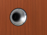
The highly linear DMOS power amplifier completes the forward chain. The feedback sensor is mounted inside the voice coil and its signal closes the control loop. All other blocks ensure the protection of the chassis and of the amplifier and take care of inaudible transition between standby, mute, and operational states.
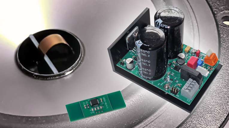
The MFB monitoring and protection system is based on a microcontroller, which is also responsible for automatic calibration of the offset of different MEMS sensors and to null the gravitational acceleration in case the chassis is not operated in a vertical orientation. STBY and MUTE are bidirectional control signals allowing synchronization of multiple amplifiers. Photo 1 shows the necessary elements of the described acceleration feedback system, while Photo 2 shows the mounting of the sensor PCB inside the voice coil and its lead-out flatcable.
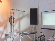
One has to keep in mind the inverse-square law [18]. Half the frequency leads to a fourfold membrane excursion at constant acceleration. All chassis are in practical terms limited by the maximum (linear) membrane travel at low frequencies, not by the available membrane acceleration. Measurements are performed with the AudioChiemgau ModeCompensator to compensate the room modes in the laboratory.
Figure 4 shows the harmonic distortions of the chassis, which remain 60dB below the fundamental frequency. Below 40Hz the second harmonic shows a 20dB per frequency decade increase toward lower frequencies. The reason for this is Doppler distortion (a.k.a. Phase Modulation) of the moving membrane, which generates beneath the Bessel spectral lines also a second harmonic.
Figure 5 shows the SPL frequency response referenced to the acceleration signal, which is the mechanical-acoustical transfer function between membrane acceleration and generated sound pressure. This transfer function is perfectly constant within the measurement accuracy up to 200Hz, where the beaming of the relatively large membrane becomes visible.
In Conclusion
Three real-time systems for MFB of loudspeakers were discussed with respect to their advantages and disadvantages. Two of the concepts are currently used by high-end manufacturers [19, 20]. Considering the simplicity of the application in the practical world, the direct acceleration-controlled loudspeaker (i.e., using an acceleration control loop) seems to be favorable, even when the MEMS sensor has its cost. AudioChiemgau offers ready-to-use modules for high-end acceleration-controlled loudspeakers. aX
Resources
R. Lutz, “Measuring Loudspeaker SPL Response and Harmonic Distortion at Low Frequencies,” audioXpress, October 2023,
References
[1] “Comparison of Voltage Drive and Current Drive of a Woofer – Effect on Sound Quality,” AudioChiemgau, https://audiochiemgau.com/voltage-vs-current
[2] V. Saxena, “Indirect Feedback Compensation Techniques for Multi-Stage Operational Amplifiers, Pole-Zero Analysis of Multi-Stage Amplifiers,” October 2007, https://cmosedu.com/jbaker/students/theses
[3] H. Kuchling, Taschenbuch der Physik, 15. Auflage. Verlag Harri Deutsch (auch VEB Fachbuchverlag Leipzig), Thun u. a. 1991, ISBN 3-8171-1020-0, 23.2.1 Hörfläche, S. 337.
[4] R.G. Lerner; George L. Trigg (1991), Encyclopedia of Physics (Second Edition), New York, VCH Publishers, ISBN 0-89573-752-3. OCLC 20853637.
[5] M. Zollner and E. Zwicker, Elektroakustik: Mit 62 durchgerechneten Beisp, (Springer-Lehrbuch), ISBN: 9783540646655
[English translation: Electroacoustics: With 62 Numerical Examples, (Springer)]
[6] “Control Engineering,” Wikipedia, https://en.wikipedia.org/wiki/Control_engineering#References
[7] “Capacitive sensor for loudspeakers,” German Patent DE2419447C3
[8] “Capacitive Motional Feedback for Loudspeakers,” spasi.nuutinmaki@servospeaker.com
[9] “Capacitive Feedback,“ German Patent DE2422232A1
[10] Backes & Müller Patentschrift, DE 10 2015 102 643 A1 2016.08.25
[11] Backes & Müller BM3, HIFI WIKI, www.hifi-wiki.de/index.php/Backes_&_Müller_BM_3
[12] “Klippel Controlled Sound,” Klippel, www.klippel.de/products/klippel-controlled-sound.html
[13] “Low Noise, High Frequency MEMS Accelerometers, ADXL1001/ADXL1002,” Analog Devices MEMS Sensor datasheet,
www.analog.com/media/en/technical-documentation/data-sheets/ADXL1001-1002.pdf
[14] “ADXL1001Low Noise, High Frequency ±100g MEMS Accelerometer,” Analog Devices Datasheet, www.analog.com/en/products/adxl1001.html
[15] Piezo Electric Sensors, Metra Mess- und Frequenztechnik, https://mmf.de/iepe_standard.htm
[16] “Phillips RH 532 MFB Loudspeaker, HiFi Engine, www.hifiengine.com/manual_library/philips/rh532.shtml
[17] AudioChiemgau, www.audiochiemgau.de
[18] “Inverse Square Law,” Wikipedia, https://en.wikipedia.org/wiki/Inverse-square_law#References
[19] Silbersand, www.silbersand.de
[20] Backes & Müller, www.backesmueller.de
This article was originally published in audioXpress, March 2024