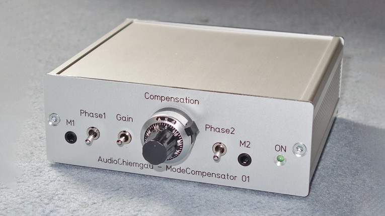
When we received Dr. Reinhold Lutz’s article proposal, we were surprised that we hadn’t previously heard of the ModeCompensator. Most audioXpress readers will be familiar with the issues of trying to make a good, reliable measurement of low-frequency response and distortion in loudspeakers and drivers. One of us has even been paying user fees for the local university’s anechoic room to do such measurements.
MLS excited low-frequency measurements or close mike low-frequency measurements and splicing that response to the mid/high response to get an audio band response are known techniques. Swept measurements need careful attention to finding a compromise in windowing the impulse response to exclude reflection without throwing away valuable low-frequency response information. So, naturally we were quite curious to find out if a simple, low-cost unit like the ModeCompensator would take care of all that, so we asked for a sample and decided to do a basic functional test.
The Setup
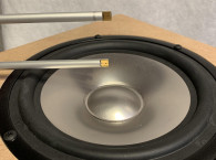
We set up the unit with the two microphones as described in the User Guide using a guitar amp woofer on a baffle as shown in Photo 1.
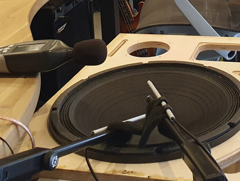
The two microphone outputs were connected to the inputs of an Audio Precision APx525. After the setup, we connected the ModeCompensator difference output to one of the AP inputs and conducted the measurement sweep. All traces (individual mikes and the difference output) were recorded in the same graph for comparison. Initially, we couldn’t get it to work as it should. We would do the measurement run and then using the AP time domain measurement adjust the precision dial on the unit for a minimum at the difference output. We just got some low-level chaotic curve.
After some communication with Dr. Lutz, we realized our procedure was incorrect. You do not want a perfect subtraction of the two curves to zero output. Consider, mike 1 has as output: V(c) + V(a&m), while mike 2 receives: V(c/2) +V(a&m) where V(c) is the direct signal from the driver cone, and V(a&m) is the signal resulting from ambient noise and room modes. When you correctly subtract those two levels you get V(c/2), not zero! Obvious in hindsight, but since this is a very unusual unit, this could be explained more clearly in the User Guide [1]. In the end, we chose an attenuator setting very close to the factory-recommended setting, which is provided for each unit.
Does It Work?
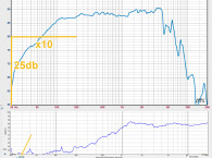
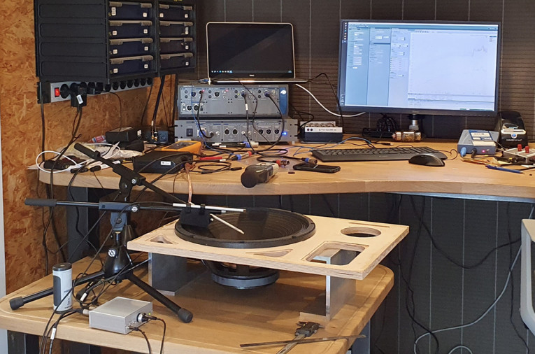
To start with the conclusion: Yes, it definitely does work. The idea behind it is sound, and we could reliably measure the low-frequency response of the woofer with almost no ambient noise or room reflections visible. But let us put it in perspective, with Figure 1. The top and bottom curves are measured by the two microphones, and we see some low-frequency noise and minimal reflections below 80Hz or so. More reflections and modes can be seen up to 300Hz. If you look at the difference response (middle curve), you see that the difference processing has neatly canceled those ripples and produced a nice smooth frequency response for this woofer. We were surprised that we did not see more reflections and modes below 100Hz, as shown in Dr. Lutz’s article elsewhere in this issue. Our measurement space wasn’t particularly large or damped and had ample angles and edges to cause reflections (Photo 2).
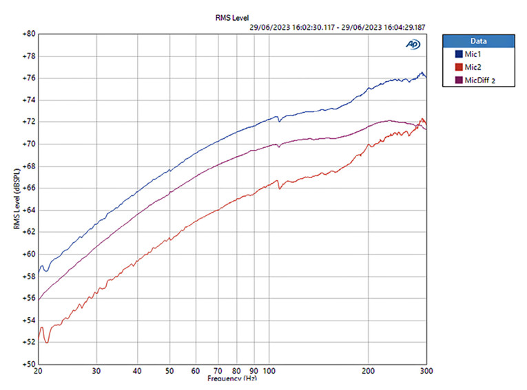
But there’s one more aspect to this. We did our measurements at a relatively low SPL. We found that the ripples and modes were a bit more pronounced at low levels. The positive side of that is that you can do these measurements without having to grab the hearing protection all the time, and even without disturbing fellow workers close by. Especially in a production environment, that is a great plus.
The Verdict
We met a lot of skepticism from colleagues when we mentioned an article and review of this unit, varying from “it won’t work” to “nobody needs that.” But being sure that resonances and ripples seen in the driver response do not come from ambient noise and room modes is a valuable result. There’s also the substantial advantage of being able to do these tests at very low levels without losing information. So, we feel that, especially at the reasonable cost of around $500 including a pair of calibrated electret microphones, this is a useful unit if you routinely do low-frequency woofer or speaker measurements. For more information, visit https://audiochiemgau.com/modecompensator-01
[1] With the measurement microphone 5cm above the cone, and the mode mike 5cm above the measurement mic, the mode microphone receives half of the cone level see the User Guide from the AudioChiemgau website, https://audiochiemgau.com.
Lutz, Reinhold - Measuring Loudspeaker SPL Response and Harmonic Distortion at Low Frequencies, audioXpress October 2023.
This article was originally published in audioXpress, October 2023


