Outside of the enthusiast niche (of which I freely admit to belonging), these are all dead issues. Not that they are fully understood and agreed upon by those chasing ultimate measured performance well beyond any questions of audibility, but that they are analogous to arguments over the best way to print a scale on a slide rule. Class-D amplification has taken the non-hobbyist market by storm. Though it’s become a cliché to say, “The D in Class D does not mean ‘digital,’ it was just the next letter after C,” it is not far from the truth to note that the D could just as easily stand for “disruptive.”
Class D (a method of pulse width modulation, PWM) is not a new concept but it laid fallow for many years with only a scattering of commercial attempts to implement PWM circuitry in audio amplifiers, most notably by Infinity and Sony. But starting about a decade ago, the commercialization of Class-D amplifiers has gone from slow and sporadic to warp speed. The advantages are compelling, notably much higher efficiency (90% or higher), meaning smaller, lighter, and cooler packages, and freedom from artifacts such as crossover distortion and gm doubling inherent to conventional Class-AB amplification.
Enthusiasts have grudgingly admitted that Class-D amplification has improved over the years, but the mantra was always, “It’s improving, but they’re not there yet.” Of course, the performance bar to compete, not just sonically but also in the performance numbers wars, has been raised following years of analytical work and improvement by makers of Class-AB amplifiers. One example is the superb Cambridge Audio Edge W that I reviewed a few months back (see Resources), which had astonishingly low distortion and noise, and seemed to drive any load I threw at it with ease and imperturbability.
Two Class-D amplifiers — the Orchard Audio BOSC (meanwhile renamed Starkrimson) and the Purifi Audio Eigentakt EVAL1 — spent some time in my listening room and on my lab bench and represent how close to perfection this technology has come. Each has innovative design features and performance well past any question of audible perfection and both packaging and power that deliver on Class D’s promise. They take very different approaches to achieving high performance — one unit using novel devices, the other using novel topologies. I will consider each of these separately.
Orchard Audio BOSC / Starkrimson Monoblocks
As we were going to press, we were informed that due to a trademark dispute with Bosch, the BOSC amplifier was renamed Starkrimson. This article was updated in its online version replacing most of the original BOSC references to Starkrimson.
For those on the cutting edge of high-efficiency power conversion, the semiconductor gallium nitride offers huge potential advantages compared to conventional silicon (see Resources). Although GaN has found wide application in optoelectronics, its use in power conversion and audio applications is much more recent. Compared to silicon, the electron mobility in GaN is higher, the temperature coefficient is lower, and the higher band-gap compared to silicon means a lower degree of thermally generated charge carriers when the devices heat up.
Translating these characteristics into application advantages, the higher charge mobility means that the substrates can be smaller, which means lower capacitances. Lower capacitances reduce switching time, allowing a higher switching frequency.
Additionally, GaN’s conduction does not involve minority carriers, so the reverse recovery charge (QRR) is essentially zero, a significant advantage over conventional MOSFETs in reduction of dead-time and increase of switching frequency. Dead-time is the portion of the cycle where both output devices in a totem pole arrangement are switched off to prevent “shoot through,” where the two power rails get shorted by the RDS(on) of the output devices.
GaN transistor producers claim that the reduction in dead-time correlates with a reduction in harmonic distortion due to the output devices controlling the load through a greater portion of the signal cycle. The lower dead-time and higher carrier mobility should also increase efficiency, all other things being equal.
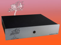
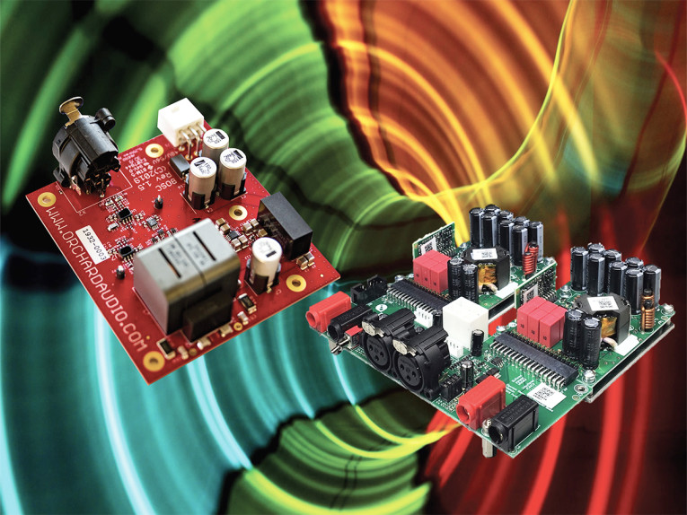
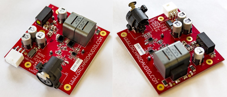
Lower threshold voltages reduce drive requirements. And a faster switching frequency should theoretically be better suppressed by the output low-pass filter. How does this work in practice? Enter Orchard Audio, the audio company run and staffed by Leo Ayzenshtat, an aerospace engineer who has specialized in PCB design. Orchard’s initial products were a series of USB-based DACs available in different configurations (PCB-only for OEM, in a case with a headphone amplifier, and with and without streaming options). Recently, Orchard introduced the Starkrimson power amp (see Photo 1), a 150 W monoblock module with a separate power brick.
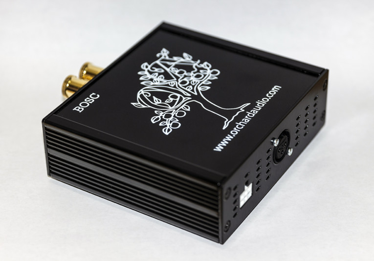
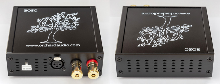
The Starkrimson is supplied in a rather plain black box with extruded side panels. The company name and logo are silkscreened in white on the top. Each monoblock has its own external power brick, which is actually somewhat larger and heavier than the amplifier module. The inputs are balanced XLR, and Orchard supplies XLR-to-RCA adapters for those whose systems are run strictly single ended. The speaker binding posts are sturdy and gold-plated.
They accommodate bare wire, spade, and banana plugs, and are, I’m delighted to say, spaced at a standard 0.75” apart. It should be noted that the outputs are differential. For the vast majority of systems, this is no issue, but beware if you have a headphone adapter or speaker switch-box that uses a common ground between channels.
The nominal gain can be selected at the time of purchase at 16.8 dB (A = 6.92) or at 13.8 dB (A = 4.89), meant for 8 Ω and 4 Ω nominal impedance speakers, respectively. This is much lower than a typical home audio power amp gain of 26 dB or so, so don’t be surprised if you have to crank up your preamp volume knob. If your preamp or source is rated for a 2 V output, you might have to either add a gain block or replace them with units having a higher output.
Also, the Starkrimson’s input impedance is rather low, at 5 kΩ and 7 kΩ, respectively, for the two gain options. Most modern sources will have no trouble driving it, but older gear or tube sources could huff and puff a bit. On the output side, the damping factor is claimed to be 550, which translates to a commendably low-source impedance of about 15 mΩ. The value will be swamped by any practical speaker cable and certainly by speaker voice coil resistances.
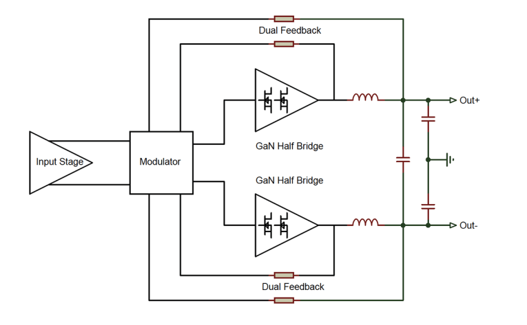
The Starkrimson amps’ circuit is based on a proprietary dual feedback self-oscillating design (see Figure 1). The amplifier is balanced and differential from input to output with fully bridged GaN output stages. According to Orchard, the output LC filter, which is used to covert the PCM output of the bridge to an analog signal, is a critical element in determining the sound quality of a Class-D amplifier. To this end, the BOSC amplifier uses what they term as “oversized ultra-high-quality Japanese inductors wound with oxygen-free copper, specifically made for Class-D amplifiers.”
The capacitor used in the output filter is a film capacitor, which Orchard says is sized larger than needed to help keep the amplifier’s distortion very low through the whole powerband, and also help keep temperatures lower as efficiency increases. Presumably, the capacitors in this circuit position were also selected for low equivalent series resistance (ESR) to minimize heating and increase reliability.
The amplifier’s higher-than-usual switching frequency combined with the output filter design is intended to result in minimal phase shift below 30 kHz. The amplifier is DC coupled, which minimizes phase shift at very low frequencies as well. Orchard claims that this results in a better-controlled bass response from loudspeakers.
The diagram also shows what Orchard calls a “dual feedback” system. The feedback to the pulse width modulator is taken differentially from both the half-bridge output and the speaker output, that is, from both sides of the output filter. The intention here is to minimize the effect of the output filter on the amplifier’s response and distortion performance within the audio band.
Since the amplifier is DC coupled, it will also amplify any DC on its input, so be careful when pairing these amps with sources that have direct-coupled outputs.
Purifi Eigentakt 400 Amplifier Demonstration System
As previously discussed in audioXpress (see Resources), Purifi Audio is a Danish company founded by some of the best minds in audio. One of the notable partners is Bruno Putzeys, who has done more than just about anyone else to refine Class-D technology to performance levels that would be nearly impossible to achieve with conventional linear amplification.
The high audio performance is coupled with the high efficiency and the small size for which Class-D amps are noted. Following his successes with UCD and nCore amplifiers, he and his collaborator, Lars Risbo, accepted the challenge to take amplification in general to new performance levels, and to do so in a way that didn’t destroy the superb economics of the previous generations.
A key to this is using extremely high amounts of feedback, which Putzeys explained nicely in an article a few years back (see Resources). Negative feedback lowers distortion and reduces output impedance, but applying large amounts is tricky to pull off while maintaining amplifier stability.
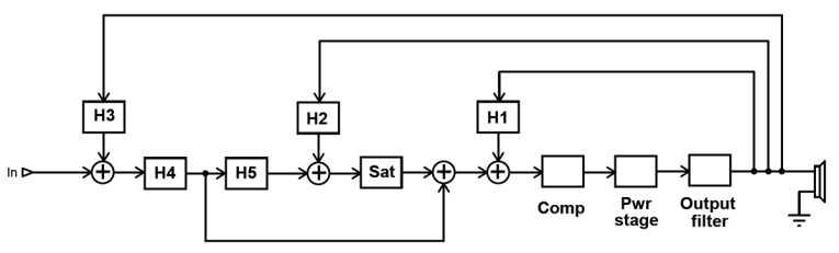
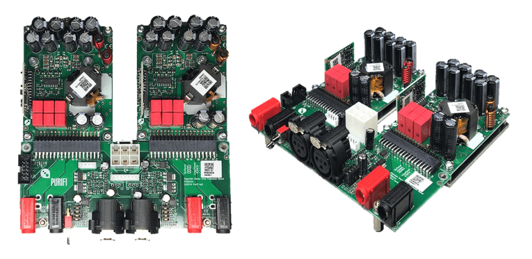
Figure 2 shows a block diagram of their amplification scheme. The various “H” blocks represent active or passive circuits with tailored transfer functions. For example, if a “classical” Class-D amplifier is represented by the combination of the comparator, the switching output stage, the output filter, and the feedback system H1, the amplifier can be nested within a secondary set of loops, which would include H2, H3, and their respective summing amplifiers, along with feedforward from filters H4 and H5, plus the compensator.
It’s clear that there are a LOT of knobs to turn (metaphorically), and optimization of the overall system for flat response, low distortion, wide bandwidth, and unconditional stability is a rather daunting proposition. To this end, Purifi developed a sophisticated proprietary computer modeling system that can juggle all of the variables to reach a design target. I would highly recommend reading the patent applications referenced in Resources to get a good idea of the sophistication of Purifi’s approach.
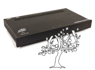
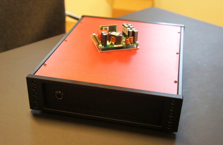
Purifi has released its 1ET400A OEM 400 W (4 Ω, 1% distortion) mono amplifier modules for manufacturers and DIYers to integrate into complete products. To demonstrate their performance, Purifi sent me its EVAL1 evaluation system, which consists of two 1ET400A modules and an FE02A front end system with all the analog input and the control circuitry needed to form a working stereo amplifier (see Photo 3). For review convenience, this particular demo unit was packaged with a power supply and in an aluminum case with I/O connectors, though these are not included in the normal EVAL1 system (see Photo 4).
Integrators have the option of using the FE02A or developing their own proprietary input circuitry. The bare 1ET400A module has a gain of 12.8 dB (A = 4.4), which combined with the FE02A input module’s selectable 0 dB (actually bypassing the input amplification) or 13 dB gain results in an overall power amplifier gain of 12.8 dB (low) or 26 dB (normal). The input module, when not bypassed, also has a buffering function, increasing the input impedance from 4.4 kΩ of the bare 1ET400A to just under 100 kΩ, which in conjunction with the 26 dB overall gain can be driven by nearly every conceivable source.
So, how do these two different approaches end up working for the user?
The First Test: Listening Room
Before measuring the Orchard Starkrimson (I only had it for a few weeks, so I put it on the lab bench first), I hooked both the Starkrimson and the Purifi amplifiers up in my system. Currently, I am using a biamped setup in my lab, with speakers based on the classic NHT 3.3 four-way dynamics, but with modified crossovers and cabinet volumes. These speakers represent a relatively non-brutal but typical load (nominally 6 Ω), but are not terribly efficient at about 87 dB/watt/1 m. Crossovers are electrically a fourth-order Linkwitz-Riley (LR) low pass for the woofers and a second-order Butterworth high pass for the rest of the drivers, to achieve an overall fourth-order acoustic LR crossover at 110 Hz.
The electronic crossovers were, at different times, a Didden-modified Behringer DCX2496 (with the active option) and a miniDSP 2x4HD. Both of these units allowed me to adjust relative gains between the woofers and the rest of the drivers (mid-woofer, midrange, and tweeter). When using the Didden/Behringer, the amps were connected in balanced mode. When using the miniDSP 2x4HD, I used RCA-to-XLR adapters to drive the amps in unbalanced mode. Neither crossover has any difficulty with loads in the impedance range of the Starkrimson amps’ inputs.
I switched the amplifiers’ positions between driving the woofer and driving the rest of the drivers several times over the course of two weeks of listening and use tests. Now, it is no secret that I believe an amplifier’s job is to make a small signal larger—things like “conveying the emotion of music” are, in my view, best left to the musicians and producers. So the best amplifier is one that has no sound of its own.
For both of these amplifiers, regardless of where they were inserted in my system, I could discern no difference in the sound, nor was there any difference compared to some pretty fine conventional linear amplifiers that I’ve used recently. No matter what sort of music I played — from acoustic jazz to Americana-folk to electronic progressive rock, whether my own minimally miked uncompressed recordings or highly produced loud studio rock — the amplifiers did exactly what they were supposed to, noiselessly, without stress or strain, and in a perfectly transparent way. Some might complain that this reduces the role of amplification to mere appliances—that’s fine with me, I want to listen to music, not to my amplifier.
I should also note that neither amplifier got anything close to hot, even after extended listening sessions at brisk volumes. This is of particular importance to hot climate area dwellers like me, but also suggests higher reliability.
The Starkrimsons on the Bench
After using these amps for a few weeks, I predicted that there would be nothing unusual or alarming in the measurements. Unfortunately, because of the very short length of time I was able to keep the Starkrimsons, my measurements aren’t comprehensive, but I think they are sufficient to back up my listening impressions.
As usual, my test setup comprises an Audio Precision APx525, though I briefly pressed an APx555 B Series into service. Later on (unfortunately after the Starkrimsons had to be returned), I had access to a very low distortion 1 kHz sine wave source (Vicnic) and a tuned twin-T notch filter, which extended my 1 kHz distortion measurement capability. Using the “bare” APx-525 as a signal source and analyzer, my distortion measurement capability extends down to about -115 dB below the signal level, dominated by the third harmonic. Dummy loads were variously 8 Ω, 4 Ω, and a simulated loudspeaker load (this load simulates a closed-box system with a 50 Hz fundamental resonance and a crossover at about 3 kHz), all mounted on large heatsinks to minimize thermal modulation.
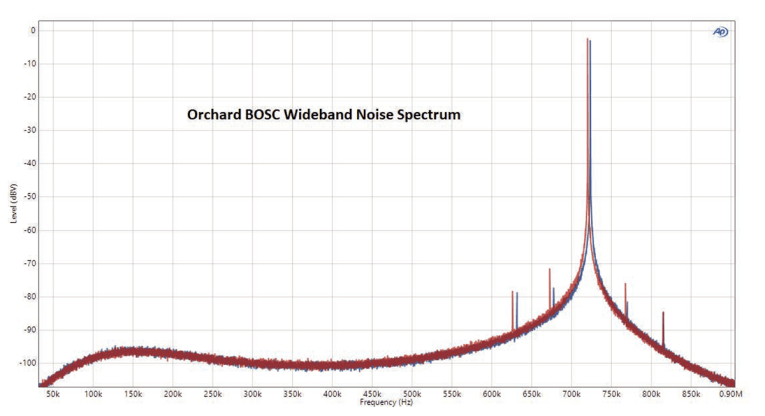
I’ve seen much angst and dark implications about the ultrasonic noise output of Class-D power amps, so I routinely measure them for this characteristic. Figure 3 shows the no-signal output spectrum of the Starkrimson amps with an 8 Ω load connected. The ultrasonic noise floor is low, never exceeding -95 dBV (18 μV) except near the switching frequency of about 720 kHz, where it rises to about -3 dBV (710 mV).
These noise results seem absolutely inconsequential, and you can see the noise floor drop further as the frequency goes down to the audio range. Measuring the audio frequency noise for a 24 kHz bandwidth, the total noise was 46 μV for the worse channel, slightly higher than specification but still well below any reasonable worry. To put this in perspective, if you have a very efficient 100 dB/2.83 V/meter horn, this translates to an SPL of 4 dB at 1 meter, which might be barely audible to a toddler in an anechoic chamber. Maybe. As a practical matter, I couldn’t tell if the amps were on or off when my ear was inches away from my speakers.
Besides full power measurements, amplifiers are often measured at low power, traditionally to bring out the effects of non-ideal behavior (e.g., crossover distortion), and in recognition that for most musical signals at most reasonable listening levels, the amplifier will not be putting out anything close to its rated power. Even though this isn’t likely relevant to Class-D amps, I bow to tradition.
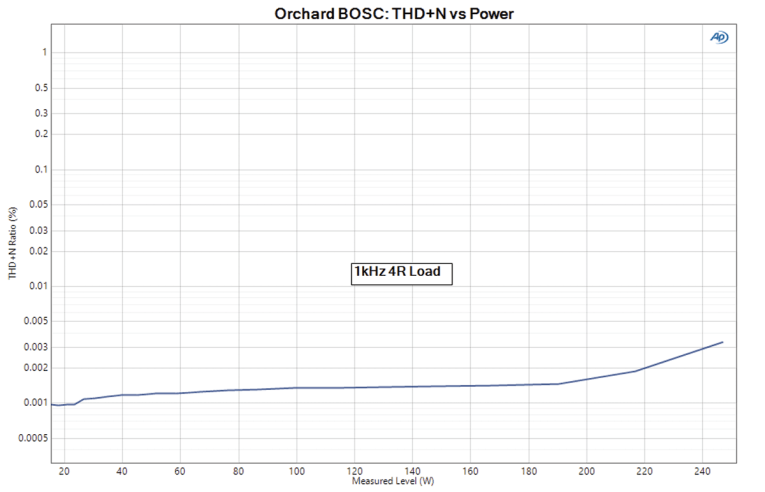
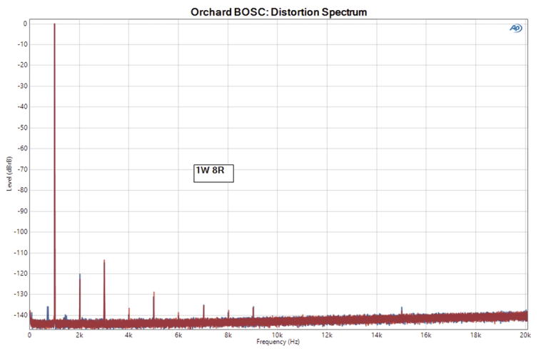
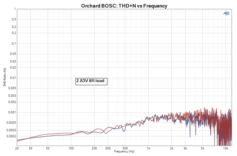
Figure 6 shows the distortion spectrum for a 1 kHz signal at 2.83 V into an 8 Ω load (1 W). It is dominated by the residual distortion of the AP analyzer, which is extremely impressive! Sweeping the frequency at the same fixed 2.83 V output level, the total harmonic distortion plus noise (THD+N) results are shown in Figure 7, and are likely dominated by the noise. In any event, any distortion is well below 0.001%, so it’s safe to declare it inaudible.
Enter the Purifi EVAL1
Next on my test bench was the Purifi Audio EVAL1 system. Purifi’s 1ET400A datasheet (see Resources) has a very comprehensive set of measurements, so rather than repeat all of them, I checked the main ones (which all checked out) and added a few other measurements.
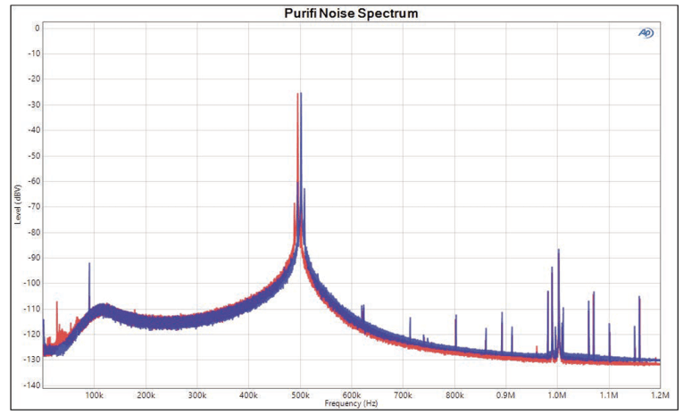
First, the basics: gain of the system was 27.45 dB, slightly higher than specification. As with the BOSC, the gains were very tightly matched between channels, within 0.05 dB. Input impedance measured about 95 kΩ differentially. The no-signal noise spectrum is shown in Figure 8, and indicates a 500 kHz switching frequency at about 0.2 V, which is inconsequential.
The ultrasonic noise floor is likewise quite low with the largest component being a spur at -93 dBV at 90 kHz. This is low enough not to disorient bats passing by. I proceeded to perform some measurements at moderate and high power. The 100 W 19+20 kHz intermodulation distortion (IMD) spectrum is shown in Figure 8 for an 8 Ω load (in red), and the sidebands are below -115 dB, with the main IMD product of 1 kHz below -125 dB. Substituting the simulated speaker load (in blue), the distortion actually drops slightly, though at these minuscule levels, the differences are academic.

The distortion spectrum of a 1 kHz sine wave at a moderate level of 20 W into the 8 Ω load is shown in Figure 9; the light red curve is generated using the AP analyzer alone and is below the analyzer’s residual. Using the low distortion Vicnic oscillator and a twin-T notch filter with 55 dB of fundamental suppression, it can be seen (green curve) that the amplifier’s distortion is below -140 dB (0.00001%), which is… astounding, and proof that the limitation here is indeed the AP analyzer, not the amplifier.
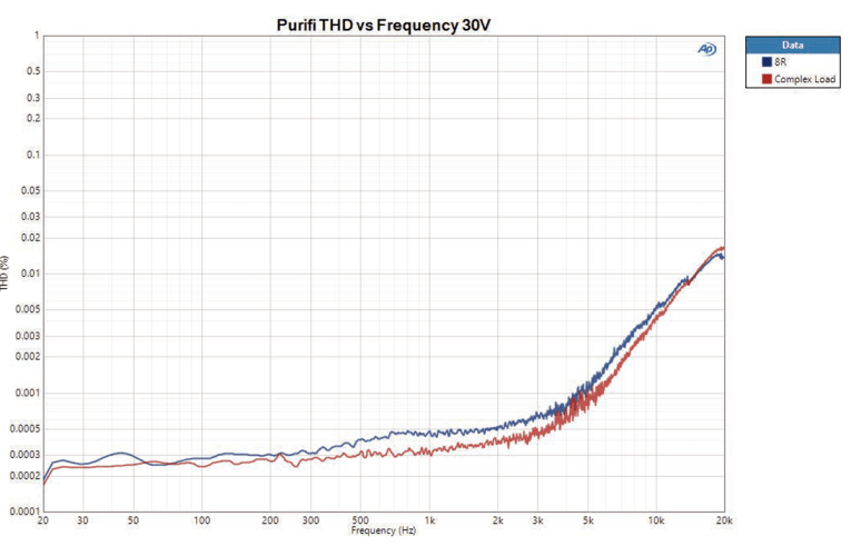
The source impedance was below my ability to measure, but looking at the frequency response differences when substituting the simulated speaker for the resistor load, the frequency response change was less than 0.01 dB. This amp’s sound will not be affected by the loudspeaker’s impedance. THD vs. frequency at 2.83 V is shown in Figure 10 for the 8 Ω and simulated speaker loads—there’s no significant difference. Repeating the measurement at 30 V (112 W into 8 Ω), I obtained the results shown in Figure 11, where we can finally see a small rise in distortion in the top octave, but still below 0.02% and relatively unaffected by load.
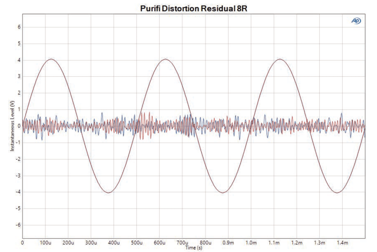
Figure 12 shows a 2.83 V sine wave at 1 kHz, along with the residual magnified by 1000. It’s clearly dominated by noise, with no visible glitches or harmonics. These are essentially perfect measurements.

Earlier in the article I used the term “appliance,” and really it’s the best way I can think of amplification here in the year 2020. Both of these amplifiers ran cool, mechanically quiet, noise-free, and basically... unexciting. And that’s the highest compliment I can give to electronics that are intended to be transparent.
For integrators or those who want to experiment with front-end design, the Purifi is the clear choice. For someone who just wants an amplifier to run the stereo, one of the many integrated versions of the Purifi or (if going for separates) the Orchard BOSC will do pretty much equally well — and by “well” here, I mean “superbly.” Special system requirements (e.g., common grounding between channels) or just a non-sonic esthetic choice (e.g., look, feel, reputation) might sway a prospective purchaser in one direction or another, but soundwise, either is essentially perfect.
Any measurement differences seen here fall orders of magnitude below human hearing thresholds. This does raise a philosophical question in my mind — where do we go from here? Although audibly transparent amplification capable of driving most loudspeaker loads has been available for decades, we now can do it at a relatively low price, high power, compact, cool, with vanishingly low distortion and source impedance, and with efficiencies in the 90+% range, well past diminishing returns. Could it be time to declare victory and go home? Or just admit that the only thing left to do is to scale upward and downward in power? Is this analogous to Francis Fukuyama’s “End of History”? Personally, I’m certainly leaning toward making amps such as the Purifi or Starkrimson the last ones I’ll ever own. aX
Author’s Acknowledgements: I’d like to thank the kind people at Orchard Audio and Purifi for providing product photography and technical support, and Jan Didden for laboriously drawing the block diagrams.
This article was originally published in audioXpress, July 2020.
This online article was updated replacing most of the original BOSC references to Starkrimson.
References
BOSC/Starkrimson — 150W Hifi Monoblock GaN Audio Amplifier:
https://orchardaudio.com/bosc
S. Colino and R. Beach, “Fundamentals of Gallium Nitride Power Transistors,” EPC Application Note AN0002, available at:
https://epc-co.com/epc/Portals/0/epc/documents/product-training/appnote_ganfundamentals.pdf
J. Didden, “Purifi Audio: A Straight Wire to the Soul of Music,” audioXpress, September 2019,
O. Masciarotte and S. Yaniger, “Cambridge Audio Edge W Power Amplifier,” audioXpress, January 2020.
J. Martins, “Purifi Audio: A Conversation About Amplifiers and Speakers.”
Purifi, “1ET400A Datasheet, v 1.00,” https://purifi-audio.com/wp-content/uploads/2020/01/1ET400A-Data-Sheet-1.00.pdf
Purifi, “EVAL1 User’s Guide,” available at: https://purifi-audio.com/wp-content/uploads/2020/01/EVAL1-Users-Guide-1.20.pdf
B. Putzeys, “Simple Self-Oscillating Class D Amplifier with Full Output Filter Control,” Audio Engineering Society 118th Convention, Barcelona, Spain, 2005.
www.researchgate.net/publication/268383069_Simple_Self-Oscillating_Class_D_Amplifier_with_Full_Output_Filter_Control
B. Putzeys and L. Risbo, “An Amplifier With a Compensator With a Network of At Least Third Order,” Patent application WO2019110154A1; “An Amplifier With a Compensator With a Network of At Least Second Order,” Patent application WO2019110153A1; “Amplifier Circuit,” Patent application WO2019110152A1.