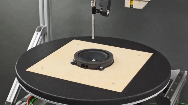
The key to getting good data is making sure the tests are robust enough to clearly see the performance. I have evaluated many hundreds of tests done by factories and brands that own a DA2 but are clearly not operated in a way that shows the true performance and more importantly issues that may be missed. The following is a test case with multiple issues that were not caught prior to the product making it to production.
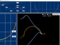
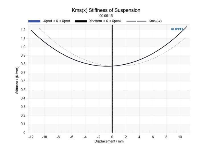
The test driver is a 6.25” woofer with carbon fiber cone, large diameter CCAW coil and spider with a woven lead wire. Datasheets show two curves from DA2 testing Bl(x) and Kms(x). These are shown in Figure 1 and Figure 2, respectively. The datasheet shows a linear excursion of ±12mm and maximum excursion of ±15mm.

For most of my tests I set these limits at 25% with a high temperature limit of 150°C. These are a more realistic approximation of what the driver will see in (aggressive) use. Note that I “ride” these values constantly during the test to prevent damage. The updated Bl(x) and Kms(x) curves depicted in Figure 3 and Figure 4 are tests accomplished with these limits. From these new curves you can clearly see that there is an asymmetry that needs to be evaluated. This can be done using the two new Bl and Kms symmetry range curves shown in Figure 5 and Figure 6.
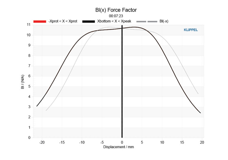
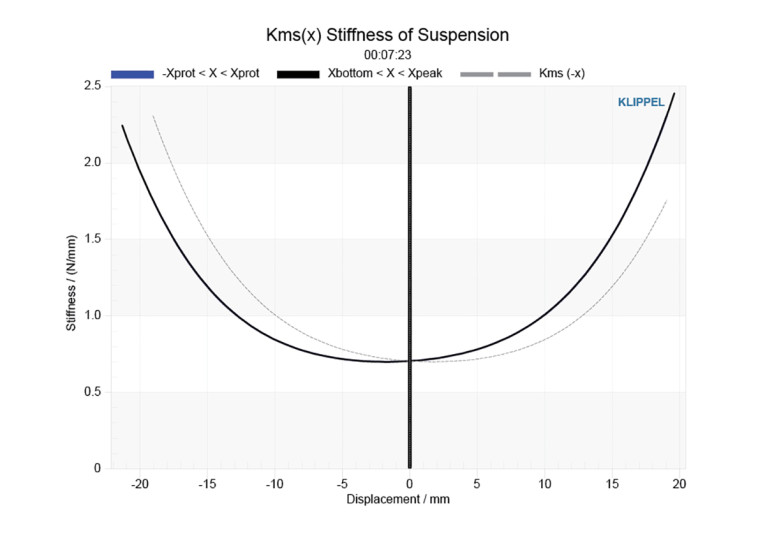
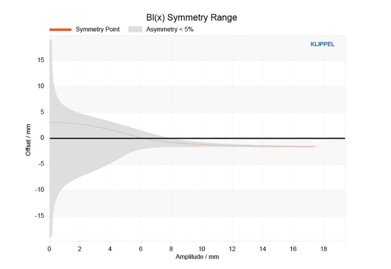
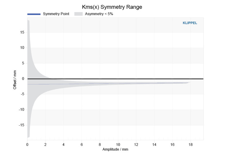
The Bl(x) symmetry curve shows some offset as the excursion passed 8mm. The range below this is essentially a window of error caused by the highly linear Bl(x) (nice motor design!). The lower Kms(x) symmetry range curve shows a clear bias in the down direction. Both curves show about 1.4mm of bias. Because both curves show this bias, experience suggest that there is a mechanical offset.
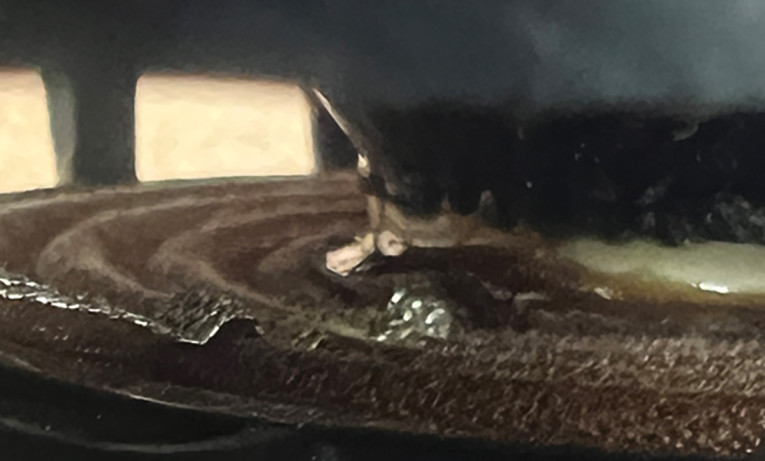
Physical examination of the moving parts show a dished-out spider (the lead out tinsel wire was stitched onto the spider). This can be caused by many factors, but typically it is the result of a mechanical stack-up error. In this case, cone assembly parts do not allow a passive ± = 0 rest position. My conclusion is that the cone neck is too long, the spider neck up design wasn’t calculated correctly, and so forth.
If the Bl(x) symmetry curve looked correct, it would have also been possible that the stitched lead wire was causing asymmetrical limits in the spider motion. This is always a concern when using this type of spider. This can also mean a mechanical weakness after long periods of high excursion. The lead wires tighten more in one direction than the other and the joint between coil and the lead wire can fracture and cause and open short (Photo 1).
For more information, visit the Redrock Acoustics website at www.redrockacoustics.com.
This article was originally published in Voice Coil, January 2024